Adobe Creative Cloud Design Tools All-in-One For Dummies (2013)
Book III
Illustrator CC
Chapter 5: Using the Pen Tool and Placing Images
In This Chapter
![]() Familiarizing yourself with the Pen tool
Familiarizing yourself with the Pen tool
![]() Creating paths, closed shapes, and curves
Creating paths, closed shapes, and curves
![]() Using the hidden Pen tools
Using the hidden Pen tools
![]() Tracing some artwork
Tracing some artwork
![]() Using the Image Trace feature
Using the Image Trace feature
![]() Placing images in Illustrator CC
Placing images in Illustrator CC
You’ve seen illustrations that you know are made from paths, but how do you make your own? In this chapter, we show you how to use the Pen tool to create paths and closed shapes.
 Using the Pen tool requires a little more coordination than using other Illustrator tools. Fortunately, Adobe Illustrator includes features to help make using the Pen tool a little easier. After you master the Pen tool, the possibilities for creating illustrations are unlimited. Read this chapter to build your skills using one of most popular tools in the creative industry: the Pen tool’s Bézier curve capabilities.
Pen Tool Fundamentals
![]() You can use the Pen tool to create all sorts of elements, such as straight lines, curves, and closed shapes, which you can then incorporate into illustrations:
You can use the Pen tool to create all sorts of elements, such as straight lines, curves, and closed shapes, which you can then incorporate into illustrations:
![]() Bézier curve: Originally developed by Pierre Bézier in the 1970s for CAD/CAM operations, the Bézier curve (shown in Figure 5-1) became the underpinnings of the entire Adobe PostScript drawing model. You can control the depth and size of a Bézier curve by using direction lines.
Bézier curve: Originally developed by Pierre Bézier in the 1970s for CAD/CAM operations, the Bézier curve (shown in Figure 5-1) became the underpinnings of the entire Adobe PostScript drawing model. You can control the depth and size of a Bézier curve by using direction lines.
Figure 5-1: Bézier curves are controlled by direction lines.
![]() Anchor point: You can use anchor points to control the shape of a path or an object. Anchor points are created automatically when using shape tools. You can manually create anchor points by clicking from point to point with the Pen tool.
Anchor point: You can use anchor points to control the shape of a path or an object. Anchor points are created automatically when using shape tools. You can manually create anchor points by clicking from point to point with the Pen tool.
![]() Direction line: These lines are essentially the handles you use on curved points to adjust the depth and angle of curved paths.
Direction line: These lines are essentially the handles you use on curved points to adjust the depth and angle of curved paths.
![]() Closed shape: When a path is created, it becomes a closed shape when the start point joins the endpoint.
Closed shape: When a path is created, it becomes a closed shape when the start point joins the endpoint.
![]() Simple path: A path consists of one or more straight or curved segments. Anchor points mark the endpoints of the path segments.
Simple path: A path consists of one or more straight or curved segments. Anchor points mark the endpoints of the path segments.
In the next section, we show you how to control the anchor points.
Creating a straight line
A basic function of the Pen tool is to create a simple path. You can create a simple, straight line with the Pen tool by following these steps:
1. Press D or click the small black-and-white color swatches at the bottom of the Tools panel.
You revert to the default colors of a black stroke and a white fill. With black as a stroke, you can see your path clearly.
 The trick of pressing D to change the foreground and background colors to the default of black and white also works in Photoshop and InDesign.
2. Click the Fill swatch, at the bottom of the Tools panel, to ensure that the Fill swatch is in front of the Stroke swatch, and then press the forward slash (/) key to change the fill to None.
3. Open a new blank page and select the Pen tool.
Notice that when you move the mouse over the artboard, the Pen cursor appears with an X beside it, indicating that you’re creating the first anchor point of a path.
4. Click the artboard to create the first anchor point of a line.
The X disappears.
 Avoid dragging the mouse or you’ll end up creating a curve rather than a straight segment.
5. Click anywhere else on the document to create the ending anchor point of the line.
Illustrator creates a path between the two anchor points. Essentially, the path looks like a line segment with an anchor point at each end. (See Figure 5-2.)
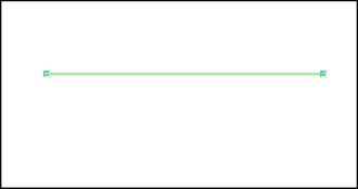
Figure 5-2: A path connected by two anchor points.
To make a correction to a line you created with the Pen tool (as described in the preceding step list), follow these steps:
1. Choose Select⇒Deselect to make sure that no objects are selected.
2. Select the Direct Selection tool from the Tools panel.
Notice the helpful feature that enlarges the anchor point when you pass over it with the Direct Selection tool.
3. Click an anchor to select one point on the line.
Notice that the selected anchor point is solid and the other is hollow. Solid indicates that the anchor point you clicked is active, whereas hollow is inactive.
4. Click and drag the anchor point with the Direct Selection tool.
The selected anchor point moves, changing the direction of the path while not affecting the other anchor point.
Use the Direct Selection tool (press A to use the keyboard shortcut to select the Direct Selection tool) to make corrections to paths.
Make sure that only the anchor point you want to change is active. If the entire path is selected, all anchor points are solid. If only one anchor point is selected, all but that one point will be hollow.
Creating a constrained straight line
In this section, we show you how to create a real straight line — one that’s on multiples of a 45-degree angle. Illustrator makes it easy; just follow these steps:
1. Select the Pen tool and click the artboard anywhere to place an anchor point.
2. Hold down the Shift key and click another location to place the ending anchor point.
Notice that when you’re holding down the Shift key, the line snaps to a multiple of 45 degrees.
Release the mouse button before you release the Shift key or else the line pops out of alignment.
Creating a curve
In this section, you see how to use the Bézier path to create a curved segment. We don’t guarantee that you’ll love this process — not at first, anyway. But after you know how to use a Bézier path, you’ll likely find it useful. To create a Bézier path, follow these steps:
1. Starting with a blank artboard, select the Pen tool and click the artboard anywhere to place the first anchor point.
2. Click someplace else to place the ending anchor point — don’t let go of the mouse button — and then drag the cursor until a direction line appears.
If you look closely, you see that anchor points are square and that direction lines have circles at the end, as shown in Figure 5-3.
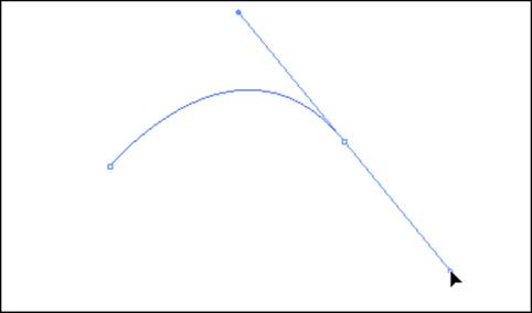
Figure 5-3: Click and drag with the Pen tool to create a curved path.
3. Drag the direction line closer to the anchor point to flatten the curve; drag farther away from the anchor point to increase the curve, as shown in Figure 5-4.
4. When you’re happy with the curve, release the mouse button.
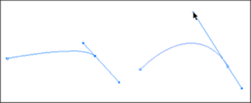
Figure 5-4: Adding curve to the curve.
You’ve created an open path, or a path that doesn’t form a closed shape. We show you in the next section how to reconnect to the starting point of the path to make a closed shape.
To alter a curved segment after you create it, follow these steps:
1. Choose Select⇒Deselect to ensure that no objects are selected.
2. Choose the Direct Selection tool and click the last anchor point created.
If the direction lines aren’t already visible, they appear.
If you have difficulty selecting the anchor point, drag a marquee around it with the Direct Selection tool.
3. Click precisely at the end of one of the direction lines; drag the direction line to change the curve.
Reconnecting to an existing path
Creating one segment is fine if you want just a line or an arch. But if you want to create a shape, you need to add more anchor points to the original segment. If you want to fill your shape with a color or a gradient, you need to close it, which means that you need to eventually return to the starting anchor point.
To add segments to your path and create a closed shape, follow these steps:
1. Create a segment (straight or curved).
We show you how in the preceding sections of this chapter.
You can continue from this point, clicking and adding anchor points until you eventually close the shape. For this example, you deselect the path so that you can discover how to continue adding to paths that have already been created. Knowing how to edit existing paths is extremely helpful when you need to make adjustments to artwork.
2. With the Pen tool selected, move the cursor over an end anchor point on the deselected path.
3. Click when you see the Pen icon with a forward slash to connect your next segment.
The forward slash indicates that you’re connecting to this path.
4. Click someplace else to create the next anchor point in the path; drag the mouse if you want to create a curved segment.
5. Click to place additional anchor points, dragging as needed to curve those segments.
Remember that you want to close this shape, so place the anchor points so that you can eventually come back to the first anchor point.
The shape shown in Figure 5-5 is a result of adding several linked anchor points.
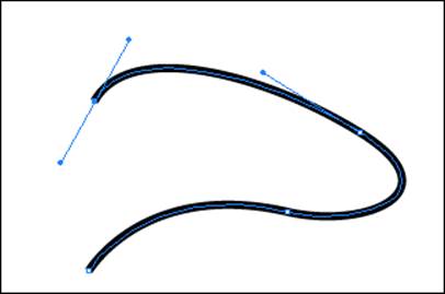
Figure 5-5: Adding anchor points to create a shape.
6. When you return to the first anchor point, move the cursor over it and click when the close icon (a small, hollow circle) appears, as shown in Figure 5-6.
The shape now has no endpoints.
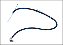
Figure 5-6: Click when the close path icon appears.
Controlling curves
After you feel comfortable creating curves and paths, take control of those curves so that you can create them with a greater degree of precision. The following steps walk you through the manual method for changing the direction of anchor points and reveal a helpful keyboard shortcut to make controlling paths a little more fluid. At the end of this section, we introduce new tools that you may also want to take advantage of to help you get control of the Pen tool.
To control a curve, follow these steps:
1. Create a new document and then choose View⇒Show Grid to show a series of horizontal and vertical rules that act as guides.
If it helps, use the Zoom tool to zoom in to the document.
2. With the Pen tool, click an intersection of any of these lines in the middle area of the page to place the initial anchor point and drag upward.
Let go but don’t click when the direction line has extended to the horizontal grid line above it, as shown in Figure 5-7a.
3. Click to place the second anchor point on the intersection of the grid directly to the right of your initial point; drag the direction line to the grid line directly below it, as shown in Figure 5-7b.
If you have difficulty keeping the direction line straight, hold down the Shift key to constrain it.
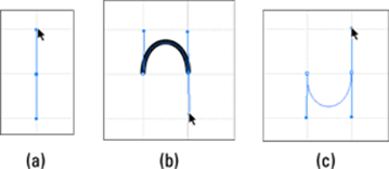
Figure 5-7: Creating a controlled Bézier curve.
4. Choose Select⇒Deselect to deselect your curve.
Congratulations! You’ve created a controlled curve. In these steps, you created an arch that’s going up, so you first clicked and dragged up. Likewise, to create a downward arch, you must click and drag down. Using the grid, try to create a downward arch like the one shown in Figure 5-7c.
Creating a corner point
To change the direction of a path from being a curve to a corner, you have to create a corner point, shown on the right in Figure 5-8. A corner point has no direction lines and allows for a sharp directional change in a path.
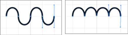
Figure 5-8: Smooth versus corner points.
You can switch from the Pen tool to the Convert Anchor Point tool to change a smooth anchor point into a corner point, but that process is time-consuming. An easier way is to press the Alt (Windows) or Option (Mac) key — the Pen tool temporarily changes into the Convert Anchor Point tool — while clicking the anchor point.
To change a smooth anchor point into a corner point by using the shortcut method, follow these steps:
1. Create an upward arch.
We show you how in the preceding section, Controlling curves. (Refer to Figure 5-7b.)
2. Hold down the Alt (Windows) or Option (Mac) key and position the cursor over the last anchor point (the last point that you created with the Pen tool).
![]() 3. When the cursor changes to a caret (that’s the Convert Anchor Point tool), click and drag until the direction line is up to the grid line above, as shown on the left in Figure 5-9.
3. When the cursor changes to a caret (that’s the Convert Anchor Point tool), click and drag until the direction line is up to the grid line above, as shown on the left in Figure 5-9.
4. Release the Alt (Windows) or Option (Mac) key and the mouse button, move the cursor to the grid line to the right, and click and drag down.
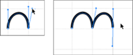
Figure 5-9: Converting from smooth to corner.
The Hidden Pen Tools
Hold down the Pen tool icon in the Tools panel to access additional tools: the Add Anchor Point, Delete Anchor Point, and Convert Anchor Point tools, shown in Table 5-1. In the preceding section, we show you how to create a corner point by using the shortcut method, by pressing the Alt (Windows) or Option (Mac) key to access the Convert Anchor Point tool. You may feel more comfortable switching to that tool when you need to convert a point, but switching tools can be more time-consuming.
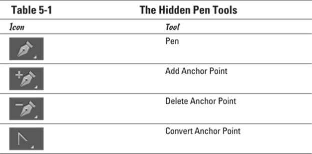
Even though you can use a hidden tool to delete and add anchor points, Illustrator automatically does this as a default when you’re using the Pen tool. When you move the cursor over an anchor point by using the Pen tool, a minus icon appears. To delete that anchor point, simply click. Likewise, when you move the cursor over a part of the path that doesn’t contain anchor points, a plus icon appears. Simply click to add an anchor point.
If you prefer to use the tools dedicated to adding and deleting anchor points, choose Edit⇒Preferences⇒General (Windows) or Illustrator⇒Preferences⇒General (Mac); in the Preferences dialog box that appears, select the Disable Auto Add/Delete check box. Then, when you want to add or delete an anchor point, select the appropriate tool and click the path.
Adding tools to help make paths
Some Pen tool modifiers are available in the Control panel in Illustrator CC. You can take advantage of them for many Pen tool uses, but using keyboard shortcuts to switch the Pen tool to its various options is probably still faster. If you’re resistant to contorting your fingers while trying to create a path, you should appreciate these tools.
![]() To see the Control panel tools, select the Pen tool and start creating a path. Notice that the Control panel has a series of buttons available, shown in Figure 5-10.
To see the Control panel tools, select the Pen tool and start creating a path. Notice that the Control panel has a series of buttons available, shown in Figure 5-10.
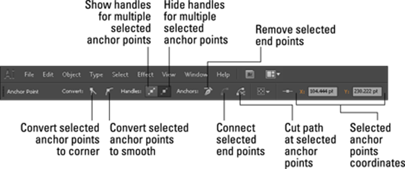
Figure 5-10: Control panel tools for easy editing.
Using the Eraser tool
If you haven’t discovered the Eraser tool, you will wonder how you got along without it! Using the Eraser tool, you can quickly remove areas of artwork as easily as you erase pixels in Photoshop by stroking with your mouse over any shape or set of shapes.
New paths are automatically created along the edges of the erasure, even preserving its smoothness, as shown in Figure 5-11.
Figure 5-11: The Eraser tool deletes sections of a path.
By double-clicking the Eraser tool, you can define the diameter, angle, and roundness of your eraser. (See Figure 5-12.) If you’re using a drawing tablet, you can even set Wacom tablet interaction parameters, such as Pressure and Tilt.
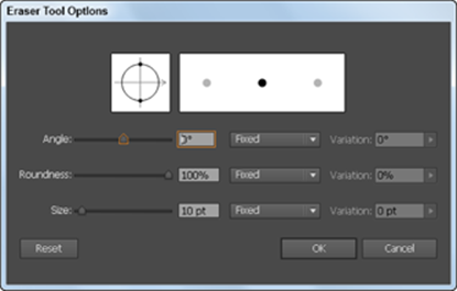
Figure 5-12: Double-click the Eraser tool to set various tool options.
If you want to erase more than a single selected object, use Isolation mode to segregate grouped objects for editing. Remember that in order to enter this mode, you simply double-click a group of items. You can then use the eraser on all objects in that group at one time without disturbing the rest of your design.
Tracing Artwork
You can use a template layer to trace an image manually. A template layer is a locked, dimmed layer you can use to draw over placed images with the Pen tool, much like you would do with a piece of onion skin paper over the top of an image.
Creating a template layer
Follow these steps to create a template layer:
1. Take a scanned image or logo and save it in a format that Illustrator can import from your image-editing program, such as Photoshop.
Typically, you save the image as an .eps, a .tif, or a native .psd (Photoshop) file.
2. Choose File⇒Place to open the Place dialog box.
3. In the Place dialog box, locate the saved image; then select the Template check box and click Place.
Note that the Template check box is located at the bottom of the dialog box.
Selecting the Template check box tells Illustrator to lock down the scanned image on a layer. Essentially, you can’t reposition or edit your image.
After you click Place, a template layer is automatically created for you, and another layer is waiting for you to create your path. The newly created top layer resembles a piece of tracing paper that has been placed on top of the scanned image.
4. Re-create the image by tracing over it with the Pen tool.
5. When you’re done, turn off the visibility of the placed image by clicking the Visibility icon to the left of the template layer.
You now have a path you can use in place of the image, which is useful if you’re creating an illustration of an image or are digitally re-creating a logo.
For more about layers, check out Chapter 8 of this minibook.
Keep practicing to become more comfortable with clicking and dragging, flowing with the direction line pointing the way you want the path to be created; everything will fall into place.
Using Image Trace
With the Image Trace feature, you can take raster (bitmap) artwork and automatically trace it to convert it into vector artwork. This means that you can take scans of sketches, illustrations, and even photographs, and convert them into vector artwork that can be edited in Illustrator. The Image Trace feature is not totally new — in previous versions it was known as Live Trace — but with CC it has been greatly improved. Additional options have been added, and you can easily access those options and “test” your trace using the new Image Trace panel. Follow these steps to try out this improved feature:
1. Choose File⇒Place and place a scan or raster illustration that you want to convert to vector paths.
Immediately after placing, you see that the Control panel now has additional buttons available, as shown in Figure 5-13.
Even though you can click Image Trace immediately, you may want to consider selecting Window⇒Image Trace to access the Image Trace panel, which offers you more options and the opportunity to test your selections in advance.
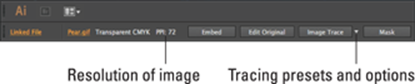
Figure 5-13: Image Trace Control panel features.
2. Click the Preset drop-down menu to select a preset most similar to the artwork you want to convert.
Many of the presets are defined according to the type of artwork that you are tracing — such as a sketch, technical drawing, or photograph. (See Figure 5-14.) The 3 Colors, 6 Colors, and 16 Colors options are useful when converting a photograph to a vector image.
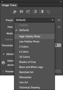
Figure 5-14: Select a preset that best fits your placed image.
3. Expand the Advanced section and note the additional path options available there:
• Paths determines how accurate a representation of the original art the path trace will be. The higher the percentage, the more accurate the tracing. (See Figure 5-15.) Be careful with this feature — if you set the percentage too high, you can end up with more anchor points than necessary. By default, this setting is at 50%, which should work for most of your artwork.
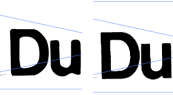
Figure 5-15: The image on the left has a low path tolerance of 0%. The image on the right has a high path tolerance of 100%.
• Corner determines how the Image Trace traces corners. A lower percentage produces a more rounded corner; a higher amount a sharper corner. (See Figure 5-16.) Again, the default setting (75%) works for most cases.
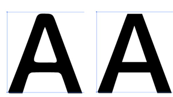
Figure 5-16: On the left, a traced image with the corner setting at 0%. On the right, a traced image with a corner setting of 100%.
• Noise determines the minimum details size Image Trace can reproduce. The default of 100 pixels tends to work well. This provides you an area that will be recognized by the Image Trace feature of about 10 x 10 pixels. You might have to play with this setting a bit to see what works best for your image.
Changing the View
Can’t see the results of your trace? Keep in mind that you can change the view. Just select the traced image and click the View drop-down menu in the Control panel. Using this you can turn off and on the view for the original image as well as the tracing results.
Image Trace is a memory-intensive feature, and your computer may take a little more time than normal to preview each preset.
See Chapter 9 of this minibook for more information on painting fills and strokes.
Other Details You Should Know about Placing Images
In the preceding section, you discover how to place an image as a template. But what if you want to place an image to be used in an illustration file? Simply choose File⇒Place.
Click an image once to see its Link check box. If you keep the check box selected, the image is linked to the original file, which is helpful if you plan to reference the file several times in the illustration (it saves file space) or edit the original and have it update the placed image in Illustrator. This option is usually selected by people in the prepress industry who want to have access to the original image file. Just remember to send the image with the Illustrator file if it’s to be printed or used someplace other than on your computer.
If you are worried about keeping all your placed files associated with your Illustrator file, you can now use File⇒Package in Illustrator CC. This feature gives you the option to create a folder that contains your linked files, fonts, and a report about your file, as you see in Figure 5-17.
If you deselect the Link check box, the image is embedded into the Illustrator file. This option builds the image data into the Illustrator file. With an embedded image you won’t need to remember where the original file is stored, but it does make for a larger Illustrator file. Now that you have the ability to choose Unembed from the Links panel menu, you can retrieve the image data and save it for future editing if you need to. In certain instances, such as when you want an image to become a symbol (see Chapter 11 of this minibook), the image will have to be embedded, but most functions work with both linked and unlinked files.
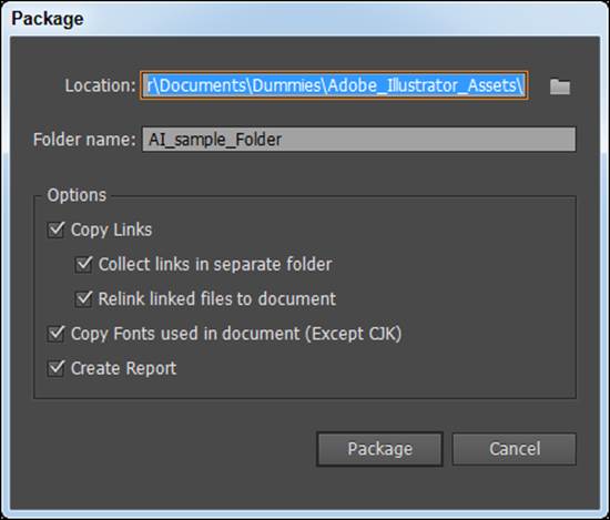
Figure 5-17: Collect images fonts and create a report using the new Package feature.
Using Photoshop Layer Comps
The Layer Comps feature in Photoshop lets you set the visibility, appearance, and position of layers. You can take advantage of this useful organizational tool in other Adobe products. Read more about Photoshop in Book IV.
You can place in Illustrator a .psd (Photoshop) image that has saved Layer Comps and choose which layer comp set you want visible.
All materials on the site are licensed Creative Commons Attribution-Sharealike 3.0 Unported CC BY-SA 3.0 & GNU Free Documentation License (GFDL)
If you are the copyright holder of any material contained on our site and intend to remove it, please contact our site administrator for approval.
© 2016-2026 All site design rights belong to S.Y.A.