iOS Game Development Cookbook (2014)
Chapter 8. 3D Graphics
Using 3D graphics is the most popular approach for games these days. However, 3D is complicated. It’s so complicated, in fact, that we’re going to dedicate three whole chapters to it. The first chapter (this one) covers introductory 3D—setup, basic drawing, and understanding how 3D works overall. The next two chapters cover more intermediate and advanced topics in 3D rendering on the iPhone and iPad.
When you work in 3D, you use a library called OpenGL ES. OpenGL ES is the “embedded” version of OpenGL, the industry-standard library for computer graphics. OpenGL is everywhere—you’ll find it in desktop computers, in games consoles, in industrial hardware, and in mobile computers like iOS devices.
Because OpenGL is designed to be cross-platform, it doesn’t have the same nice API as you might be used to from working with other tools on iOS. Apple’s put quite a bit of effort into making things as easy as possible for developers, introducing a framework called GLKit that helps with the setup and integration of OpenGL in your game. However, you’ll still need to get used to how OpenGL works.
Because it’s not really possible to talk about 3D graphics features in isolation, this chapter is actually designed to be read in sequence. Whereas in other chapters you can basically jump straight to any recipe, we recommend that you start this one at the beginning and read through. As a precursor to the recipes, we’ll begin with an introduction to 3D math.
Working with 3D Math
In addition to providing lots of useful support classes and functions for working with 3D graphics, GLKit also includes a number of types and functions that are helpful for working with 3D math.
The two most common kinds of mathematical constructs that you’ll see when doing 3D math are vectors and matrices. We talked about two-dimensional vectors in Vectors; the 3D equivalent is a three-dimensional vector.
3D Vectors and GLKit
A 3D vector has three components. By convention, these are referred to as x, y, and z. In GLKit, a 2D vector is represented by the GLKVector2 structure, and 3D vectors are represented by GLKVector3 objects:
GLKVector2 myVector2D;
myVector2D.x = 1;
myVector2D.y = 2;
GLKVector3 myVector3D;
myVector2D.x = 1;
myVector2D.y = 2;
myVector2D.z = 4;
GLKit provides a number of useful functions for working with vectors:
GLKVector3Add and GLKVector2Add
Add two vectors together.
GLKVector3Subtract and GLKVector2Subtract
Subtract one vector from another.
GLKVector3Distance and GLKVector2Distance
Get the distance from one vector to another.
GLKVector3Length and GLKVector2Length
Get the length (or magnitude) of a vector.
GLKVector3Normalize and GLKVector2Normalize
Get the normalized version of a vector (i.e., a vector with the same direction as the original but with a length of 1).
GLKVector3DotProduct and GLKVector2DotProduct
Get the dot product between two vectors.
For more information on what these functions involve, see Vectors.
Matrices
A matrix is a grid of numbers (see Figure 8-1).
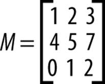
Figure 8-1. A matrix
On their own, matrices are just a way to store numbers. However, matrices are especially useful when they’re combined with vectors. This is because you can multiply a matrix with a vector, which results in a changed version of the original vector.
Additionally, if you multiply two matrices together, the result is a matrix that, if you multiply it with a vector, has the same result as if you had multiplied the vector with each matrix individually. This means that a single matrix can be used to represent a combination of operations.
Additionally, there’s a single matrix that, if multiplied with a vector, returns a vector with no changes (i.e., it returns the original vector). This is referred to as the identity matrix, and it’s a good starting point for building a matrix: you start with the identity matrix and then translate it, rotate it, and so on.
The three most useful things a matrix can do with a vector are:
Translation
Moving the vector
Rotation
Rotating the vector in 3D space
Scaling
Increasing or decreasing the distance of the vector from the origin
Another common kind of matrix, called a perspective projection transform matrix, does the work of making objects get smaller as they move away from the origin point. You can multiply a vector with a perspective projection transform matrix, just like any other transform.
Conversely, if you use an orthographic projection transform matrix, objects remain the same size no matter how far away they get. In both of these cases, you define the height and width of the view area, and objects outside of the view area aren’t visible.
In GLKit, the GLKMatrix4 structure represents a 4-by-4 matrix, which you use with vectors to apply transforms. GLKMatrix4Identity is the identity matrix.
You can create matrices that represent specific transformations by using the GLKMatrix4MakeTranslation, GLKMatrix4MakeRotation, and GLKMatrix4MakeScale functions:
// Make a matrix that represents a translation of 1 unit on the y-axis
GLKMatrix4 translationMatrix = GLKMatrix4MakeTranslation(0, 1, 0)
// Make a matrix that represents a rotation of π radians around the x-axis
GLKMatrix4 rotationMatrix = GLKMatrix4MakeRotation(M_PI, 1, 0, 0);
// Make a matrix that represents a scaling of 0.9 on the x-axis,
// 1.2 on the y-axis, and 1 on the z-axis
GLKMatrix4 scaleMatrix = GLKMatrix4MakeScale(0.9, 1.2, 1);
Once you have a matrix, you can create additional matrices, and combine them together using GLKMatrixMultiply:
GLKMatrix4 translationMatrix = GLKMatrix4MakeTranslation(0, 1, 0)
GLKMatrix4 rotationMatrix = GLKMatrix4MakeRotation(M_PI, M_PI_2, 0);
GLKMatrix4 translateAndRotateMatrix = GLKMatrix4Multiply(translationMatrix,
rotationMatrix);
Once you’re done constructing your matrices, you give them to GLKit when it needs a model view matrix. Model view matrices are discussed in Drawing a Cube.
Finally, you can create projection matrices using the GLKMatrix4MakePerspective and GLKMatrix4MakeOrtho functions.
When you create a perspective projection, you need to provide four pieces of information:
Field of view
How “wide” the viewable region should be, measured in radians. The field of view is the angle from the leftmost viewable point to the rightmost viewable point.
Aspect ratio
The width of the viewable area, as a ratio to its height. For example, if you want the viewable region to be twice as wide as the height, the aspect ratio is 2; if you want the viewable region to be one-third the height, the aspect ratio is 0.333.
Near clipping plane
The minimum distance from the camera at which objects are allowed to be.
Far clipping plane
The maximum distance from the camera at which objects are allowed to be.
NOTE
Humans have a field of view of almost 180° (i.e., π radians), but using this setting can cause problems in a game because the screen takes up a much smaller section of the player’s field of view. Play around with 90° to 70° (i.e., π/2, or 1.57 radians to 1.22 radians).
Creating an orthographic projection requires different information. You need to provide the following:
§ The left coordinate of the viewable region, relative to the center (i.e., the coordinate (0,0) is the center of the viewable region; if you want objects 5 units to the left of the camera to be viewable, you set this to –5)
§ The right coordinate of the viewable region
§ The bottom coordinate
§ The top coordinate
§ The near coordinate (i.e., the minimum distance that objects can be from the camera)
§ The far coordinate (the maximum distance that objects can be from the camera)
Here’s how you create perspective and orthographic matrices:
// Make a perspective projection with a π/2 (i.e., 90°) field of view,
// a 1.5:1 aspect ratio (the viewable area is 1.5x as wide as it is high),
// a near clipping plane 0.1 units away, and a far clipping plane 200
// units away
GLKMatrix4 perspectiveMatrix = GLKMatrix4MakePerspective(M_PI_2, 1.5, 0.1, 1.0);
// Make an orthographic projection with left coordinate -5,
// right coordinate 5, bottom coordinate -5, top coordinate 5,
// near coordinate 0.1, and far coordinate 200
GLKMatrix4 orthographicMatrix = GLKMatrix4MakeOrtho(-5, 5, -5, 5, 0.1, 100);
With this math primer in mind, it’s on to the recipes!
Creating a GLKit Context
Problem
You want to create an application that draws using OpenGL.
Solution
Note that while Xcode includes a template that sets up a lot of this for you, in this exercise we’re going to go through each part of it step by step, so you can understand it better:
1. Create a new single-view application.
2. Import GLKit.framework and OpenGLES.framework.
3. Open ViewController.xib.
4. Select the view, open the Identity inspector, and set the view’s class to GLKView.
5. Open ViewController.h, import GLKit/GLKit.h, and change ViewController’s parent class from UIViewController to GLKViewController.
6. Add the following code to viewDidLoad:
7. GLKView* view = (GLKView*)self.view;
view.context = [[EAGLContext alloc] initWithAPI:kEAGLRenderingAPIOpenGLES2];
8. Then add the following method:
9. - (void)glkView:(GLKView *)view drawInRect:(CGRect)rect {
10. glClearColor(0.0, 0.5, 0.0, 1.0);
11. glClear(GL_COLOR_BUFFER_BIT);
}
Discussion
When you create a GLKit context, you’re creating the space in which all of your 3D graphics will be drawn. GLKit contexts are contained inside GLKView objects, which are just UIView objects that know how to draw OpenGL content.
When the context gets created, you need to specify which version of the OpenGL ES API you want to use. There are three different versions that you can use:
§ OpenGL ES 1.0, which supports very simple, fixed-function rendering
§ OpenGL ES 2.0, which adds support for pixel shaders (small programs that let you customize a great deal of the rendering process)
§ OpenGL ES 3.0, which adds a number of low-level features that improve rendering speed and flexibility
NOTE
The changes from OpenGL ES 1.0 to 2.0 were much more significant than the changes from 2.0 to 3.0. The new stuff in 3.0 isn’t as relevant to people starting out using OpenGL ES, so what we’re covering in this book is largely content that was added in 2.0.
OpenGL works by continuously redrawing the entire scene every time a frame needs to be shown. Every time this happens, your GLKView calls the glkView:drawInRect: method. In this example, the only thing that happens is that the content of the view is cleared:
glClearColor(0.0, 0.5, 0.0, 1.0);
glClear(GL_COLOR_BUFFER_BIT);
The first line of the code calls glClearColor, which effectively tells OpenGL that the clear color should be set to the RGBA value (0.0, 0.5, 0.0, 1.0)—that is, fully opaque, dark green.
The next line instructs OpenGL to actually clear the color buffer—that is, it fills the entire screen with the clear color that was set on the previous line (see Figure 8-2).
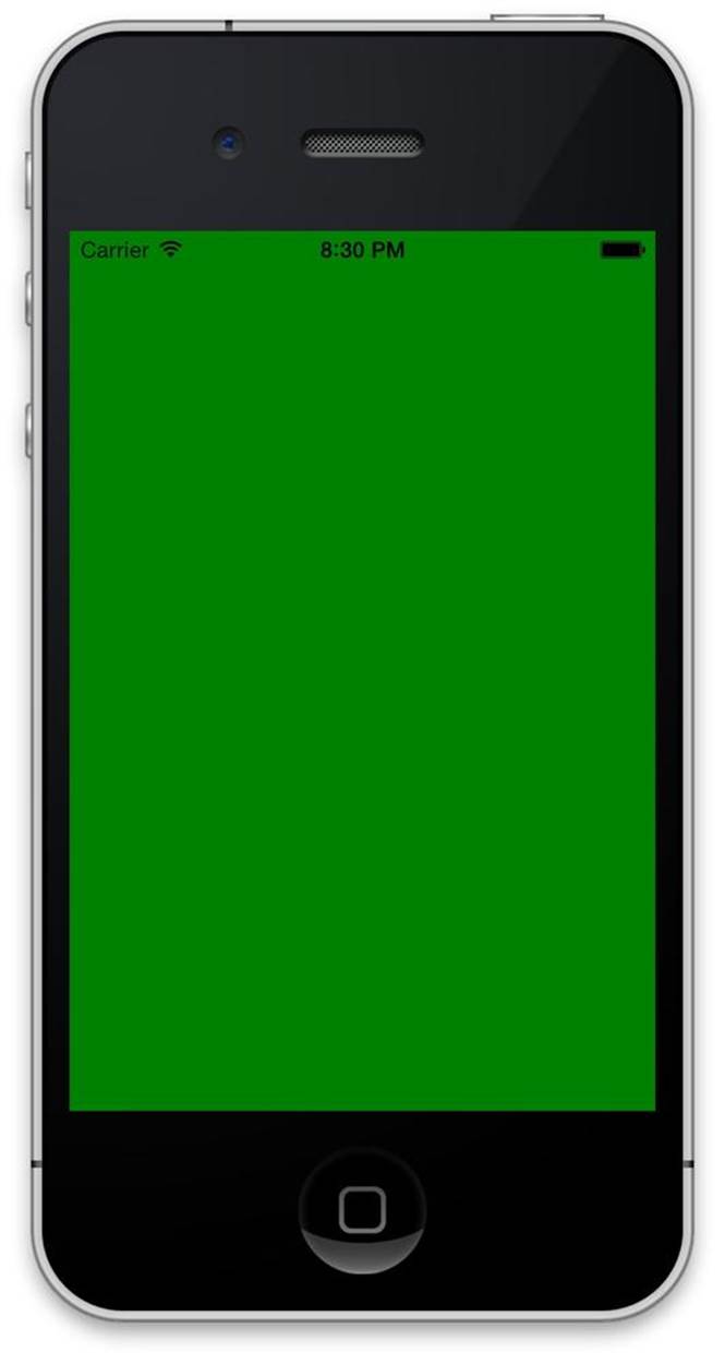
Figure 8-2. The final result of this recipe: a screen filled with solid color
Drawing a Square Using OpenGL
Problem
You want to draw a square on the screen using OpenGL.
Solution
Make ViewController.m contain this code:
#import "ViewController.h"
typedef struct {
GLKVector3 position;
} Vertex;
const Vertex SquareVertices[] = {
{-1, -1 , 0}, // bottom left
{1, -1 , 0}, // bottom right
{1, 1 , 0}, // top right
{-1, 1 , 0}, // top left
};
const GLubyte SquareTriangles[] = {
0, 1, 2, // BL->BR->TR
2, 3, 0 // TR->TL->BL
};
@interface ViewController () {
GLuint _vertexBuffer; // contains the collection of vertices used to
// describe the position of each corner
GLuint _indexBuffer; // indicates which vertices should be used in each
// triangle used to make up the square
GLKBaseEffect* _squareEffect; // describes how the square is going to be
// rendered
}
@end
@implementation ViewController
- (void)viewDidLoad
{
[super viewDidLoad];
// Do any additional setup after loading the view, typically from a nib
GLKView* view = (GLKView*)self.view;
view.context = [[EAGLContext alloc] initWithAPI:kEAGLRenderingAPIOpenGLES2];
[EAGLContext setCurrentContext:view.context];
// Create the vertex array buffer, in which OpenGL will store the vertices
// Tell OpenGL to give us a buffer
glGenBuffers(1, &_vertexBuffer);
// Make this buffer be the active array buffer
glBindBuffer(GL_ARRAY_BUFFER, _vertexBuffer);
// Put this data into the active array buffer. It's as big as the
// 'SquareVertices' array, so we can use the data from that array;
// also, this data isn't going to change.
glBufferData(GL_ARRAY_BUFFER, sizeof(SquareVertices), SquareVertices,
GL_STATIC_DRAW);
// Now do the same thing for the index buffer, which indicates which
// vertices to use when drawing the triangles
glGenBuffers(1, &_indexBuffer);
glBindBuffer(GL_ELEMENT_ARRAY_BUFFER, _indexBuffer);
glBufferData(GL_ELEMENT_ARRAY_BUFFER, sizeof(SquareTriangles),
SquareTriangles, GL_STATIC_DRAW);
// Prepare the GL effect, which tells OpenGL how to draw our triangle
_squareEffect = [[GLKBaseEffect alloc] init];
// First, we set up the projection matrix
float aspectRatio = self.view.bounds.size.width /
self.view.bounds.size.height;
float fieldOfViewDegrees = 60.0;
GLKMatrix4 projectionMatrix = GLKMatrix4MakePerspective(
GLKMathDegreesToRadians(fieldOfViewDegrees),
aspectRatio, 0.1, 10.0);
_squareEffect.transform.projectionMatrix = projectionMatrix;
// Next, we describe how the square should be positioned (6 units away
// from the camera)
GLKMatrix4 modelViewMatrix = GLKMatrix4MakeTranslation(0.0f, 0.0f, -6.0f);
_squareEffect.transform.modelviewMatrix = modelViewMatrix;
// Tell the effect that it should color everything with a single color
// (in this case, red)
_squareEffect.useConstantColor = YES;
_squareEffect.constantColor = GLKVector4Make(1.0, 0.0, 0.0, 1.0);
}
- (void)glkView:(GLKView *)view drawInRect:(CGRect)rect {
// Erase the view by filling it with black
glClearColor(0.0, 0.0, 0.0, 1.0);
glClear(GL_COLOR_BUFFER_BIT);
// Tell the effect that it should prepare OpenGL to draw using the
// settings we've configured it with
[_squareEffect prepareToDraw];
// OpenGL already knows that the vertex array (GL_ARRAY_BUFFER) contains
// vertex data. We now tell it how to find useful info in that array.
// Tell OpenGL how the data is laid out for the position of each
// vertex in the vertex array
glEnableVertexAttribArray(GLKVertexAttribPosition);
glVertexAttribPointer(GLKVertexAttribPosition, 3, GL_FLOAT, GL_FALSE, 0, 0);
// Now that OpenGL knows where to find vertex positions, it can draw them
int numberOfVertices = sizeof(SquareTriangles)/sizeof(SquareTriangles[0]);
glDrawElements(GL_TRIANGLES, numberOfVertices, GL_UNSIGNED_BYTE, 0);
}
- (void)didReceiveMemoryWarning
{
[super didReceiveMemoryWarning];
// Dispose of any resources that can be re-created
}
@end
Discussion
Drawing triangles in OpenGL is easier than drawing squares or more complex polygons, because triangles are always coplanar—that is, all of the points in the shape are on the same plane.
So, to draw a square, what we do is draw two triangles that share an edge, as illustrated in Figure 8-3.
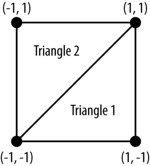
Figure 8-3. The vertices that define the triangles
This means that we need to tell OpenGL about two different things:
§ Where each of these vertices are
§ Which of these vertices are used in each triangle
To tell OpenGL about where the vertices are, we start by defining a structure for vertices and making an array. This will later be uploaded to OpenGL, so that it can be used:
typedef struct {
GLKVector3 position;
} Vertex;
const Vertex SquareVertices[] = {
{-1, -1 , 0}, // vertex 0: bottom left
{1, -1 , 0}, // vertex 1: bottom right
{1, 1 , 0}, // vertex 2: top right
{-1, 1 , 0}, // vertex 3: top left
};
The positions used in each vertex are defined in arbitrary “units.” These units can be anything you like: inches, centimeters, or whatever.
Once the vertices have been laid out, we need to define which triangles use which vertices. In OpenGL, we do this by numbering each vertex, and then describing triangles by giving OpenGL three numbers at a time:
const GLubyte SquareTriangles[] = {
0, 1, 2, // BL->BR->TR
2, 3, 0 // TR->TL->BL
};
In this case, the first triangle uses vertices 0, 1, and 2, and the second triangle uses vertices 2, 3, and 0. Note that both triangles use vertices 0 and 2. This means that they share an edge, which means that there won’t be any gap between the two triangles.
This data needs to be passed to OpenGL before it can be used. Both the SquareVertices and SquareTriangles arrays need to be stored in a buffer, which is OpenGL’s term for a chunk of information that it can use for rendering.
When you create a buffer, OpenGL gives you a number, which is the buffer’s name. (A name is still a number, not text—it’s just a weird OpenGL terminology thing.) When you want to work with a buffer, you use that buffer’s name. In this code, we store the names as instance variables:
@interface ViewController () {
GLuint _vertexBuffer; // contains the collection of vertices used to
// describe the position of each corner
GLuint _indexBuffer; // indicates which vertices should be used in each
// triangle used to make up the square
GLKBaseEffect* _squareEffect; // describes how the square is going to be
// rendered
}
@end
That last instance variable is a GLKBaseEffect, which is used to control the position of the square on the screen, as well as its color. We’ll come back to this in a few moments.
The first part of the actual code that gets executed is in viewDidLoad:. First, we set up the GLKView with an OpenGL context. Because we’re about to start issuing OpenGL commands, we also make that context the current context (if you don’t do this, none of your OpenGL commands will do anything):
GLKView* view = (GLKView*)self.view;
view.context = [[EAGLContext alloc] initWithAPI:kEAGLRenderingAPIOpenGLES2];
[EAGLContext setCurrentContext:view.context];
Next, we create the buffers, starting with the vertex buffer. It’s also bound to GL_ARRAY_BUFFER, which instructs OpenGL that whenever we’re talking about “the GL_ARRAY_BUFFER,” we mean _vertexBuffer. If you’re making a game where you have more than one array buffer (which is common), you call glBindBuffer every time you want to start working with a different array buffer:
glGenBuffers(1, &_vertexBuffer);
glBindBuffer(GL_ARRAY_BUFFER, _vertexBuffer);
The vertex buffer is then filled with the vertex information:
glBufferData(GL_ARRAY_BUFFER, sizeof(SquareVertices),
SquareVertices, GL_STATIC_DRAW);
The call to glBufferData basically says this: “Hey, OpenGL, I want you to put data into the currently bound GL_ARRAY_BUFFER. The size of the data is however big the SquareVertices array is, and the data should come from the SquareVertices array. Also, this data is unlikely to change, so you can optimize for that.”
The same thing is then done for the index buffer, which you’ll recall stores information on which vertices the two triangles will use:
glGenBuffers(1, &_indexBuffer);
glBindBuffer(GL_ELEMENT_ARRAY_BUFFER, _indexBuffer);
glBufferData(GL_ELEMENT_ARRAY_BUFFER, sizeof(SquareTriangles), SquareTriangles,
GL_STATIC_DRAW);
Once this is done, all of the information has been passed to OpenGL. The next step is to configure how the object will be presented when OpenGL renders the scene.
GLKit provides GLKit effects, which are objects that contain information like color, lighting information, position, and orientation. This information can be configured ahead of time and is used at the moment of rendering. GLKit effects encapsulate a lot of the complexity that can go along with configuring how a rendered objects gets drawn.
In this simple example, we want the square to be red and to be positioned in the middle of the screen.
The first step is to create the effect object, and then provide it with a projection matrix. The projection matrix controls the overall sizes of things on the screen, and effectively acts as the lens in front of the camera. In this case, we create a projection matrix that uses the aspect ratio of the screen and uses a field of view of 60 degrees:
_squareEffect = [[GLKBaseEffect alloc] init];
float aspectRatio = self.view.bounds.size.width /
self.view.bounds.size.height;
float fieldOfViewDegrees = 60.0;
GLKMatrix4 projectionMatrix = GLKMatrix4MakePerspective(
GLKMathDegreesToRadians(fieldOfViewDegrees),
aspectRatio, 0.1, 10.0);
_squareEffect.transform.projectionMatrix = projectionMatrix;
Once we’ve set up the projection matrix, we provide a model view matrix. The model view matrix controls the position of the object, relative to the camera:
GLKMatrix4 modelViewMatrix = GLKMatrix4MakeTranslation(0.0f, 0.0f, -6.0f);
_squareEffect.transform.modelviewMatrix = modelViewMatrix;
Finally, we tell the effect that whenever it’s used to render anything, everything should be rendered with a constant color of red:
_squareEffect.useConstantColor = YES;
_squareEffect.constantColor = GLKVector4Make(1.0, 0.0, 0.0, 1.0);
The actual work of rendering is done in the glkView:drawInRect: method. The first thing that happens in this is that the view is cleared, by filling the screen with black:
glClearColor(0.0, 0.0, 0.0, 1.0);
glClear(GL_COLOR_BUFFER_BIT);
The GLKit effect is then told to “prepare to draw.” This means that it configures OpenGL in such a way that anything you draw will use that effect’s settings. If you have multiple GLKit effects, you call prepareToDraw on each one before you start drawing:
[_squareEffect prepareToDraw];
At this point, OpenGL knows that the GL_ARRAY_BUFFER contains per-vertex data, and that the GL_ELEMENT_ARRAY_BUFFER contains information on what data in the array buffer should be used for each triangle. This is because both of these buffers were bound during the viewDidLoadmethod.
In the next step, we tell OpenGL how to use the data in the GL_ARRAY_BUFFER. There’s only one piece of information relevant in this app: the position of each vertex. (In more complex apps, there’s often much more information that each vertex needs, such as color information, normals, and texture coordinates. We’re keeping it simple.)
To tell OpenGL where the position information is in the vertex array, we first tell OpenGL that we’re going to be working with positions, and then tell OpenGL where to find the position information in the vertex data:
glEnableVertexAttribArray(GLKVertexAttribPosition);
glVertexAttribPointer(GLKVertexAttribPosition, 3, GL_FLOAT, GL_FALSE, 0, 0);
The call to glVertexAttribPointer is interpreted by OpenGL like this: “OK, OpenGL, here’s where you’ll find the position information I just mentioned. There are three numbers, and they’re all floating point. They’re not normalized. Once you’ve read the three numbers, don’t skip any information, because the next position will be right after that. Also, the position information starts right at the start of the array.”
Finally, the triangles can actually be drawn:
int numberOfTriangles = sizeof(SquareTriangles)/sizeof(SquareTriangles[0]);
glDrawElements(GL_TRIANGLES, numberOfTriangles, GL_UNSIGNED_BYTE, 0);
First, we need to know how many vertices we’re asking OpenGL to draw. This can be figured out by taking the size of the entire index array, and dividing that by the size of one element in that array. In our case, the array is made up of unsigned bytes, and there are six bytes in the array, so we’re going to be asking OpenGL to render six vertices.
This call translates to: “OK, OpenGL! I want you to draw triangles (i.e., three vertices at a time). The number of triangles is 2. Each entry in the triangle list is an unsigned byte. Don’t skip over any items in the element array.”
OpenGL will then draw the two triangles on the screen, as shown in Figure 8-4.
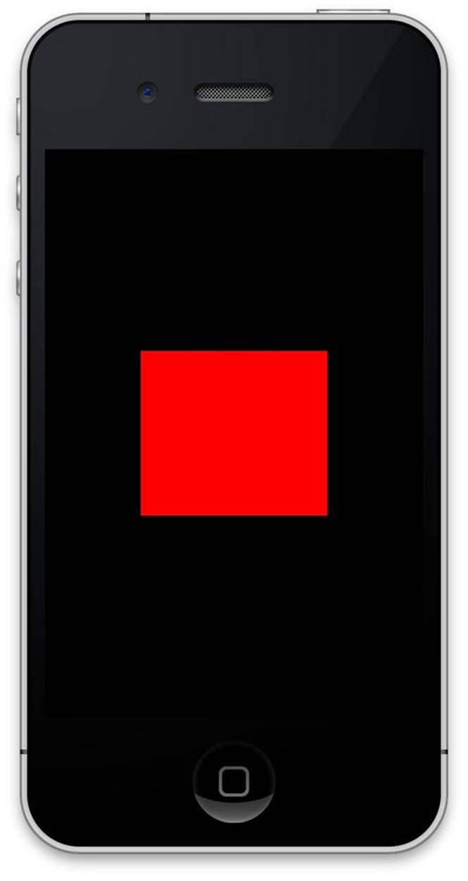
Figure 8-4. A square being drawn by OpenGL
Loading a Texture
Problem
You want to display a texture on an OpenGL surface.
Solution
In this solution, we’ll be loading a texture and applying it to the square that was drawn in the previous recipe.
First, in your vertex structure, you need to include texture coordinate information:
typedef struct {
GLKVector3 position; // the location of each vertex in space
GLKVector2 textureCoordinates; // the texture coordinates for each vertex
} Vertex;
const Vertex SquareVertices[] = {
{{-1, -1 , 0}, {0,0}}, // bottom left
{{1, -1 , 0}, {1,0}}, // bottom right
{{1, 1 , 0}, {1,1}}, // top right
{{-1, 1 , 0}, {0,1}}, // top left
};
Next, when preparing for rendering in viewDidLoad:
NSString* imagePath = [[NSBundle mainBundle]
pathForResource:@"Texture" ofType:@"png"];
NSError* error = nil;
GLKTextureInfo* texture = [GLKTextureLoader
textureWithContentsOfFile:imagePath options:nil error:&error];
if (error != nil) {
NSLog(@"Problem loading texture: %@", error);
}
_squareEffect.texture2d0.name = texture.name;
If you’re modifying the previous recipe, remove these lines:
_squareEffect.useConstantColor = YES;
_squareEffect.constantColor = GLKVector4Make(1.0, 0.0, 0.0, 1.0);
Finally, when rendering in glkView:drawInRect:, you indicate to OpenGL where to find texture coordinates in the vertex information:
glEnableVertexAttribArray(GLKVertexAttribTexCoord0);
glVertexAttribPointer(GLKVertexAttribTexCoord0, 2, GL_FLOAT, GL_FALSE,
sizeof(Vertex), (void*)offsetof(Vertex, textureCoordinates));
When the square is rendered, you’ll see your image appear on it.
Discussion
GLKTextureLoader allows you to take an image and upload it to the graphics chip that’s built into your device. To get an image, you use the pathForResource:ofType: method on NSBundle, which gives you the location of the image that you specify.
Once you’ve got that location, you pass it to GLKTextureLoader using the textureWithContentsOfFile:options:error: method. This sends the image to the graphics chip, and returns a GLKTextureInfo object. This object contains information about the texture, including its name.
In OpenGL, a texture’s name is a number used to identify that specific texture. To use a texture, you provide its name to the GLKEffect that you’re using to render your geometry.
In addition to loading a texture, you need to indicate to OpenGL which parts of the texture are attached to the geometry you’re drawing. This is done by defining texture coordinates.
Texture coordinates indicate points in the texture. As illustrated in Figure 8-5, the position (0,0) refers to the lower-left corner of the texture, while the position (1,1) refers to the upper-right corner.
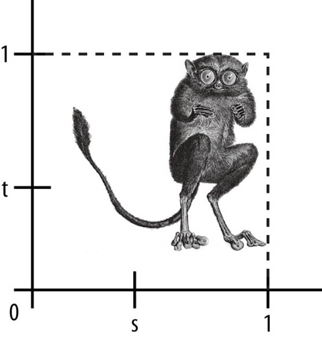
Figure 8-5. Texture coordinates
Texture coordinates are given to OpenGL by using the glEnableVertexAttribArray and glVertexAttribPointer functions. The first function tells OpenGL that you want to enable the use of texture coordinates, and the second tells OpenGL where in the vertex data the texture coordinates will be found (Figure 8-6).
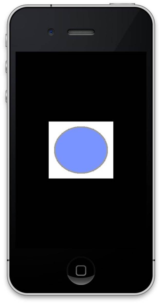
Figure 8-6. A textured square drawn by OpenGL
Drawing a Cube
Problem
You want to draw a three-dimensional cube, and draw a texture on its faces.
Solution
This solution builds from Loading a Texture.
A cube is made up of eight vertices, one for each of its corners. To draw the cube, therefore, you need to provide information for each vertex, including its position and texture coordinates.
Additionally, you’ll need to tell OpenGL how to build the triangles that make up each of the cube’s six faces. (Recall from Drawing a Square Using OpenGL that a square is drawn by drawing two triangles that share an edge.)
Note that in this example, we’ve renamed SquareVertices to CubeVertices and SquareTriangles to CubeTriangles:
const Vertex CubeVertices[] = {
{{-1, -1, 1}, {0,0}}, // bottom left front
{{1, -1, 1}, {1,0}}, // bottom right front
{{1, 1, 1}, {1,1}}, // top right front
{{-1, 1, 1}, {0,1}}, // top left front
{{-1, -1, -1}, {1,0}}, // bottom left back
{{1, -1, -1}, {0,0}}, // bottom right back
{{1, 1, -1}, {0,1}}, // top right back
{{-1, 1, -1}, {1,1}}, // top left back
};
const GLubyte CubeTriangles[] = {
0, 1, 2, // front face 1
2, 3, 0, // front face 2
4, 5, 6, // back face 1
6, 7, 4, // back face 2
7, 4, 0, // left face 1
0, 3, 7, // left face 2
2, 1, 5, // right face 1
5, 6, 2, // right face 2
7, 3, 6, // top face 1
6, 2, 3, // top face 2
4, 0, 5, // bottom face 1
5, 1, 0, // bottom face 2
};
The next step is a purely aesthetic one: the cube will be rotated, in order to illustrate that it is in fact a three-dimensional object.
Replace these lines:
GLKMatrix4 modelViewMatrix = GLKMatrix4MakeTranslation(0.0f, 0.0f, -6.0f);
_squareEffect.transform.modelviewMatrix = modelViewMatrix;
with the following:
GLKMatrix4 modelViewMatrix = GLKMatrix4MakeTranslation(0.0f, 0.0f, -6.0f);
modelViewMatrix = GLKMatrix4RotateX(modelViewMatrix,
GLKMathDegreesToRadians(45));
modelViewMatrix = GLKMatrix4RotateY(modelViewMatrix,
GLKMathDegreesToRadians(45));
_squareEffect.transform.modelviewMatrix = modelViewMatrix;
On its own, this is almost enough: as we saw in the previous recipe, the call to glDrawElements uses the size of the triangles array to determine how many triangles (and, consequently, how many vertices) it needs to use.
However, to draw our cube a depth buffer needs to be added and enabled.
Add this code immediately after the call to EAGLContext’s setCurrentContext method:
view.drawableDepthFormat = GLKViewDrawableDepthFormat24;
glEnable(GL_DEPTH_TEST);
Finally, replace this line:
glClear(GL_COLOR_BUFFER_BIT);
with this:
glClear(GL_COLOR_BUFFER_BIT | GL_DEPTH_BUFFER_BIT);
The result is shown in Figure 8-7.

Figure 8-7. A cube rendered in OpenGL
Discussion
A depth buffer is a region of memory that keeps track of how far away each pixel is from the camera. This makes it possible to draw, for example, a close object before drawing one further away—without a depth buffer, you’d need to make sure that you drew your farthest objects before drawing closer ones, or you’d end up with distant objects overlapping closer ones. If you want to learn more about this, check out the Wikipedia article on the Painter’s Algorithm.
Depth buffers work like this: every time a pixel is drawn onto the screen, OpenGL calculates how far away that pixel is from the camera. When the pixel is right up against the camera, a 0 is written into the depth buffer, and when the pixel is very, very far away from the camera, a 1 is written into the depth buffer. Pixels that fall somewhere between get written in as numbers in between (0.1, 0.12, and so on.)
When GL_DEPTH_TEST is turned on, OpenGL checks the depth buffer to see if the pixel it’s about to draw is further away than the most recently drawn pixel. If the pixel is closer to the camera than the nearest existing pixel, that means that it’s closer than the existing pixels, so it’s drawn on the screen and the distance of the new pixel replaces the old one in the depth buffer. However, if it’s further away than any existing pixel, it’s behind the old ones, and consequently it’s not drawn.
Just like with the color buffer, you have to clear the depth buffer every time you begin a new frame; if you don’t, you’ll end up with rendering glitches, because OpenGL will start comparing the depth values of pixels against an out-of-date depth buffer.
Rotating a Cube
Problem
You want to animate movement in a scene, such as rotation.
Solution
This solution builds upon the previous recipe.
Add the following instance variable to the ViewController class:
float rotation;
Next, add the following method to the class:
- (void) update {
// Find out how much time has passed since the last update
NSTimeInterval timeInterval = self.timeSinceLastUpdate;
// We want to rotate at 15 degrees per second, so multiply
// this amount times the time since the last update and
// update the "rotation" variable.
float rotationSpeed = 15 * timeInterval;
rotation += rotationSpeed;
// Now construct a model view matrix that places the object 6 units away
// from the camera and rotates it appropriately
GLKMatrix4 modelViewMatrix = GLKMatrix4MakeTranslation(0.0f, 0.0f, -6.0f);
modelViewMatrix = GLKMatrix4RotateX(modelViewMatrix,
GLKMathDegreesToRadians(45));
modelViewMatrix = GLKMatrix4RotateY(modelViewMatrix,
GLKMathDegreesToRadians(rotation));
// Apply this to the effect so that the drawing will use this positioning
_squareEffect.transform.modelviewMatrix = modelViewMatrix;
}
When you run the application, your cube will be rotating.
Discussion
The update method on a GLKViewController is called once per frame, and this is your game’s opportunity to update in-game content.
In this solution, we’re creating a GLKMatrix4, which defines the position and orientation of the object. You create it using the GLKMatrix4MakeTranslation function, and then rotate it around the x- and y-axes. Finally, the matrix is given to the object’s GLKEffect, which sets the position and orientation.
Moving the Camera in 3D Space
Problem
You want to be able to move the camera based on user input.
Solution
First, we’ll define how quickly the camera moves. Add the following line of code at the top of ViewController.m:
const float dragSpeed = 1.0f / 120.0f;
Next, add the following instance variable to ViewController:
GLKVector3 _cameraPosition;
Then add this code to the end of viewDidLoad:
UIPanGestureRecognizer* pan =
[[UIPanGestureRecognizer alloc] initWithTarget:self action:@selector(dragged:)];
[self.view addGestureRecognizer:pan];
_cameraPosition.z = -6;
Add this method to ViewController:
- (void) dragged:(UIPanGestureRecognizer*)pan {
if (pan.state == UIGestureRecognizerStateBegan ||
pan.state == UIGestureRecognizerStateChanged) {
CGPoint translation = [pan translationInView:pan.view];
_cameraPosition.x += translation.x * dragSpeed;
_cameraPosition.y -= translation.y * dragSpeed;
[pan setTranslation:CGPointZero inView:pan.view];
}
}
And finally, update this line in the update method:
GLKMatrix4 modelViewMatrix = GLKMatrix4MakeTranslation(0, 0, -6);
with this code:
GLKMatrix4 modelViewMatrix =
GLKMatrix4MakeTranslation(_cameraPosition.x, _cameraPosition.y,
_cameraPosition.z);
Discussion
The term “camera” in OpenGL is actually kind of a misnomer. In OpenGL, you don’t create a camera object and move it around; instead, the camera is always positioned at (0,0,0), and you position objects in front of it. In practical terms, this just means that the matrices that define the position and orientation of your objects need to be reversed—that is, when you want your object to be positioned 6 units in front of the camera, you set the z-position of the object to be –6.
NOTE
In Creating a Movable Camera Object, you’ll see how to create a movable camera in OpenGL.
All materials on the site are licensed Creative Commons Attribution-Sharealike 3.0 Unported CC BY-SA 3.0 & GNU Free Documentation License (GFDL)
If you are the copyright holder of any material contained on our site and intend to remove it, please contact our site administrator for approval.
© 2016-2026 All site design rights belong to S.Y.A.