iPhone Logic Board Repair (2016)
5. Repair practice
In the former chapters i have told how a the logic board works, the functions of its main components and the tools needed for repair and discussed the most common reasons for damage and defects. In this last chapter i would like to show defect assessment and repair in practice.
When a customer shows up with a defected iPhone the first question is ask myself is: Is this really a logic board issue or is it maybe something else? Therefore i first ask what happened just the before the malfunction occurred, and let the customer describe the problem. The history of the defect can you point you in the right direction.
“No touch” can mean logic board issues, or a just a faulty lcd screen. Therefore I first check the motherboard in a “known good housing”, with a “known good battery” (or the DCPS) and with a “known good screen”. If the problem persists than you can assume it is indeed logic board failure.
So:
1. Check history
2. Test in a known good housing, with a known good battery (or the DCPS) and with a known good screen.
The board problem can be a clear problem (like no touch) or a general problem (like no boot). For each I follow different approaches. I always first remove the shielding with hot air.
5.1. No power
If the board doesn’t power on I start with connecting the DCPS to see if it draws any energy (Amps) before trying to power it on. If it indeed consumes Amps at that point i know there is a major short probably on VCC_MAIN. In this case i follow the procedure described in 4.1. On the iPhone 6 many times the capacitor next to the Wi-Fi IC is to blame.
If there is no history of water damage, than probably the board suffered a fall resulting in cold solder under a IC. In this case i follow the procedure described in 4.3. I also inspect the board for cracked components or other (repair) damage. As a last resort i replace the charge IC.
There are more troubleshooting methods but those are lengthy and complicated. I believe these other methods are economically feasible for data recovery purposes only.
5.2. Specific problem
If the iPhone powers on normally, but (also) shows other malfunctions, I follow a different approach. If the problem is common like “no touch” or “no charge”. I replace the responsible IC for that function. Most of the times that solves the issue. If the problem is less common I start inspecting the board. If there is visible damage I just replace the damaged component. I also check the screw brackets for long screw damage. If a component needs to be replaced you have two options. First find a part supplier to order the component. The values are shown in the ZXW tool. Second: take components of a donerboard (a board beyond repair).
If I can’t locate the reason for the malfunction I start consulting the step by step solutions provided by https://itesla.solutions. These contain a screenshot (part) of the logic board with a step by step approach to test the components on the line(s) responsible for a specific function. For example for “no backlight” .The solutions start with the most easy to repair failing components, and move on to end with the hardest to repair components. I will conclude this e-book with outlining how to perform each of these tests. Most of the solutions take the following approach:
1. Test these filters
2. Test these capacitors
3. Test these resistors
4. Test the diode and/or the coil
5. Test these lines
6. Test these voltage
7. Replace these IC’s
8. Replace the PMIC
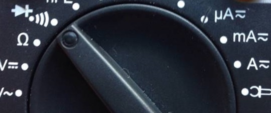
For testing filters and capacitors you set the multimeter to “continuity testing” (diode mode), usually it is pictured as follows. See the position of the knob. ![]() It is important to disconnect all power sources before try any testing as readings would not be correct. (Only for voltage testing the board needs to be powered on). To make reaching the smallest part easier I solder needles to the end of the two probes. One probe is negative (black) the other positive (red).
It is important to disconnect all power sources before try any testing as readings would not be correct. (Only for voltage testing the board needs to be powered on). To make reaching the smallest part easier I solder needles to the end of the two probes. One probe is negative (black) the other positive (red).
1. Testing filters ![]()
A good filter beeps (has continuity) when holding each probe simultaneously on each side of the filter. If it doesn’t beep it is faulty and needs to be replaced. If replacement isn’t possible the line needs to be jumped. This means a piece of (insulated) wire is attached from one point of the line to another to make the current in the line flow again. See this video for a example.
2. Testing capacitors![]()
If a capacitor beeps when holding each probe simultaneously on each side of the filter capacitor it can mean two things: the capacitor is faulty, or the line on which the capacitor seats is shorted GND. To find out you'll need remove the capacitor and test if it still beeps when it is removed. If it doesn’t beep it still can be faulty. But it doesn’t have to cause a malfunction. I keep it to this level of inspection. A good capacitor shouldn't beep.
3. Testing resistors ![]()
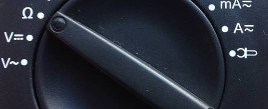
For testing a filter you set the multimeter to Ohm-mode![]() . For testing hold each probe simultaneously on each side of the resistor. The value shown on the multimeter should approach the value of the resistor. It is recommended to remove the resistor of board before testing. I do it while onboard.
. For testing hold each probe simultaneously on each side of the resistor. The value shown on the multimeter should approach the value of the resistor. It is recommended to remove the resistor of board before testing. I do it while onboard.
4. Testing diodes and/or coils /
/ 
This it often an important part for testing "no backlight".
Diode testing: put the multimeter to diode-mode ![]() .
.
Put black probe on the negative side of diode and red probe on the positive side . The multimeter should show the letters OL, if you test the black probe to the positive side of diode and red probe to the negative side of the diode it should have the value for the diode(usually between 200-400 Ohm).
This type of component must be soldered in the correct way, that is positive side of diode to the positive side of the line, and negative the same way.
Coil testing: put the multimeter to continuity-mode ![]() . It should beep when holding each probe simultaneously on each side of the coil.
. It should beep when holding each probe simultaneously on each side of the coil.
5. Testing lines
For testing lines you have to put the multimeter to continuity -mode ![]() . For this test I put one probe on a the active side of a capacitor (the opposite one of GND), and the other one on another active part of the line. You can see the connected components on the line using the ZXW tool.
. For this test I put one probe on a the active side of a capacitor (the opposite one of GND), and the other one on another active part of the line. You can see the connected components on the line using the ZXW tool.
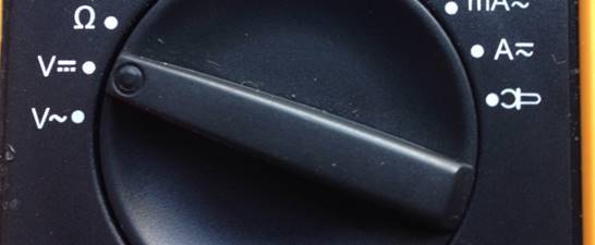
6. Testing voltages
For testing a voltages you set the multimeter to Voltage-mode ![]() . For this test the IPhone needs to be turned on. One probe needs to put on the active side of a voltage carrying capacitor, and the other probe on GND. The voltage should have the indicated value.
. For this test the IPhone needs to be turned on. One probe needs to put on the active side of a voltage carrying capacitor, and the other probe on GND. The voltage should have the indicated value.
7. Replacing a IC
For replacing a IC a hot air station is needed. A complicating factor is that some IC’s have epoxy under fill and ripping off pads under a IC sometimes happens. If the missing pad is active you have to find a way to jump it. It can also be a NON CONNECTED pad (NC). In that case you can go without. The ZXW tool can be used to determine if the pad needs to be jumped. Jumping the pad involves most of the time trace repair. These repairs demand high skill.

For removing the IC hot air is blown onto the ic. Personally I use 380 ° Celsius with a light air flow. Its surrounding often need be protected against the heat. Best practice is heat resistant tape and some coins used as heat sinks. There is a danger of accidently moving other components causing new malfunctions. This mostly happens in the direct surroundings of the ic or on the opposite side of the ic on the other side of the board.
After lifting the IC old solder on the pads on the board, and on IC itself needs to be removed. When using braid there is a danger of accidently ripping of pads. The best way to remove old solder is using a royally tinned well heated soldering iron.
In most cases the IC can be reused. Then it needs to reballed. For reballing a stencil and solder paste is used. See this video for the reaballing process.
The IC needs to be replaced in the same position it came off. The ZXW tool is able to show the right position.
For replacing the IC some flux is needed. Then the IC to is heated until the solder balls melt. Most of times you can see the IC falling nicely in to place when the melted balls the solder of the board pads. A little tap on the side of the IC when the solder is still liquid confirms proper positioning. See this video.
The PMIC ic is a little harder to reinstall because of it’s size and it’s tricky position on some boards.
5.3 Further reading
In this book I shown the basics of IPhone logic board repair. As I said in the beginning three basis things are needed for successful repair: tools, knowledge and experience. I hope I’ve succeeded in providing ways to source the right tools and knowledge. When it comes to experience: that will take time and practice. When you are looking for a good mentor i would advise you to become a member of https://itesla.solutions. And I would love to invite you to my YouTube channel. Some further reading:
For basic soldering I would advise the book: the basis soldering guide
And for general iPhone repair: The Unauthorized Guide to iPhone, iPad, and iPod Repair: A DIY Guide to Extending the Life of Your iDevices!
All materials on the site are licensed Creative Commons Attribution-Sharealike 3.0 Unported CC BY-SA 3.0 & GNU Free Documentation License (GFDL)
If you are the copyright holder of any material contained on our site and intend to remove it, please contact our site administrator for approval.
© 2016-2025 All site design rights belong to S.Y.A.