Unity in Action: Multiplatform game development in C# with Unity 5 (2015)
Part 2. Getting comfortable
Chapter 6. Putting a 2D GUI in a 3D game
This chapter covers
· Comparing old (pre-Unity 4.6) and new GUI systems
· Creating a canvas for the interface
· Positioning UI elements using anchor points
· Adding interactivity to the UI (buttons, sliders, and so on)
· Broadcasting and listening for events from the UI
In this chapter you’ll build a 2D interface display for a 3D game. So far, we’ve focused on the virtual scene itself while building a first-person demo. But every game needs abstract interaction and information displays in addition to the virtual scene the gameplay takes place in. This is true for all games, whether 2D or 3D, first-person shooter or puzzle game.
These abstract interaction displays are referred to as the UI, or more specifically the GUI. GUI refers to the visual part of the interface, such as text and buttons (see figure 6.1). Technically, the UI includes nongraphical controls, such as the keyboard or gamepad, but people tend to be referring to the graphical parts when they say “user interface.”
Figure 6.1. The GUI (a heads-up display, or HUD) you’ll create for a game
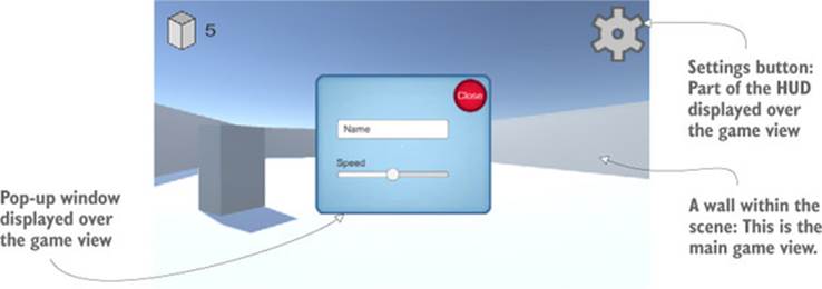
Although any software requires some sort of UI in order for the user of that software to control it, games often use their GUI in a slightly different way from other software. In a website, for example, the GUI basically is the website (in terms of visual representation). In a game, though, text and buttons are often an additional overlay on top of the game view, a kind of display called a HUD.
Definition
A heads-up display (HUD) superimposes graphics on top of the view of world. The concept of a HUD originated with military jets so that pilots could see crucial information without having to look down. Similarly, a GUI superimposed on the game view is referred to as the HUD.
This chapter will show how to build the game’s HUD using the latest UI tools in Unity. As you saw in chapter 5, Unity provides multiple ways to create UI displays. This chapter demonstrates the new UI system available with Unity 4.6 and later. I’ll also discuss the previous UI system and the advantages of the new system.
To learn about the UI tools in Unity, you’ll build on top of the first-person shooter (FPS) project from chapter 3. The project in this chapter will involve these steps:
1. Planning the interface
2. Placing UI elements on the display
3. Programming interactions with the UI elements
4. Making the GUI respond to events in the scene
5. Making the scene respond to actions on the GUI
Note
This chapter is largely independent of the project you build on top of—it just adds a graphical interface on top of an existing game demo. All the examples in this chapter are built on top of the FPS created in chapter 3, and you could download that sample project, but you’re free to use whatever game demo you’d like.
Copy the project from chapter 3 and open the copy to start working on this chapter. As usual, the art assets you need are in the sample download. With those files set up, you’re ready to start building the game’s UI.
6.1. Before you start writing code...
To start building the HUD, you first need to understand how the UI system works. Unity provides multiple approaches to building a game’s HUD, so we need to go over how those systems work. Then we can briefly plan the UI and prepare the art assets that we’ll need.
6.1.1. Immediate mode GUI or advanced 2D interface?
From its first version, Unity came with an immediate mode GUI system, and that system makes it easy to put a clickable button on the screen. Listing 6.1 shows the code to do that; simply attach this script to any object in the scene. For another example of immediate mode UI, recall the target cursor displayed in chapter 3. This GUI system is entirely based on code, with no work in Unity’s editor.
Definition
Immediate mode refers to explicitly issuing draw commands every frame, versus a system where you define all the visuals once and then for every frame the system knows what to draw without you having to tell it again. The latter approach is called retained mode.
Listing 6.1. Example of a button using the immediate mode GUI
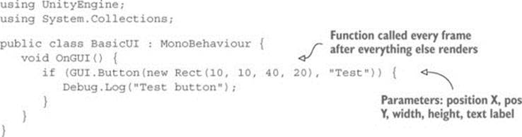
The core of the code in this listing is the OnGUI() method. Much like Start() and Update(), every MonoBehaviour automatically responds to OnGUI(). That function runs every frame after the 3D scene is rendered, providing a place to put GUI drawing commands. This code draws a button; note that the command for a button is executed every frame (that is, in immediate mode style). The button command is used in a conditional that responds when the button is clicked.
Because the immediate mode GUI makes it easy to get a few buttons onscreen with a minimum of effort, we’ll use it for examples in future chapters (especially chapter 8). But making default buttons is about the only thing easy to create with that system, so the latest versions of Unity now have a new interface system based on 2D graphics laid out in the editor. It takes a bit more effort to set up, but you’ll probably want to use the newer interface system in finished games because it produces more polished results.
The new UI system works in retained mode, so the graphics are laid out once and then drawn every frame without needing to be continually redefined. In this system, graphics for the UI are placed in Unity’s editor. This provides two advantages over the immediate mode UI: 1) you can see what the UI looks like while placing UI elements, and 2) this system makes it straightforward to customize the UI with your own images.
To use this system you’re going to import images and then drag objects into the scene. Next let’s plan how this UI will look.
6.1.2. Planning the layout
The HUD for most games is only a few different UI controls repeated over and over. That means this project doesn’t need to be a terribly complex UI in order for you to learn how to build a game’s UI. You’re going to put a score display and a settings button in the corners of the screen (seefigure 6.2) over the main game view. The settings button will bring up a pop-up window, and that window will have both a text field and a slider.
Figure 6.2. Planned GUI
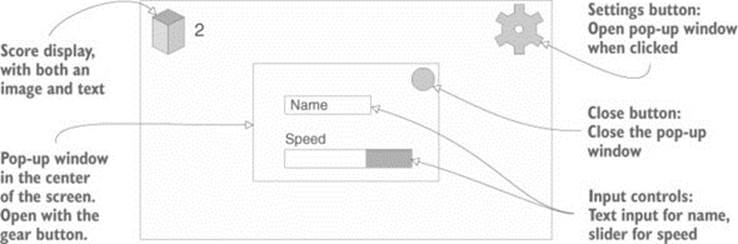
For this example, those input controls will be used for setting the player’s name and movement speed, but ultimately those UI elements could control any settings relevant to your game.
Well, that plan was pretty simple! The next step is bringing in the images that are needed.
6.1.3. Importing UI images
This UI requires some images to display for things like buttons. The UI is built from 2D images like the graphics in chapter 5, so you’ll follow the same two steps:
1. Import images (if needed, set them to Sprite).
2. Drag the sprites into the scene.
To accomplish these steps, first drag the images into Project view to import them, and then in the Inspector change their Texture Type setting to Sprite (2D And UI).
Warning
The Texture Type setting defaults to Texture in 3D projects and to Sprite in 2D projects. If you want sprites in a 3D project, you need to adjust this setting manually.
Get all the needed images from the sample download (see figure 6.3) and then import the images into your project. Make sure all the imported assets are set to Sprite; you’ll probably need to adjust Texture Type in the settings displayed after importing.
Figure 6.3. Images that are needed for this chapter’s project
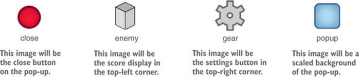
These sprites comprise the buttons, score display, and pop-up that you’ll create. Now that the images are imported, let’s put these graphics onto the screen.
6.2. Setting up the GUI display
The art assets are the same kind of 2D sprites we used in chapter 5, but the use of those assets in the scene is a bit different. Unity provides special tools to make the images a HUD that’s displayed over the 3D scene, rather than displaying the images as part of the scene. The positioning of UI elements also has some special tricks, because of the needs of a display that may change on different screens.
6.2.1. Creating a canvas for the interface
One of the most fundamental and nonobvious aspects of how the UI system works is that all images must be attached to a canvas object.
Tip
Canvas is a special kind of object that Unity renders as the UI for a game.
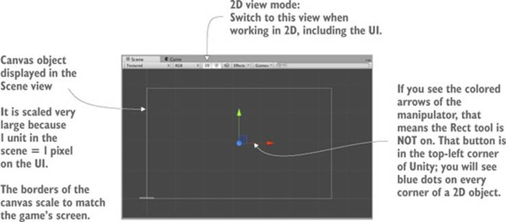
Open the GameObject menu to see the various kinds of objects you can create; in the UI category, choose Canvas. A canvas object will appear in the scene (it may be clearer to rename the object HUD Canvas). This object represents the entire extent of the screen, and it’s huge relative to the 3D scene because it scales one pixel of the screen to one unit in the scene.
Warning
When you create a canvas object, an EventSystem object is automatically created, too. That object is required for UI interaction but you can otherwise ignore it.
Switch to 2D view mode (refer to figure 6.4) and double-click the canvas in the Hierarchy in order to zoom out and view it fully. The 2D view mode is automatic when the entire project is 2D, but in a 3D project this toggle must be clicked to switch between the UI and the main scene. To return to viewing the 3D scene, toggle the 2D view mode off and then double-click the building to zoom to that object.
Figure 6.4. A blank canvas object in the Scene view
Tip
Don’t forget this tip from chapter 4: across the top of the Scene view’s pane are buttons that control what’s visible, so look for the Effects button to turn off the skybox.
The canvas has a number of settings that you can adjust. First is the Render Mode option; leave this at the default setting, but you should know what the three possible settings mean:
· Screen Space—Overlay —Renders the UI as 2D graphics on top of the camera view (this is the default setting).
· Screen Space—Camera —Also renders the UI on top of the camera view, but UI elements can rotate for perspective effects.
· World Space —Places the canvas object within the scene, as if the UI were part of the 3D scene.
The two modes besides the initial default can sometimes be useful for specific effects but are slightly more complicated.
The other important setting is Pixel Perfect. This setting causes the rendering to subtly adjust the position images so that they’re always perfectly crisp and sharp (as opposed to blurring them when positioned between pixels). Go ahead and select that check box. Now the HUD canvas is set up, but it’s still blank and needs sprites.
6.2.2. Buttons, images, and text labels
The canvas object defines an area to display as the UI, but it still requires sprites to display. If you refer back to the UI mockup in figure 6.2, there’s an image of the block/enemy in the top-left corner, text displaying the score next to that, and a gear-shaped button in the top-right corner. Accordingly, in the UI section of the GameObject menu are options to create an image, text, or button. Create one of each.
UI elements need to be a child of the canvas object in order to display correctly. Unity does this automatically, but remember that as usual you can drag objects around the Hierarchy view (see figure 6.5) to make parent-child linkages.
Figure 6.5. Canvas with an image linked in the Hierarchy view
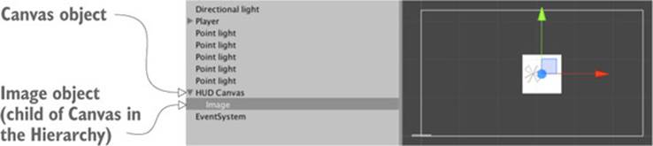
Objects within the canvas can be parented together for positioning purposes, just like any other objects in the scene. For example, you may want to drag the text object onto the image so that the text will move with the image. Similarly, the default button object has a text object as its child; this button doesn’t need a text label, so delete the text object.
Roughly position the UI elements into their corners. In the next section we’ll make the positions exact; for now, just drag the objects until they’re pretty much in position. Click and drag the image object to the top-left of the canvas; the button goes in the top right.
Tip
As noted in chapter 5, you use the Rect tool in 2D mode. I described it as a single manipulation tool that encompasses all three transforms: Move, Rotate, and Scale. These operations have to be separate tools in 3D but are combined in 2D because that’s one less dimension to worry about. In 2D mode, this tool is selected automatically, or you can click the button in the top-left corner of Unity.
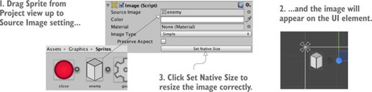
At the moment the images are both blank. If you select a UI object and look at the Inspector, you should see a Source Image slot near the top of the image component. As shown in figure 6.6, drag over sprites (remember, not textures!) from the Project view to assign images to the objects. Assign the enemy sprite to the image object, and the gear sprite to the button object (click Set Native Size after assigning sprites to properly size the image object).
Figure 6.6. Assign 2D sprites to the Image property of UI elements.
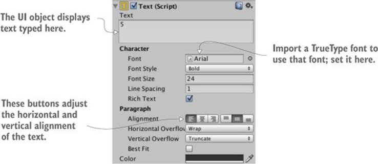
That took care of the appearance of both the enemy image and the gear button. As for the text object, there are a bunch of settings in the Inspector. First, type a single number in the large Text box; this text will be overwritten later, but it’s useful because it looks like a score display within the editor. The text is small, so increase the Font Size to 24 and make the style Bold. You also want to set this label to left horizontal alignment (see figure 6.7) and middle vertical alignment. For now the remaining settings can be left at their default values.
Figure 6.7. Settings for a UI text object
Note
Besides the Text box and alignment, the most common property to adjust is the font. You can import a TrueType font into Unity, and then put that font in the Inspector.
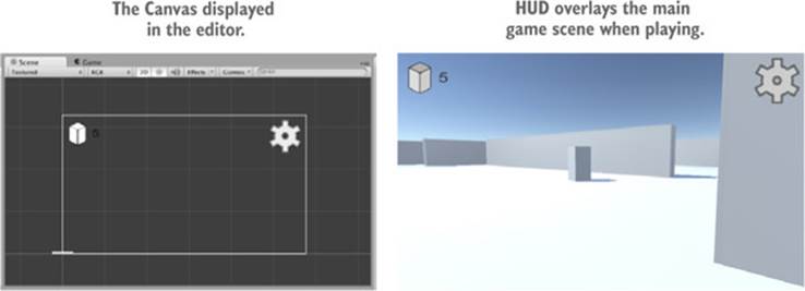
Now that sprites have been assigned to the UI images, and the score text is set up, you can hit Play to see the HUD on top of the 3D game. As shown in figure 6.8, the canvas displayed in Unity’s editor shows the bounds of the screen, and UI elements are drawn onto the screen in those positions.
Figure 6.8. The GUI as seen in the editor (left) and when playing the game (right)
Great, you made a HUD with 2D images displayed over the 3D game! One more complex visual setting remains: positioning UI elements relative to the canvas.
6.2.3. Controlling the position of UI elements
All UI objects have an anchor, displayed in the editor as a target X (see figure 6.9). An anchor is a flexible way of positioning objects on the UI.
Figure 6.9. The anchor point of an image object
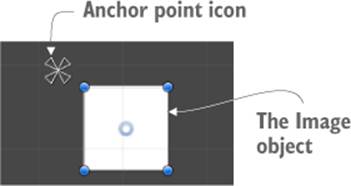
Definition
The anchor of an object is the point where an object attaches to the canvas or screen. It determines what that object’s position is measured relative to.
Positions are values like “50 pixels on the X-axis.” But that leaves the question: 50 pixels from what? This is where anchors come in. The purpose of an anchor is that while the object stays in place relative to the anchor point, the anchor moves around relative to the canvas. The anchor is defined as something like “center of the screen,” and then the anchor will stay centered while the screen changes size. Similarly, setting the anchor to the right side of the screen will keep the object rooted to the right side even if the screen changes size (for example, if the game is played on different monitors).
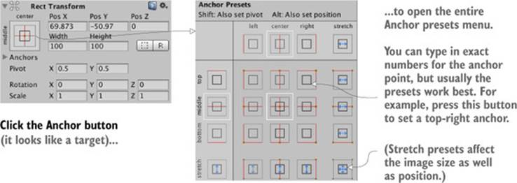
The easiest way to understand what I’m talking about is to see it in action. Select the image object and look over at the Inspector. Anchor settings (see figure 6.10) will appear right below the transform component. By default, UI elements have their anchor set to Center, but you want to set the anchor to Top Left for this image; figure 6.10 shows how to adjust that using the Anchor Presets.
Figure 6.10. How to adjust anchor settings
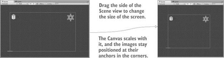
Change the gear button’s anchor as well. Set it to Top Right for this object; click the top-right Anchor Preset. Now try scaling the window left and right; click and drag on the side of the Scene view. Thanks to the anchors, the UI objects will stay in their corners while the canvas changes size. As figure 6.11 shows, these UI elements are now rooted in place while the screen moves.
Figure 6.11. Anchors stay in place while the screen changes.
Tip
Anchor points can adjust scale as well as position. We’re not going to explore that functionality in this chapter, but each corner of the image can be rooted to a different corner of the screen. In figure 6.11 the images didn’t change size, but we could adjust the anchors so that when the screen changes size, the image stretches with it.
All of the visual setup is done, so it’s time to program interactivity.
6.3. Programming interactivity in the UI
Before you can interact with the UI, you need to have a mouse cursor. If you recall, this game adjusted Cursor settings in the Start() method of the RayShooter code. Those settings lock and hide the mouse cursor, a behavior that works for the controls in an FPS game but that interferes with using the UI. Remove those lines from RayShooter.cs so that you can click on the HUD.
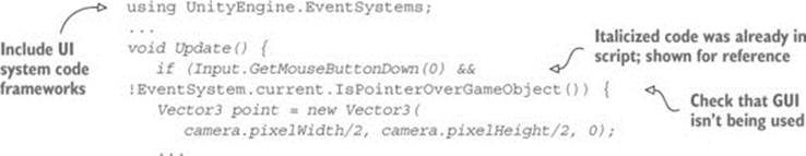
As long as you have RayShooter.cs open, you could also make sure not to shoot while interacting with the GUI. The following listing shows the code for that.
Listing 6.2. Adding a GUI check to the code in RayShooter.cs
Now you can play the game and click the button, although it doesn’t do anything yet. You can watch the tinting of the button change as you mouse over it and click. This mouseover and click behavior is a default tint that can be changed for each button, but the default looks fine for now. You could speed up the default fading behavior; Fade Duration is a setting in the button component, so try decreasing that to .01 to see how the button changes.
Tip
Sometimes the default interaction controls of the UI also interfere with the game. Remember the EventSystem object that was created automatically along with the canvas? That object controls the UI interaction controls, and by default it uses the arrow keys to interact with the GUI. You may need to turn off the arrow keys in EventSystem: in the settings for EventSystem, deselect the check box Send Navigation Event.
But nothing else happens when you click the button because you haven’t yet linked it up to any code. Let’s take care of that next.
6.3.1. Programming an invisible UIController
In general, UI interaction is programmed with a standard series of steps that’s the same for all UI elements:
1. Create a UI object in the scene (the button created in the previous section).
2. Write a script to call when the UI is operated.
3. Attach that script to an object in the scene.
4. Link UI elements (such as buttons) to the object with that script.
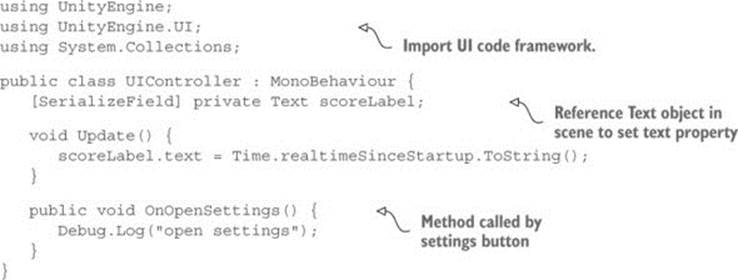
To follow these steps, first we need to create a controller object to link to the button. Create a script called UIController (shown in the following listing) and drag that script onto the controller object in the scene.
Listing 6.3. UIController script used to program buttons
Tip
You might be wondering why we need separate objects for Scene-Controller and UIController. Indeed, this scene is so simple that you could have one controller handling both the 3D scene and the UI. As the game gets more complex, though, it’ll become increasingly useful for the 3D scene and the UI to be separate modules, communicating indirectly. This notion extends well beyond games to software in general; software engineers refer to this principle as separation of concerns.
Now drag objects to component slots in order to wire them up. Drag the score label (the text object we created before) to the UIController’s text slot. The code in UIController sets the text displayed on that label. Currently the code displays a timer to test the text display; that will be changed to the score later.
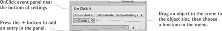
Next, add an OnClick entry to the button to drag the controller object onto. Select the button to see its settings in the Inspector. Toward the bottom you should see an OnClick panel; initially that panel is empty, but (as you can see in figure 6.12) you can click the + button to add an entry to that panel. Each entry defines a single function that gets called when that button is clicked; the listing has both a slot for an object and a menu for the function to call. Drag the controller object to the object slot, and then look for UIController in the menu; select OnOpenSettings() in that section.
Figure 6.12. The OnClick panel toward the bottom of the button settings
Responding to other mouse events
OnClick is the only event that the button component exposes, but UI elements can respond to a number of different interactions. To go beyond the default interactions, use an EventTrigger component.
Add a new component to the button object and look for the Event section of the component’s menu. Select EventTrigger from that menu. Although the button’s OnClick responded only to a full click (the mouse button being pressed down and then released), let’s try responding to the mouse button being pressed down but not released. Perform the same steps as for OnClick, only responding to a different event. First add another method to UIController:
...
public void OnPointerDown() {
Debug.Log("pointer down");
}
...
Now click Add New Event Type to add a new type to the EventTrigger component. Choose Pointer Down for the event. This will create an empty panel for that event, just like OnClick had. Click the + button to add an event listing, drag the controller object to this entry, and selectOnPointerDown() in the menu. There you go!
Play the game and click the button to output debug messages in the console. Again, the code is currently random output in order to test the button’s functionality. What we want to do is open a settings pop-up, so let’s create that pop-up window next.
6.3.2. Creating a pop-up window
The UI has a button to open a pop-up window, but there’s no pop-up yet. That will be a new image object, along with several controls (such as buttons and sliders) attached to that object. The first step is to create a new image, so choose GameObject > UI > Image. Just as before, the new image has a slot in the Inspector called Source Image. Drag a sprite to that slot to set this image. This time use the sprite called popup.
Ordinarily, the sprite is stretched over the entire image object; this was how the score and gear images worked, and you clicked the Set Native Size button to resize the object to the size of the image. This behavior is the default for image objects, but the pop-up will do something different.
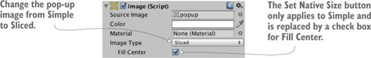
As you can see in figure 6.13, the image component has an Image Type setting. This setting defaults to Simple, which was the correct image type earlier. For the pop-up, though, set Image Type to Sliced.
Figure 6.13. Settings for the image component, including Image Type
Definition
A sliced image is split up into nine sections that scale differently from one another. By scaling the edges of the image separately from the middle, you ensure that the image can scale to any size you want while it maintains its sharp and crisp edges. In other development tools, these kinds of images often have “9” somewhere in the name (such as 9-slice, 9-patch, scale-9) to indicate the 9 sections of the image.
After you switch to a sliced image, Unity may display an error in the component settings, complaining that the image doesn’t have a border. That’s because the popup sprite doesn’t have the nine sections defined yet. To set that up, first select the popup sprite in the Project view. In the Inspector you should see a Sprite Editor button (see figure 6.14); click that button and the Sprite Editor window will appear.
Figure 6.14. Sprite Editor button in the Inspector and a pop-up window
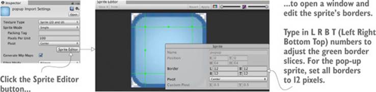
In the Sprite Editor you can see green lines that indicate how the image will be sliced. Initially the image won’t have any border (that is, all of the Border settings are 0). Increase the border width of all four sides, which will result in the border shown in figure 6.14. Because all four sides (Left, Right, Bottom, and Top) have the border set to 12 pixels wide, the border lines will overlap into nine sections. Close the editor window and apply the changes.
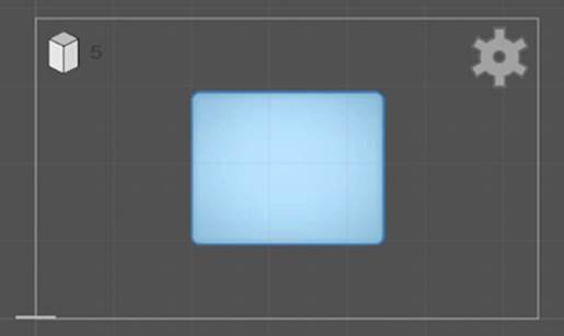
Now that the sprite has the nine sections defined, the sliced image will work correctly (and the Image component settings will show Fill Center; make sure that setting is on). Click and drag the blue indicators in the corner of the image to scale it (switch to the Rect tool described in chapter 5if you don’t see any scale indicators). The border sections will maintain their size while the center portion scales.
Because the border sections maintain their size, a sliced image can be scaled to any size and still have crisp edges. This is perfect for UI elements—different windows may be different sizes but should still look the same. For this pop-up, enter a width of 250 and a height of 200 to make it look like figure 6.15 (also, center it on position 0, 0, 0).
Figure 6.15. Sliced image scaled to dimensions of the pop-up
Tip
How UI images stack on top of each other is determined by their order in the Hierarchy view. In the Hierarchy list, drag the pop-up object above other UI objects (always staying attached to the canvas, of course). Now move the pop-up around within the Scene view; you can see how images overlap the pop-up window. Finally drag the pop-up to the bottom of the canvas hierarchy so that it will display on top of everything else.
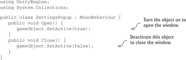
The pop-up object is set up now, so write some code for it. Create a script called SettingsPopup (see the next listing) and drag that script onto the pop-up object.
Listing 6.4. SettingsPopup script for the pop-up object
Next, open UIController.cs to make a few adjustments, as shown in the following listing.
Listing 6.5. Adjusting UIController to handle the pop-up
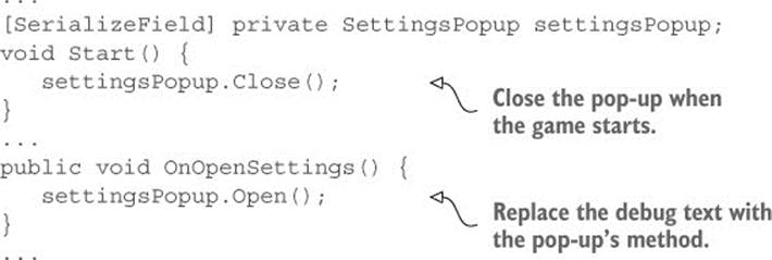
This code adds a slot for the pop-up object, so drag the pop-up to UIController. Now the pop-up will be closed initially when you play the game, and it’ll open when you click the settings button.
At the moment there’s no way to close it again, so add a close button to the pop-up. The steps are pretty much the same as for the button created earlier: choose GameObject > UI> Button, position the new button in the top-right corner of the pop-up, drag the close sprite to this UI element’s Source Image property, and then click Set Native Size to correctly resize the image. Unlike with the previous button we actually want this text label, so select the text and type Close in the text field, and set Color to white. In the Hierarchy view, drag this button onto the pop-up object so that it will be a child of the pop-up window. And as a final touch of polish, adjust the button transition to a Fade Duration value of .01 and a darker Normal Color setting of 110, 110, 110, 255.
To make the button close the pop-up, it needs an OnClick entry; click the + button on the button’s OnClick panel, drag the pop-up window into the object slot, and choose Close() from the function list. Now play the game and this button will close the pop-up window.
The pop-up window has been added to the HUD. The window is currently blank, though, so let’s add some controls to it next.
6.3.3. Setting values using sliders and input fields
Adding some controls to the settings pop-up involves two main steps, like the buttons we made earlier. You create UI elements attached to the canvas, and link those objects to a script. The input controls we need are a slider and a text field, and there will be a static text label to identify the slider. Choose GameObject > UI > Text to create the text object, GameObject > UI > InputField to create the text field, and GameObject > UI > Slider to create the slider object (see figure 6.16).
Figure 6.16. Input controls added to the pop-up window
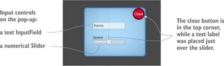
Make all three objects children of the pop-up by dragging them in the Hierarchy view and then position them as indicated in the figure, lined up in the middle of the pop-up. Set the text to Speed so that it can be a label for the slider. The input field is for typing in text, and Text is shown in the box before the player types something else; set this value to Name. You can leave the options Content Type and Line Type at their defaults; if desired, you can use Content Type to restrict typing to things like only letters or only numbers, whereas you can use Line Type to switch from a single line to multiline text.
Warning
You won’t be able to click the slider if the text label covers it. Make sure the text object appears under the slider by placing it above the slider in the Hierarchy.
As for the slider itself, several settings appear toward the bottom of the component inspector. Min Value is set to 0 by default; leave that. Max Value defaults to 1, but make it 2 for this example. Similarly, both Value and Whole Numbers can be left at their defaults; Value controls the starting value of the slider, and Whole Numbers constrains it to 0 1 2 rather than decimal values (a constraint we don’t want).
And that wraps up all the objects. Now you need to write the code that the objects are linked to; add the methods shown in the following listing to SettingsPopup.cs.
Listing 6.6. SettingsPopup methods for the pop-up’s input controls
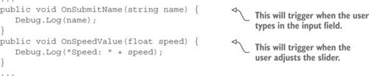
Great, there are methods for the controls to use. Starting with the input field, in settings you’ll see an End Edit panel; events listed here are triggered when the user finishes typing. Add an entry to this panel, drag the pop-up to the object slot, and choose OnSubmitName() in the function list.
Warning
Be sure to select the function in the End Edit panel’s top section, Dynamic String, and not the bottom section, Static Parameters. The OnSubmitName() function appears in both sections, but selecting it under Static Parameters will send only a single string defined ahead of time; dynamic string refers to whatever value is typed in the input field.
Follow these same steps for the slider: look for the event panel toward the end of the component settings (in this case, the panel is OnValueChanged), click + to add an entry, drag in the settings pop-up, and choose OnSpeedValue() in the list of dynamic value functions.
Now both of the input controls are connected to code in the pop-up’s script. Play the game, and watch the console while you move the slider or press Enter after typing input.
Saving settings between plays using PlayerPrefs
A few different methods are available for saving persistent data in Unity, and one of the simplest is called PlayerPrefs. Unity provides an abstracted way (that is, you don’t worry about the details) to save small amounts of information that works on all platforms (with their differing filesystems). PlayerPrefs aren’t too useful for large amounts of data (in chapter 11 we’ll use other methods to save the game’s progress), but they’re perfect for saving settings.
PlayerPrefs provide simple commands to get and set named values (it works a lot like a hash table or dictionary). For example, you can save the speed setting by adding the line PlayerPrefs.SetFloat("speed", speed); inside the OnSpeedValue() method of the SettingsPopup script. That method will save the float in a value called speed.
Similarly, you’ll want to initialize the slider to the saved value. Add the following code to SettingsPopup:
using UnityEngine.UI;
...
[SerializeField] private Slider speedSlider;
void Start() {
speedSlider.value = PlayerPrefs.GetFloat("speed", 1);
}
...
Note that the get command has both the value to get as well as a default value in case speed wasn’t previously saved.
Although the controls generate debug output, they still don’t actually affect the game. Making the HUD affect the game (and vice versa) is the topic of the final section of this chapter.
6.4. Updating the game by responding to events
Up to now, the HUD and main game have been ignoring each other, but they ought to be communicating back and forth. That could be accomplished via script references as we’ve done for other sorts of interobject communication, but that approach would have major downsides. In particular, doing so would tightly couple the scene and the HUD; you want to keep them fairly independent from each other so that you can freely edit the game without worrying that you’ve broken the HUD.
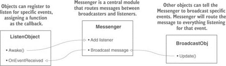
To alert the UI of actions in the scene, we’re going to make use of a broadcast messenger system. Figure 6.17 illustrates how this event messaging system works: scripts can register to listen for an event, other code can broadcast an event, and listeners will be alerted about broadcast messages. Let’s go over a messaging system to accomplish that.
Figure 6.17. Diagram of the broadcast event system we’ll implement
Tip
C# does have a built-in system for handling events, so you might wonder why we don’t use that. Well, the built-in event system enforces targeted messages, whereas we want a broadcast messenger system. A targeted system requires the code to know exactly where messages originate from; broadcasts can originate from anywhere.
6.4.1. Integrating an event system
To alert the UI of actions in the scene, we’re going to make use of a broadcast messenger system. Although Unity doesn’t have this feature built in, a great script for this purpose exists online. Among the resources listed in appendix D is the Unify community wiki; this is a repository of free code contributed by other developers. Their messenger system is great for providing a decoupled way of communicating events to the rest of the program. When some code broadcasts a message, that code doesn’t need to know anything about the listeners, allowing for a great deal of flexibility in switching around or adding objects.
Create a script called Messenger and paste in the code from this page on Unify: http://wiki.unity3d.com/index.php/CSharpMessenger_Extended
Then you also need to create a script called GameEvent (see the following listing).
Listing 6.7. GameEvent script to use with Messenger
public static class GameEvent {
public const string ENEMY_HIT = "ENEMY_HIT";
public const string SPEED_CHANGED = "SPEED_CHANGED";
}
The script in the listing defines a constant for a couple of event messages; the messages are more organized this way, and you don’t have to remember and type the message string all over the place.
Now the event messenger system is ready to use, so let’s start using it. First we’ll communicate from the scene to the HUD, and then we’ll go in the other direction.
6.4.2. Broadcasting and listening for events from the scene
Up to now the score display has displayed a timer as a test of the text display functionality. But we want to display a count of enemies hit, so let’s modify the code in UIController. First delete the entire Update() method, because that was the test code. When an enemy dies, it will emit an event, so the following listing makes UIController listen for that event.
Listing 6.8. Adding event listeners to UIController
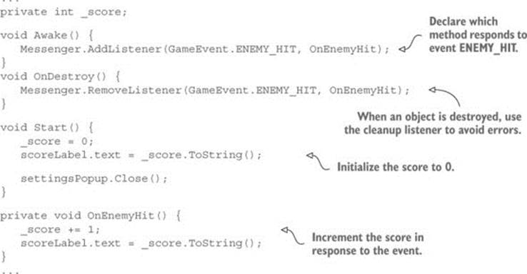
First notice the Awake() and OnDestroy() methods. Much like Start() and Update(), every MonoBehaviour automatically responds when the object awakes or is removed. A listener gets added and removed in Awake()/OnDestroy(). This listener is part of the broadcast messaging system, and it calls OnEnemyHit() when that message is received. OnEnemyHit()increments the score and then puts that value in the score display.
The event listeners are set up in the UI code, so now we need to broadcast that message whenever an enemy is hit. The code to respond to hits is in RayShooter.cs, so emit the message as shown in the following listing.
Listing 6.9. Broadcast event message from RayShooter
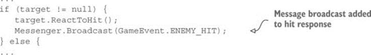
Play the game after adding that message and watch the score display when you shoot an enemy. You should see the count going up every time you make a hit. That covers sending messages from the 3D game to the 2D interface, but we also want an example going in the other direction.
6.4.3. Broadcasting and listening for events from the HUD
In the previous section, an event was broadcast from the scene and received by the HUD. In a similar way, UI controls can broadcast a message that both players and enemies listen for. In this way, the settings pop-up can affect the settings of the game. Open WanderingAI.cs and add the code from the next listing.
Listing 6.10. Event listener added to WanderingAI
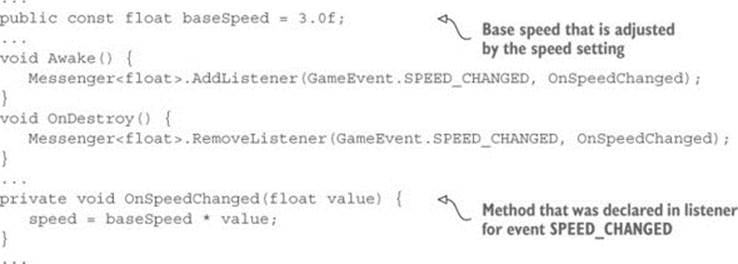
Awake() and OnDestroy() add and remove, respectively, an event listener here, too, but the methods have a value this time. That value is used to set the speed of the wandering AI.
Tip
The code in the previous section just used a generic event, but this messaging system can pass a value along with the message. Supporting a value in the listener is as simple as adding a type definition; note the <float> added to the listener command.
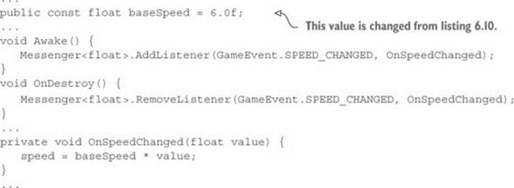
Now make the same changes in FPSInput.cs to affect the speed of the player. The code in the next listing is almost exactly the same as that in listing 6.10, except that the player has a different number for baseSpeed.
Listing 6.11. Event listener added to FPSInput
Finally, broadcast the speed values from SettingsPopup in response to the slider, as shown in the following listing.
Listing 6.12. Broadcast message from SettingsPopup

Now the enemy and player have their speed changed when you adjust the slider. Hit Play and try it out!
Exercise: Changing the speed of spawned enemies
Currently the speed value is only updated for enemies already in the scene and not for newly spawned enemies; new enemies aren’t created at the correct speed setting. I’ll leave it as an exercise for you to figure out how to set the speed on spawned enemies. Here’s a hint: add aSPEED_CHANGED listener to SceneController, because that script is where enemies are spawned from.
You now know how to build a graphical interface using the new UI tools offered by Unity. This knowledge will come in handy in all future projects, even as we explore different game genres.
6.5. Summary
In this chapter you’ve learned that
· Unity has both an immediate mode GUI system as well as a newer system based on 2D sprites.
· Using 2D sprites for a GUI requires that the scene have a canvas object.
· UI elements can be anchored to relative positions on the adjustable canvas.
· Set the Active property to turn UI elements on and off.
· A decoupled messaging system is a great way to broadcast events between the interface and the scene.
All materials on the site are licensed Creative Commons Attribution-Sharealike 3.0 Unported CC BY-SA 3.0 & GNU Free Documentation License (GFDL)
If you are the copyright holder of any material contained on our site and intend to remove it, please contact our site administrator for approval.
© 2016-2026 All site design rights belong to S.Y.A.