Biologically Inspired Computer Vision (2015)
Part II
Sensing
Chapter 6
Bioinspired Optical Imaging
Mukul Sarkar
6.1 Visual Perception
Among the senses that help perceive the world around, vision plays a larger role for humans, as well as for many other animals. Vision provides veridical perception (from the Latin veridicus, truthful) about the environment and thus helps in successful survival without actual contact with the environment. Vision, however, would not have any meaning without the presence of light. Light is an electromagnetic radiation that travels in the form of waves. Visual perception is the ability to detect light and interpret it to acquire knowledge about the environment. Knowledge thus acquired helps in survival by properly interpreting objects inherent to the environment.
The early explanation of vision was provided by two major ancient Greek schools of thought. One believed in the “emission theory” championed by scholars such as Euclid and Ptolemy, according to which vision occurs when light rays emanate from the eyes and are intercepted by visual objects. The other school championed by scholars such as Aristotle and Galen believed in “intromission” where vision occurs by something entering the eyes representative of the object [1]. The Persian scholar Ibn al-Haytha, (“Alhazen”) is credited for refining the intromission theory into the modern accepted theory of perception of vision [2]. In his most influential “Book of Optics,” he defines vision to be due to the light from objects entering the eye [3, 4].
Perception is unavoidably selective; one cannot see all there is to see. Visual perception is not merely a translation of retinal stimuli. It is more a way to understand the environment and use the information about the environment to help in survival. Eyes are the first step to visual perception. The eyes can be classified broadly into single-aperture eyes of humans and the compound eyes of insects. The compound eyes of insects in comparison to single-aperture eyes have a much wider field of view, better capability to detect moving objects, higher sensitivity to light intensity, but much lower spatial resolution. Compound eyes are the most compact vision systems found in nature. The visual perception of eyes differs from that of the camera in that cameras can only take pictures and need not know the objects whose pictures are being captured. When a conventional camera is used, only the picture information is captured, whereas eyes help in interpretation of the acquired image and thus help in knowing the environment. Insects, for example, have adapted their eyes to face environmental contingencies in a most efficient way in terms of utilization of resources and speed. Such systems are highly desirable in many machine vision applications. The principles of optical vision from natural systems can be used to build up a working artificial computer vision system for machine vision applications such as motion detection, object and gesture recognition, and so on
6.1.1 Natural Single-Aperture and Multiple-Aperture Eyes
Light is an important tool for visual perception. Most eyes experience light as having three features: color, brightness, and saturation. The color or hue of the light depends on its wavelength. The brightness of the light is related to the intensity of light the object emits or reflects. Intensity depends on the amplitude of the light wave. Saturation depends on the range of wavelengths in light. Figure 6.1 shows the light spectrum.
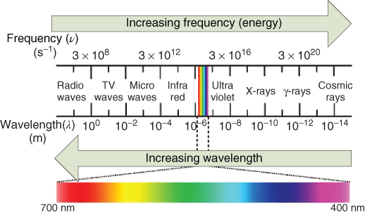
Figure 6.1 Light spectrum.
The visible spectrum is part of the light spectrum which includes the wavelength range from 400 nm to 700 nm. Wavelengths shorter than 400 nm are referred to as ultraviolet light, while wavelengths longer than 700 nm are referred to as infrared radiations.
Vision is perception of light. Light is perceived by means of optical systems, for example, eyes. Eyes can be simply defined as organs or visual systems for spatial vision. Eyes usually have millions of photoreceptors, which are specialized cells responding to light stimuli. The number of photoreceptors also defines the resolution of spatial vision. Spatial resolution defines how precisely objects in the environment can be differentiated. The higher the number of photoreceptors, the larger is the spatial resolution. This has been the inspiration behind human eyes, which have millions of photoreceptors. Higher spatial resolution can also be achieved by multiplying the visual system in its entirety [5] as observed in the eyes of insects. The insect's eyes are a compound of individual lenses, each with its own photoreceptor array. The single-aperture human eye and the compound eye of insects are shown in Figure 6.2.
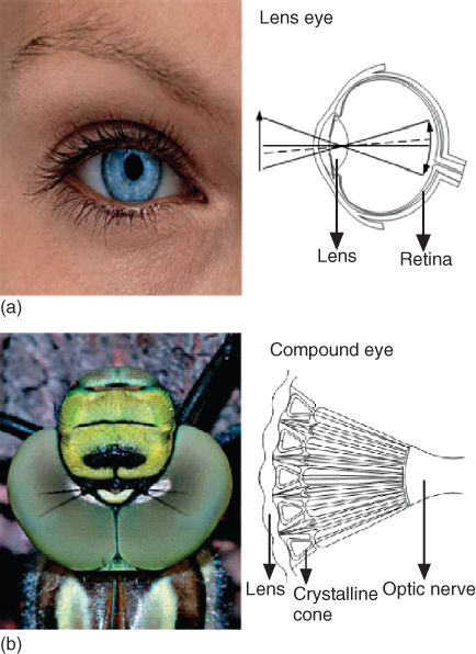
Figure 6.2 (a) Human eye, (b) Compound eye [6].
6.1.1.1 Human Eyes
Human eyes are also called “camera-type eyes.” The human eye focuses light on a light-sensitive membrane, the retina, just as a camera focuses light on a film. The human eye consists of two types of photoreceptors, rods and cones. On an average, there are 120 million rods and 6–7 million cones in the human eye. Rods are more sensitive to the intensity of light than are cones, but they have poor spectral (color) sensitivity, while cones provide spectral vision. The cones are divided into three colors – red, green, and blue – on the basis of their spectral sensitivity. The cones are responsible for high-resolution vision or visual acuity, whereas the rods are responsible for dark-adapted or scotopic vision. The sensitivity of the rods is very high and can be triggered by individual light photons [7]. The rods are thus better motion sensors.
6.1.1.2 Compound Eyes
Most insects have compound eyes with multiple light-gathering units known as ommatidia. Each ommatidia as shown in Figure 6.3 consists of a lens that forms an image on the tip of the light-sensitive visual cell rhabdom, a transparent crystalline cone to guide the light and absorptive pigment between the ommatidium [8]. The optical part of the ommatidium includes the corneal lens and the crystalline cone, while the sensory part includes the retinula cells and the rhabdom. The light-sensitive parts of the visual cells are microvillis, an array of tubelike membranes where the pigment rhodopsin is located. Photons are captured by the rhabdome. The rhabdomeres are highly refractive materials; the light entering them are totally internally reflected and they are thus ideal for collecting available light with minimal losses. This visual information is transduced into electrical signals by the photoreceptor cells at the level of the retina.
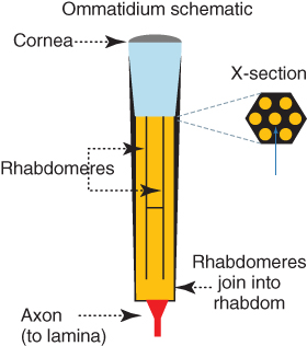
Figure 6.3 Ommatidia of a compound eye.
Compound eyes can broadly be classified into apposition and superposition types [9]. In an apposition eye, each optical channel has its own receptor. The acceptance angle of light in each ommatidium is low, thus preventing the spreading of light among adjacent ommatidia. Apposition eyes are generally found in day-active insects such as ants, wasps, dragonflies, bees and cockroaches. In a superposition compound eye, light from a different adjacent channel is guided to a common receptor. Superposition eyes are typically more sensitive to light, and this type is found mainly in animals that live under low light conditions.
Insects and humans have very different types of eyes, each having its advantages and disadvantages. The following are the basic differences between the human eye and insect's eye:
6.1.1.3 Resolution
The compound eye is made up of multiple smaller optical structures called ommatidia. The higher the number of ommatidia or optical units in an eye, the higher is the spatial resolution (defined as the ability of the eye to resolve fine details). In the human eye, a single lens covers the entire retina with many sensory cells, wherein each sensory cell works as an optical unit or pixel. The density of photoreceptors is around 25 times higher in the human eyes compared to the compound eye. This allows the human eye to have a greater spatial resolution of the object. For insects, in order to reach a similar spatial resolution, the lenses need to be extraordinarily large. The small lenses of the compound eye are diffraction limited. The small optics are not capable of focusing light onto to a small enough point, thus the overall resolution is degraded.
Contrast is the ability to distinguish similar shades of the same color. The contrast is related to the intensity of the light levels; in dim light the contrast is low and in bright light the contrast is high. To improve the contrast in a dim environment, either a large aperture is needed to allow more light to reach the visual elements or the light needs to be integrated over a larger period of time. The eyes of insects are limited by the small aperture of each ommatidium in the compound eye as well as the time for which the light can be integrated, as the response time in a dynamic environment is quite low. Human eyes are also not adapted for night vision.
6.1.1.4 Visual Acuity
Acuity, in human vision, is defined as the reciprocal of the minimum resolvable angle measured in minutes of arc [10]. Visual acuity is also used to describe the smallest single object or the smaller details in the object that an eye can detect. Visual acuity defines the actual spatial resolution that the eyes can perceive. The spatial density of retinal cells in human eyes and ommatidia in compound eyes determine the number of visualelements in the final image and thus determine the visual acuity. Visual acuity is affected by the imperfections and optical limits of the lens system. The eyes of insects are limited by diffraction of light. A single point of light coming from an object appears as a blurred spot in the final image. The visual acuity of the compound eye is about one-hundredth that of the human eye.
6.1.1.5 Depth Perception
The binocular cues and monocular cues are used by human eyes to estimate the distance of the objects in the visual scene. Binocular cues require both eyes. There are two types of binocular cues: retinal disparity and convergence. Retinal disparity marks the difference between the two images captured by the two eyes. Retinal disparity increases as the eyes get closer to an object. The differences in the images captured by the two retina spaced apart in space are used to estimate the distance between the viewer and the object being viewed. Convergence is when eyes turn inward to cross on an object at close up. The eye muscles tense to turn the eye and this tense information is interpreted to estimate the distance of the object.
Monocular cues require only one eye. Monocular cues which help in estimating the distance of the objects are interposition, motion parallax, relative size and clarity, texture gradient, linear perspective, and light and shadow. In interposition, when one object is blocked by another object, the blocked object appears farther from the viewer. In motion parallax, when the viewer is moving with respect to a stationary object, the object tends to move in different directions and at different speeds on the basis of the location of the object in the visual field. A stationary object closer to the viewer appears to move backward with increasing speed compared to an object placed at a greater distance, which appears to move forward slowly. Distance can also be estimated by the relative size of the object. Farther objects make a smaller image on the retina and vice versa. The relative clarity with which the object forms an image on the retina also helps in estimating the object distance. If the image is clear and detailed, the object is near the viewer, while if the image is hazy then the object is far away. Further, smaller objects that are more thickly clustered appear farther away than objects that are spread out in space. Recently, it has been shown that jumping spiders ( Hasarius adansoni) perceive depth by using image defocus [11].
The immobile compound eyes of the insects have fixed focus compared to human eyes. The compound eye has many little eyes looking in different directions as compared to human eyes which can swivel. The focus of the compound eyes cannot be changed dynamically and thus they are not able to determine the distance of the object by focusing the object on to the visual plane. However, insects are able to infer the ranges of the objects from the apparent motion of their images on their eyes. The apparent motion of objects, surfaces, and edges in a visual scene caused by the relative motion between an observer and the scene is known as optic flow. It usually contains information about self-motion and distance to potential obstacles and thus it is very useful for navigation [12]. The visual system can easily detect the motion of objects that move independently of the surroundings from the generated optical flow. The magnitude of the optical flow corresponds to angular velocity, which will be higher if the eye is moving in a straight line and the object is stationary and near. The range in the horizontal plane can be calculated as [13]
6.1![]()
where, ![]() is the speed of the eye,
is the speed of the eye, ![]() is the bearing of the object,
is the bearing of the object, ![]() is the apparent angular velocity
is the apparent angular velocity ![]() and
and ![]() is the range of the object.
is the range of the object.
6.1.1.6 Color Vision
The color or hue of light depends on its wavelength. Color vision in humans occurs because of the presence of three types of cones in the retina, which responds to light of three different wavelengths, corresponding to red, green, or blue (see Chapter 2). The combinational activation of the cones is responsible for the perception of colors. The ability to see colors is rare in insects and most of them only see light and dark. However, a few insects, such as bees, can see more colors than humans [14]. The spectral response of the housefly shows spectral sensitivities to at least six wavelengths from the ultraviolet (300 nm) to the red (600 nm) part of the spectrum [15, 16]. Compared to humans, insects have a higher sensitivity to shorter wavelengths. The color vision of the human eye is limited to wavelengths in the visible spectrum in Figure 6.1, while many insects are able to perceive higher frequency (ultraviolet) than the visible spectrum. Color sensitivity of the compound eyes in the ultraviolet spectrum plays an important role in foraging, navigation, and mate selection in both flying and terrestrial invertebrate animals.
6.1.1.7 Speed of Imaging and Motion Detection
For insects to survive, they need to track changes in the environment effectively, thus motion vision is important. For insects, motion vision provides cues for tasks such as maintaining flight trajectory, avoiding colliding with approaching obstacles in the flight path, and identifying and detecting targets such as the motion of a potential prey. The housefly, for example, is able to navigate in an unconstrained environment while avoiding any obstacles even in a densely populated and dynamic environment [17, 18].
The compound eyes of insects are excellent in detecting motion. The compound eye uses an array of elementary motion detectors (EMDs) as smart, passive ranging sensors [19]. As the object moves in the visual field, the individual receptor channels (ommatidia) are progressively turned on and off owing to the changes in the light intensity received. This creates a “flicker effect”. The rate at which the ommatidia are turned on and off is known as the flicker frequency. The flicker effect allows insects to detect moving objects in their visual field. The high flicker frequency of the compound eye allows for much faster processing of images than the single-chambered eye. The reaction time reported for honeybees to an object suddenly appearing in the visual field is 0.01 s, while that for humans is 0.05 s. In addition, the division of the scene into multiple sub-images allows parallel image processing and nonsequential readout of the selected sub-images. This facilitates high-speed object tracking while reducing image-processing bottlenecks.
6.1.1.8 Polarization Vision
The three basic characteristics of light are intensity, wavelength, and polarization. Light is a transverse electromagnetic wave, thus an infinite number of planes for vibrations exist. If the light is composed of electric field vectors oriented in all directions, the light is unpolarized, while if the electric field vector is oriented in a specific direction, the light is said to be linearly polarized. The direction of the electric field oscillation is defined as the polarization direction.
Polarization provides a more general description of light than either the intensity or the color alone, and can therefore provide richer sets of descriptive physical constraints for the interpretation of the imaged scene. The single-aperture human eye is very mildly sensitive to the polarization state of the light, whereas the compound eye of the insect is able to perceive polarization patterns in the incident light wave. The microvillar organization of the insect's photoreceptors makes its visual systems inherently sensitive to the plane of polarization of the light. The visual pigment rhodopsin absorbs a maximum of linearly polarized light when the electric field vibrates in the direction of their dipole axis. In human eyes, the axes of the rhodopsin molecules are randomly oriented; however, in insects' eyes, they are specifically aligned as shown in the Figure 6.4. The rhodposin molecules are aligned preferentially parallel to the axes of the microvilli tubes in the ommatidia. Thus each visual cell is maximally sensitive to polarized light parallel to its microvilli orientation.
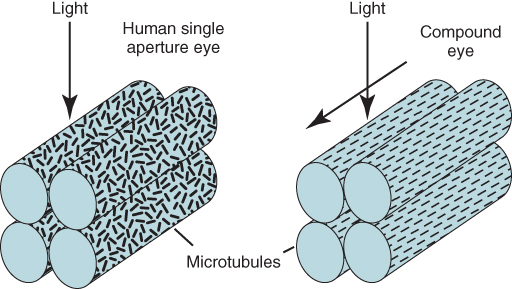
Figure 6.4 Alignment of visual molecules.
The sensitivity to polarization has been shown to be useful in a number of visual functions including increase in contrast, orientation, navigation, prey detection, predator avoidance, and intraspecies signaling. Aquatic animals, such as the cuttlefish, are able to change the light polarization by changing their skin properties; this is used for communication and to distinguish objects under water [20]. Ctenophore plankton is completely transparent in unpolarized light but can be easily detected when placed between cross polarizers. The electric field vector patterns in the sky are used by insects such as ants and bees as a reference for compass information in navigation.
In summary, the compound eyes of insects have properties that are ideally suited for machine vision applications. A vision system can be greatly augmented by adapting different sensor models with different capabilities. The polarization vision of insects has an impact on the image formation and thus significantly affects the image features used for decision making. These polarization features can be used with conventional camera technology for image formation, leading to numerous biologically inspired applications. Polarization vision is already being explored in the fields of robotic orientation and navigation, automatic target detection and recognition, scene segmentation, camouflage breaking and communication, and underwater vision. Light rays get reflected when they strike a reflecting surface, and the reflected light is polarized depending on the incident light and the nature of the reflecting surface. This polarized component can be used to detect the nature of the surface, for example, to discriminate between a metal and a dielectric surface [21, 22].
The application of polarization vision in detecting transparent objects for object recognition and detection is presented in Section 6.2. Flying insects have extraordinary visual capabilities. Their ability to detect fast motion in the visual scene and avoid collision using low-level image processing and little computational power makes their visual processing interesting for real time motion/collision detection in machine vision applications. The ability of the compound eyes to detect fast-moving objects is explored in machine vision applications in Section 6.3.
6.2 Polarization Vision - Object Differentiation/Recognition
In machine vision applications, object differentiation or recognition in the visual scene is very important. To determine the shape of the objects, usually an active or passive light technique is used. Active light techniques include laser range scanning, coded structured light systems, digital holography, or time-of-flight scanners, whereas passive techniques are mainly stereovision, photogrammetry, or shape from techniques such as shading, optical flow, motion, focus, and so on. Active range scanning techniques actively control the light in the scene as compared to passive sensing and thus are more reliable in detecting patterns of light and features of the scene [23].
An important machine vision problem for object recognition is to recognize transparent or specular objects and opaque objects in the visual scene. In applications such as environment monitoring, security surveillance, or autonomous robotic navigation using visual sensors, the recognition of a transparent object such as glass from opaque objects is particularly important. If the transparent objects in the environment are not detected, the autonomous agents would fail in tasks such as manipulation or recognition of objects. A collision, for example, would be inevitable if the robot tried to manipulate a known object but is incapable of recognizing a transparent object located in between.
Transparent objects are common in any environment; they allow seeing the content directly owing to their transparency. The perception of transparent surface is a difficult vision problem due to the absence of body and surface reflections. Further, the multiple reflections inside the transparent objects make them difficult to detect. When a transparent object is present in an environment or scene, the light through the scene is characterized by three basic processes – specular reflection at an object's surface, specular transmission at the surface of a transparent object, and linear propagation within an object's interior and through empty space [24]. The light reflected from a transparent object is mostly specular, while in case of opaque objects, the reflections are mostly diffuse [21, 22]. Specular reflection is the reflection of light from a surface in which light from a single incoming direction is reflected into a single outgoing direction. It obeys the laws of reflection. Diffuse reflection is the reflection of light at many angles rather than a single angle as in the case of specular reflection. It is diffuse reflection that gives color to an object. For normal camera systems, transparent objects are almost invisible except for specularities. This makes their detection and shape estimation difficult.
Despite the prevalence of transparent objects in human environments, the problem of transparent object recognition has received relatively little attention. The available vision algorithms to detect or model transparent surfaces can be classified into two groups. The first group of algorithms tries to enhance the surface-related properties to define the surface's shape. The shape-from-distortion algorithms tries to reconstruct the 3D shape of the transparent surface by analyzing the patterns that are distorted by specular reflection [25–27]. The shape-from-specularity approaches uses the highlights created at points on the surface owing to specular reflection of the incident light for the reconstruction of the surface points [28, 29]. The structure-from-motion algorithms uses the apparent motion of the features in the image plane of a moving camera to reconstruct the transparent surface [30, 31]. The second group of algorithms tries to synthesize a realistic image of transparent objects without using a 3D shape information. These algorithms try to capture multiple-view points to create novel views using interpolation [24]. Many algorithms also determine the surface shape by separating overlapping images of reflected and transmitted images from the transparent surface. The specular stereo algorithm relies on a two-camera configuration or a moving object observer to reconstruct the transparent objects [28, 32].
The appearance-based algorithms for object and category recognition are not appropriate for transparent objects where the appearance changes dramatically, depending on the background and illumination conditions. Detection of transparent objects using the background scene contents is also popular. The method captures a local edge energy distribution characteristic of the refraction using the latent factor model. Machine-learning-based methods, for instance, the additive model of patch formation using latent Dirichlet allocation (LDA) is quite efficient, but it is computationally intensive and results vary with illumination conditions [33]. Other methods based on absorption of particular light wavelengths by transparent objects are computationally less expensive as compared to the former methods, but require sophisticated and expensive equipment such as time-of-flight cameras, LIDAR sensors, and so on [34]. These methods try to use reflection of infrared radiation from transparent objects. The methods are computationally intensive and not suited for real-time applications.
In nature, organisms are often required to differentiate between opaque and transparent objects for their survival. For example, flying insects need to detect transparent objects to avoid collision, while aquatic animals need it for navigation under water. The visual predators need to detect transparent aquatic animals for their survival. The transparent prey uses camouflage in which the animal reflects or produces partially polarized light to reduce the dark area of the body and matches the background illumination, thus making it visually transparent. The polarization sensitivity of the predator's eyes helps in overcoming the radiance matching effects and thus allows predators to detect transparent prey, break camouflage, and increase the detection range of the target. As discussed in Section 6.1, the photoreceptors of in the compound eye of the insects react differentially to partially polarized light [35].
The reflection from a transparent object is mostly specular, while reflection from an opaque object is mostly diffused. Because of specular reflection from transparent objects, the reflected light is linearly polarized, while the light reflected from opaque objects is not polarized. Hence, analysis of light reflected from different objects using a polarizing filter can be used to classify objects into being transparent or opaque. Polarization-based algorithms are often used to describe or enhance surface-related properties of transparent objects. These algorithms are gaining popularity due to their effectiveness and simplicity in detecting and measuring specular or surface reflection. Polarization-based algorithms, however, suffer from surface reflection and ambiguity problems. Further polarization-based analysis is difficult when transmission, rather than specular reflection, dominates image formation [24].
In this section, a bioinspired algorithm using polarization of reflected light to detect transparent objects is presented. The bioinspired algorithm can be used in many applications of machine vision where objects can be classified in real time. This method is computationally inexpensive and only a polarizing filter together with a camera is required.
6.2.1 Polarization of Light
An electromagnetic wave is said to be linearly polarized if the oscillation of its electric and magnetic vectors are confined to specific directions. If the electric and magnetic vectors are not defined in any direction, the electromagnetic wave is said to be unpolarized. Sunlight is considered to be unpolarized by nature. Polarization can also be approximated as intensity in one direction, thus unpolarized light has equal magnitude in all directions. When this light is passed through a polarizing material, specularly reflected from any surface, or scattered by particles (e.g., Rayleigh scattering by air molecules), it gets partially polarized. Figure 6.5 shows the polarization of light by reflection and transmission. The incident ray makes an angle of incidence of ![]() with the plane of incidence
with the plane of incidence ![]() . The incident ray has two polarization components, parallel (
. The incident ray has two polarization components, parallel (![]() ) and perpendicular (
) and perpendicular (![]() ). When the incident ray reaches the boundary, it is divided into a reflected and a refracted (transmitted) wave component. The reflected and transmitted rays also consist of two polarization wave components, parallel (
). When the incident ray reaches the boundary, it is divided into a reflected and a refracted (transmitted) wave component. The reflected and transmitted rays also consist of two polarization wave components, parallel (![]() ,
, ![]() ) and perpendicular (
) and perpendicular (![]() ,
, ![]() ) respectively. The reflected and transmitted light are polarized on the basis of the nature of the surface and the incident angle.
) respectively. The reflected and transmitted light are polarized on the basis of the nature of the surface and the incident angle.
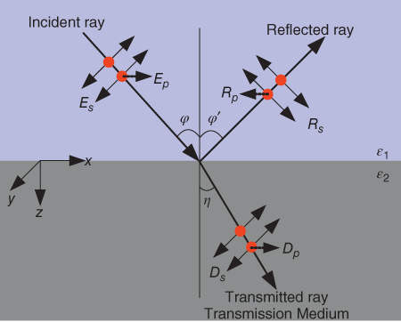
Figure 6.5 Polarization of light by reflection and transmission.
The transmission of polarized light through a linear polarization filter is shown in Figure 6.6. The intensity of the transmitted partially polarized light wave through a linear polarization filter is given by Malus' law. According to Malus' law, when a perfect polarizer is placed in a path of a polarized beam of light, the transmitted intensity, ![]() , through the linear polarizer is given by
, through the linear polarizer is given by
6.2![]()
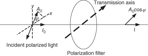
Figure 6.6 Transmission of a polarized beam of light through a linear polarizer.
where ![]() is the incident intensity and
is the incident intensity and ![]() is the angle between the light's initial polarization direction and the transmission axis of the linear polarizer. The intensity of the transmitted partially polarized light can also be expressed as
is the angle between the light's initial polarization direction and the transmission axis of the linear polarizer. The intensity of the transmitted partially polarized light can also be expressed as
6.3![]()
where ![]() and
and ![]() represent the minimum and maximum intensity transmitted through the linear polarization filter as shown in Figure 6.7.
represent the minimum and maximum intensity transmitted through the linear polarization filter as shown in Figure 6.7.
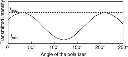
Figure 6.7 Transmitted light intensity.
The values ![]() and
and ![]() are obtained for different angles depending on the type of polarizer used. For a 0° polarizer,
are obtained for different angles depending on the type of polarizer used. For a 0° polarizer, ![]() and
and ![]() would be equal to
would be equal to ![]() and
and ![]() respectively because the horizontally polarized component would pass completely, while the vertical component would be blocked completely. Similarly, for a 90° polarizer,
respectively because the horizontally polarized component would pass completely, while the vertical component would be blocked completely. Similarly, for a 90° polarizer, ![]() and
and ![]() would be equal to
would be equal to ![]() and
and ![]() , respectively. The total intensity of the light and the degree of polarization (the proportion of polarized components in the partially polarized light) can be expressed as
, respectively. The total intensity of the light and the degree of polarization (the proportion of polarized components in the partially polarized light) can be expressed as
6.4![]()
6.5![]()
Partially polarized light is composed of a dominating perfectly polarized component and traces of unpolarized components. The degree of polarization (DOP) measures the degree of the linearly polarized light component in a beam of partially polarized light. If the reflected light is unpolarized, DOP is 0, while if the reflected light is polarized, the DOP is 1. Completely linearly polarized light is observed when the incident angle and the reflecting angle are at the Brewster angle [36]. At the Brewster angle, the light reflected from the surface is completely linearly polarized. The degree of polarization depends on angle of incidence and refractive index of the material. It is given by the equation
6.6![]()
where ![]() is the angle of incidence and n is the refractive index of the material.
is the angle of incidence and n is the refractive index of the material.
The description of the state of polarization of light is provided by Stokes' polarization parameters. Stokes' parameters wereintroduced in 1852 by Sir George Gabriel Stokes. The polarization ellipse is only valid at a given instant of time, a time average (Eq. (6.7)) of the ellipse gives the Stokes' parameters of light.
6.7![]()
where ![]() and
and ![]() are the amplitudes of the light wave and
are the amplitudes of the light wave and ![]() is the phase difference between the
is the phase difference between the ![]() and
and ![]() waves.
waves.
Equation (6.7) can be expressed in terms of the Stokes' parameters ![]() ,
, ![]() ,
, ![]() and
and ![]()
6.8![]()
where
6.9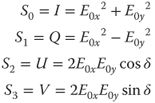
The first Stokes' parameter ![]() represents the total intensity, the parameters
represents the total intensity, the parameters ![]() and
and ![]() represent the linear polarization state, and
represent the linear polarization state, and ![]() , the circular part [37]. The Stokes' parameters allow for determination of the degree of polarization directly from the measured intensity values. The Stokes' degree of polarization is given by equation
, the circular part [37]. The Stokes' parameters allow for determination of the degree of polarization directly from the measured intensity values. The Stokes' degree of polarization is given by equation
6.10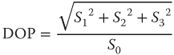
If the light wave is assumed to be linearly polarized, the degree of polarization is often referred to as degree of linear polarization (![]() ) and is expressed as
) and is expressed as
6.11![]()
Besides the degree of polarization and Stokes' degree of polarization, the polarization Fresnel ratio (PFR) is also often used to characterize linear polarized light. The PFR was introduced by Wolff [21] and is found to be a very useful tool to distinguish between the two linearly polarized states, horizontal and vertical, respectively. Using the Fresnel equations, the PFR can be written as
6.12![]()
where ![]() and
and ![]() refer to Fresnel perpendicular and parallel reflection coefficients respectively [21]. The Fresnel coefficients are derived from the Fresnel reflectance model. This model describes the behavior of electromagnetic waves when reflected from a surface. It gives the reflection coefficients parallel and perpendicular to the plane of incidence in terms of refractive index, angle of incidence, reflection, and refraction.
refer to Fresnel perpendicular and parallel reflection coefficients respectively [21]. The Fresnel coefficients are derived from the Fresnel reflectance model. This model describes the behavior of electromagnetic waves when reflected from a surface. It gives the reflection coefficients parallel and perpendicular to the plane of incidence in terms of refractive index, angle of incidence, reflection, and refraction.
PFR can be expressed in terms of maximum and minimum light intensity as is DOP, by using Fresnel reflectance model. The Fresnel reflectance model implies the following two equations [38]:
6.13![]()
6.14![]()
where, ![]() and
and ![]() are same as in Eq. (6.12) and
are same as in Eq. (6.12) and ![]() is the diffuse component of reflection. From Eqs (6.12) and (6.13) [37],
is the diffuse component of reflection. From Eqs (6.12) and (6.13) [37],
6.15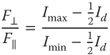
Since, in specular highlight regions, ![]() (
(![]() refers to the specular component of reflected light), Eq. (6.15) could be approximated to [38]
refers to the specular component of reflected light), Eq. (6.15) could be approximated to [38]
6.16![]()
If a polarizer with a transmission axis at 0° is used, then
6.17![]()
6.18![]()
Hence from Eqs. (6.16), (6.17), and (6.18) we have
6.19![]()
From Eqs (6.5), (6.17), and (6.18), degree of polarization can be calculated as
6.20![]()
To calculate the degree of polarization in terms of transmitted intensity using Stokes' parameters, Eq. (6.10) can be further simplified as shown in Eq. (6.21). The Stokes' parameters ![]() in Eq. (6.10) can be neglected for perfectly linear polarized light. The degree of polarization obtained after ignoring
in Eq. (6.10) can be neglected for perfectly linear polarized light. The degree of polarization obtained after ignoring ![]() is called the degree of linear polarization (DOLP).
is called the degree of linear polarization (DOLP).
6.21![]()
The Stokes' parameters in terms of the transmitted intensity and the transmission axis of the linear polarizer can be written as
6.22![]()
6.23![]()
Therefore, from Eqs (6.21), (6.22), and (6.23), Stokes' degree of polarization (p) can be expressed as
6.24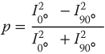
The degree of polarization and the angle of polarization parameters are related to the geometry of the optical element. Thus these parameters help to determine the shape of the transparent objects.
6.2.2 Polarization Imaging
Polarization imaging offers an alternative way of visualizing and distinguishing transparent objects from their environment. Saito et al. presented a method which used partial polarization to highlight surface points [39]. If the light is polarized by reflection, the polarization is minimal in the plane of reflection, that is, in the plane containing the incident light ray, the surface normal, and the viewing ray. Chen et al. [40] uses polarization and phase shifting of light to target surface scanning of transparent objects. Phase shifting enables the separation of specular components from diffuse components [41]. The polarization components of the specular and diffuse components are then used to detect transparent surfaces. Two orthogonally polarized images are used to remove multiple-scattering from the object's surface, thus enabling the recovery of the object's shape.
The detection of shape of single-colored objects is difficult from captured images from a single view. A polarization camera, however, makes it easier to detect differences in the surface orientation of single-colored objects. The polarized state of light from a subject differs depending on the surface orientation of that subject. This is because the unpolarized light upon reflection from the object becomes partially linearly polarized, depending on the surface normal and the refractive index of the medium. These differences can be captured as polarization images with a polarization camera. The constraints on the surface normal can be determined using the Fresnel reflectance model [21]. Figure 6.5 shows the specular reflection of an unpolarized light wave on a surface.
The reflection from a transparent object is mostly specular while reflection from an opaque object is mostly diffused. Because of the specular reflection from transparent objects, the reflected light is partially polarized, while the light reflected from an opaque object is unpolarized. Hence, analysis of light reflected from different objects using a polarizing filter can be used to classify objects into being transparent or opaque. This method of classification can be used in real time in machine vision applications. This method is computationally inexpensive and only a linear polarizing filter together with a camera is required.
In this section, an efficient way to discriminate between transparent and opaque objects using degree of polarization of reflected light is presented. The algorithmworks efficiently when the polarization state of the light reflected from the objects is preserved during image capture and analysis.
6.2.2.1 Detection of Transparent and Opaque Objects
A polarization camera is a generalization of the conventional intensity camera and it allows acquisition of polarization information from an object. The polarization camera consists of a normal intensity camera and a polarization filter. Rotation of the polarization filter in front of the camera allows the polarized information to be recorded. A polarization filter has the property either to transmit light vibrating in one direction producing linearly polarized light or to transmit light with a sense of rotation producing circularly polarized light. Basically, a polarization filter translates polarization information into intensity difference information. This is important as humans are able to perceive intensity information but not polarization information. Thus a polarization sensor has to sense the intensity of light, the polarized component of the incident light, and the angle of the linearly polarized component. State-of-the-art polarization image sensors are based either on a standard CMOS/CCD camera coupled with an external polarization filter controlled externally, or on integrated polarization filters fabricated on top of the pixel array. The latter can measure polarization information in real time and increase the speed of sensing polarization components of the reflected light. Embedded wire grid polarizers on the imaging sensors for real time polarization measurements are described in Refs [6, 42, 43].
Theoretically, transparent objects reflect light specularly. So if a transparent object is observed through a polarization filter and the transmission axis of the filter is rotated, a sinusoidal variation in the intensity of light which is reflected from the transparent object should be observed. The experimental setup to detect reflected polarized light is shown in Figure 6.8 [44]. In the figure, ‘i’ and ‘r’ denote the angle of incidence and angle of reflection, respectively. The light source used was a halogen bulb.
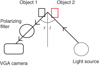
Figure 6.8 Experimental setup.
Objects 1 and 2 in the figure correspond to a transparent and an opaque object respectively. The opaque object was chosen such that the specular reflection component from it was small as compared to its diffuse reflection component. The polarizing filter used was an absorption-based polarizer. Absorption-based polarizers are made of materials whose crystals preferentially absorb light polarized in a specific direction. This makes them good linear polarizers. The camera used was a VGA webcam from Logitech. Owing to the camera sensitivity, noise, and disturbance in the polarization state of light due to air molecules, the polarization phenomenon could not be observed if the objects were farther than 25 cm away from the camera. This maximum distance can be improved if imaging conditions are brighter and the camera is more sensitive to lower light intensities. The light source used was a 12 V halogen bulb. Owing to natural illumination, the polarization state of the light reflected from the objects got distorted. So, to capture the lighting effects on polarized images, the images were taken in the dark with almost zero natural illumination. From Eq. (6.9), it is clear that three images with different polarizer orientations are required to determine the components of the polarization imaging. The three orientations of the polarizer filters are often selected to be 0°, 45°, and 90°.
The light reflected from a transparent object is polarized; therefore, on rotating the transmission axis of the polarizing filter, the intensity of the light reflected from transparent object should vary according to Malus' law. Since the angle of incidence at the measured pixel is small (measurement taken at the specular highlight region), it could be assumed that the intensity is directly proportional to square of the cosine of the angle. Using the experimental setup of Figure 6.8, the variations in intensity on changing the transmission axis of the linear polarizer is shown in the Figure 6.9 [44]. The transmission axis of the polarization filter was varied in steps of 30°.
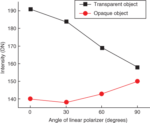
Figure 6.9 Variation of intensity with the angle of the linear polarizer.
The intensity variation plot for the transparent object, as expected, has a negative slope in accordance with Malus' law. For the opaque object, no particular trend was expected. But the intensity plot had a positive slope, indicating that the intensity increased with the angle of the transmission axis of the polarizing filter. However, the intensity variation of the object pixels due to the polarization of light in the case of the opaque object was not much higher as compared to the intensity variation obtained in the case of the transparent object.
As discussed in Section 6.2.1, the DOP is a measure of the polarized component of light. To measure the DOP, it is assumed that the imaged object has uniform surface texture and refractive index throughout. The degree of polarization then depends only on the angle of incidence. The degree of polarization is expected to be a maximum at Brewster's angle. The variations in the degree of polarization with varying angles of incidence are shown in Figure 6.10 [44].
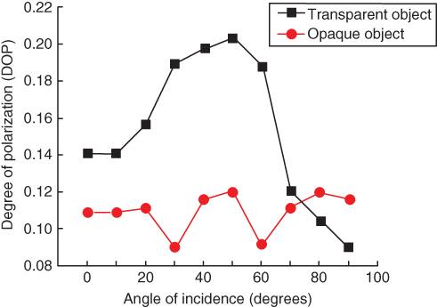
Figure 6.10 Variation in the degree of polarization with angle of incidence.
It can be seen from the figure that as the transmission axis of the linear polarizer is increased, the degree of polarization for the transparent object increases to a maximum value and thereafter decreases. The peak is observed around 50°, which is approximately equal to Brewster's angle for air to glass transition – where the degree of polarization should be theoretically maximum and equal to unity. For opaque objects, the variations observed were random and quite small as compared to that for transparent objects. The magnitude of degree of polarization for opaque objects was always quite lower than that for transparent objects.
The variations in the PFR and Stokes' degree of polarization with varying angles of incidence are shown in Figures 6.11 and 6.12, respectively.
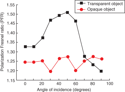
Figure 6.11 Variation of PFR with angle of incidence.
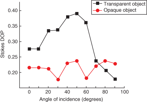
Figure 6.12 Variation of Stoke's degree of polarization with varying angle of incidence.
The profiles for Stokes' degree of polarization and polarization Fresnel ratio (Tables 6.1 and 6.2)were similar to the degree of polarization even though their values were different from each other. This similar trend of increase in the PFR and Stokes' degree of polarization with angle of incidence was observed for transparent objects, while for opaque objects, there was not much variation.
Table 6.1 Degree of polarization
|
Angle of incidence (degrees) |
DOP (transparent object) |
DOP (opaque object) |
|
0 |
0.1464 |
0.08904 |
|
10 |
0.1464 |
0.08904 |
|
20 |
0.1526 |
0.1089 |
|
30 |
0.1911 |
0.08658 |
|
40 |
0.1951 |
0.1093 |
|
50 |
0.1818 |
0.08695 |
|
60 |
0.1549 |
0.0945 |
|
70 |
0.09499 |
0.1015 |
|
80 |
0.08466 |
0.09875 |
|
90 |
0.05780 |
0.05862 |
Table 6.2 Polarization Fresnel ratio
|
Angle of incidence (degrees) |
DOP (transparent object) |
DOP (opaque object) |
|
0 |
1.3430 |
1.1955 |
|
10 |
1.3430 |
1.1955 |
|
20 |
1.3602 |
1.2444 |
|
30 |
1.4725 |
1.1896 |
|
40 |
1.4848 |
1.2454 |
|
50 |
1.4444 |
1.1905 |
|
60 |
1.3666 |
1.2087 |
|
70 |
1.2099 |
1.2259 |
|
80 |
1.1850 |
1.2191 |
|
90 |
1.1227 |
1.1245 |
The polarization state for the diffuse and specular components of the reflection also depend on the reflecting surface, and the measurement of polarization state of the reflected light serves as an indicator for the type of material surface. In metals, the specular component of reflection is greater than the diffuse component of reflection, while in plastics, the diffuse component dominates the specular component of reflection. This varies the degree of polarization of the reflected light, which is shown to be able to differentiate among various reflecting surfaces on the basis of intensity variations [22] (Table 6.3).
Table 6.3 Stokes' degree of polarization
|
Angle of incidence (degrees) |
DOP (transparent object) |
DOP (opaque object) |
|
0 |
0.2866 |
0.1767 |
|
10 |
0.2866 |
0.1767 |
|
20 |
0.3233 |
0.2143 |
|
30 |
0.3687 |
0.1718 |
|
40 |
0.3759 |
0.2159 |
|
50 |
0.352 |
0.1726 |
|
60 |
0.3023 |
0.1873 |
|
70 |
0.1884 |
0.2009 |
|
80 |
0.1683 |
0.1955 |
|
90 |
0.1154 |
0.1168 |
6.2.2.2 Shape Detection Using Polarized Light
The detection of shape of a single-colored objects is difficult from captured images from a single view. A polarization camera, however, makes it easier to detect differences in the surface orientation of single-colored objects. The polarized state of light from a subject differs depending on the surface orientation of that subject. This is because the unpolarized light upon reflection from the object becomes partially linearly polarized, depending on the surface normal and the refractive index of the medium. These differences can be captured as polarization images with a polarization camera. The constraints on the surface normal can be determined using the Fresnel reflectance model [21] as described in Section 6.2. The surface normals are computed using the polarized images and then the 3D surface of the object is obtained by integrating the surface normals [45]. Miyazaki et al. [36] uses two polarization images taken from two different directions: one polarization image is taken before the object is rotated and the other polarization image is taken after rotating the object through a small angle. The degree of polarization of identical points on the object surface is compared between the two images. The correspondence between the two images is then used to estimate the shape of the transparent object.
Polarization of light is also used to recover the surface shape of transparentobjects [36]. The two optically important directions of linear polarization after reflection from the surface are the directions perpendicular and parallel to the surface plane of incidence. After reflection from the surface, the direction of the polarization perpendicular and parallel to the plane of incidence do not change; however the phase and the intensity of the light changes depending on the direction of polarization and the angle of incidence. The degree of polarization of light reflected from the object's surface, depends on the reflection angle which, in turn, depends on the object's surface normal. Thus by measuring the degree of polarization, the surface normal of the object can be calculated. The potential applications of the shape determination of a transparent object includes object recognition for single-colored objects in a production line. The polarization camera also makes it easier to detect the presence of foreign material.
As observed in the previous subsections, the magnitude of degree of polarization (also Stokes' DOP and PFR) is significantly higher for image pixels corresponding to transparent objects as compared to the rest of the image pixels. This has been used to segment the transparent object from the background. Figure 6.13 shows the original image containing a transparent and an opaque object illuminated by a small halogen light source.
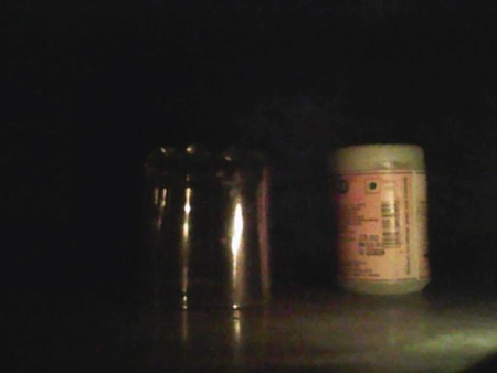
Figure 6.13 Original test image.
DOP values were obtained for every image pixel by taking two images (angle of rotation of polarizer 0° and 90°) and using Eq. (6.20). The matrix containing DOP values was converted into a grayscale image which is shown in Figure 6.14. The image can be converted into a binary image by taking a low threshold value and this image can be analyzed in a similar way thereafter. It can be seen that transparent object pixels are more “white” than the remaining image pixels, including the background and that opaque objects are “black.” Using a suitable threshold and some image-processing operations such as region segmentation, morphological operations (dilation, erosion, closing, and opening), and edge detection, the approximate shape of the object could be determined even in a dark imaging environment as shown in Figure 6.15.
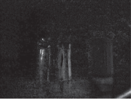
Figure 6.14 Image formed by degree of polarization matrix.
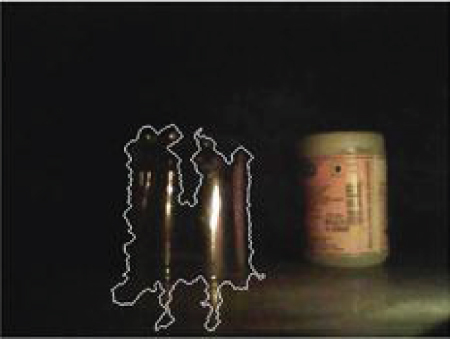
Figure 6.15 Classified transparent object after applying image-processing functions on the polarization matrix image.
The method can be used to determine the shape of transparent objects. Since measures of polarization are easy to calculate and need less equipment, this is a computationally inexpensive and economical method. To guide autonomous agents, a system to capture images at required angles of rotation is desirable. A motorized polarizer should be installed in front of the camera. For taking images at a specific angle of rotation, a control circuit for synchronizing the camera and the polarizer is also required. Images acquired by this system should then be analyzed by the processor responsible for image-processing operations for the agent. With minor operations, the location and shape of the transparent object can be detected. The processor can thus control the navigation of the autonomous agent appropriately.
6.3 High-Speed Motion Detection
As discussed in Section 6.1.1, flying insects are able to detect fast motion in the visual scene and avoid collision using low-level image processing and little computational power. This makes their visual processing interesting for real-time motion/collision detection in machine vision applications. Real-time detection of targets with minimal energy consumption for surveillance using wireless sensor nodes is becoming popular. The sensor nodes consist of multiple autonomous functional units that cooperatively monitor the desired property.
A camera as a sensor node in the wireless sensor network would be desirable as it can be used in many applications such as surveillance, environment monitoring, smart homes, virtual reality, and medicine. As charge coupled devices (CCDs) and complementary metal oxide semiconductor (CMOS) images/video cameras become smaller, less expensive, and more power efficient, the cameras in wireless sensor nodes will become more powerful and widespread in use. The CMOS image sensor is more suited for application in the wireless sensor node to CCD owing to its low power operation and possibility of incorporating processing power within the pixel. The in-pixel processing of sensed information helps in reduction of the signal information being sent out and thus reduces the amount of data transmitted over sensor nodes. A wireless sensor node with an integrated image sensor would have the following requirements: (i) low power consumption (in microwatts), (ii) high dynamic range (![]() 100 dB), (iii) digital interface with few or no extra components, (iv) data compression at sensor level, (v) low cost, and (vi) fast readout.
100 dB), (iii) digital interface with few or no extra components, (iv) data compression at sensor level, (v) low cost, and (vi) fast readout.
The power consumption of the vision sensors used in wireless sensor nodes should be minimal. Therefore, computationally intensive vision algorithms cannot be used as they are typically power hungry. Conventional vision sensors such as CMOS or CCD image sensors are not suitable for wireless nodeapplications as they sample the visual field at tens to thousands of times per second, generating kilobytes or megabytes of data for each frame. The resulting information must be heavily processed to derive any result, resulting in complex systems and increased power consumption. Furthermore, these vision sensors are not suitable for all visual environments as most of the available vision sensors cannot handle low-contrast environments. The dynamic range of the available vision sensors is limited and thus cannot image the entire available light range. The dynamic range of a sensor expresses the ability to capture dark as well as bright sections within an image while maintaining the highest fidelity. The readout speed of the vision sensors in wireless sensor nodes also needs to be very high to be able to detect any changes in the visual scene. For fast readout of images, high-speed readout circuits are needed, which are power hungry. Further, as processing algorithms become more and more demanding, processing capabilities reach a bottleneck in realizing efficient vision sensor nodes.
Most of the available vision sensors are modeled on the basis of the single-aperture human eye. As discussed in Section 6.1.1, the compound eye is one of the most compact vision systems found in nature. This visual system allows an insect to fly with a limited intelligence and brain-processing power. In comparison to single-aperture eyes, compound eyes have a much wider field of view (FOV), better capability to detect moving objects, higher sensitivity to light intensity, but much lower spatial resolution. Thus this type of vision system is ideal for wireless sensor nodes. A vision sensor for wireless sensor networks that performs local image capture and analysis has been presented [46]. The vision sensor was shown to be useful in object detection and gesture recognition. The wireless sensor node proposed by Kim et al. [47] was operated in rolling-shutter mode. In rolling-shutter mode, imaging a moving object introduces motion artifacts. The power consumption of 1 mW by the image sensor was also on a higher side with the output buffer alone consuming about 72% of the power [47].
In this section, some bioinspired properties that can be implemented in a wireless sensor node are discussed. Motion detection using temporal differentiation is used. The temporal differentiation in binary domain replicates the “flickering effect” of the insect eye when the object is in motion. The binary motion detection can be very fast and energy efficient because of considerable reduction in the output bandwidth of information.
6.3.1 Temporal Differentiation
Temporal differentiation helps to attain high dynamic range, data compression at the sensor level, and fast readout. The active differential imaging process involves getting the image of a scene at two different instances of time and subtracting the two frames as shown in Figure 6.16(a). The two images are separately captured and stored in the memory. The subtraction of the two images can either be done in analog or digital domain. In temporal differentiation, the stationary objects with constant illumination will be erased by the imaging system. If there is a motion between the two frames, then the motion information will be recorded. This serves in imaging high light environments. These algorithms are widely used in industrial and scientific fields for motion detection, object tracking, or recognition and so on.
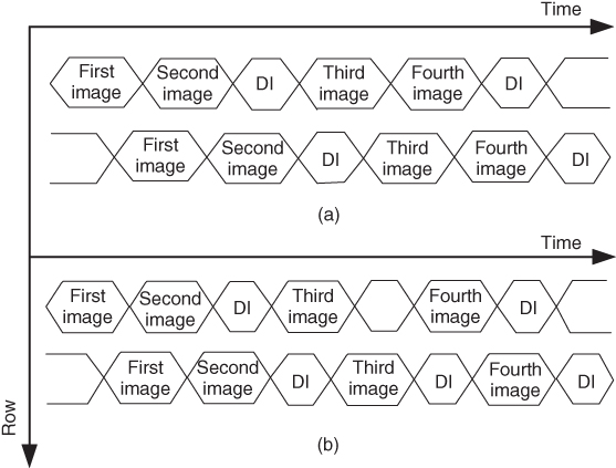
Figure 6.16 Temporal differentiation schemes (DI – difference image). (a) Differential imaging and (b) visual tracking or saccadic imaging.
A variant of temporal differentiation is the visual tracking mode or saccadic imaging used by insects as shown in Figure 6.16(b). Here the background information is stored and the current image frame is subtracted from the background image to determine change in state or motion in the visual field. These processes are very apt for fast tracking. In this model, the background information is always maintained. The temporal difference image enhances the background subtraction capability and thus is very useful in motion detection. Some of the applications of this invariance to ambivalent light are human face recognition, pseudo 3D sensing, and so on.
The use of digital subtractor would need a fast readout circuit together with a frame buffer. These systems are highly complex and they consume a lot of power. A differential image sensor with high common mode rejection ratio (CMRR) was proposed by Innocent and Meynants [48], where both the images are stored in the analog domain and a difference signal is obtained during readout. Common-mode rejection ratio of a device is the measure of the tendency of the device to reject a common input signal. A high CMRR is desired for applications where the signal of interest is a small voltage fluctuation superimposed on a large voltage offset or when the required information is contained in the voltage difference of two signals.
A high-CMRR differential CMOS imager sensor, capable of producing both analog and digital differential images using two in-pixel analog and digital memories has been designed. The details of the CMOS image sensor are presented elsewhere [6]. The subtraction is done pixel by pixel and the analog image signal is transferred to an external 12-bit ADC, to get the digital pixel data. The process is repeated for each image line and thus a differential image is obtained without the requirement for an off-chip computation [6]. Pixel-level processing helps in decreasing the data rate from the sensor, compared to frame-level processing. This often results in compact, high-speed, and low-power solutions. Focal plane computations are also free from temporal aliasing, which is usually a problem in motion detection algorithms.
However, processing analog/digital information takes computational power and resources. The compound eyes of the insects are known to process motion information in binary format aided by the “flickering effect” in the eyes when the object moves from one eye unit to another. Figure 6.17 shows the horizontal motion detection using binary optical flow information. Two consecutive frames of a light source moving over the image sensor are shown in Figure 6.17. The first image shows the light source at its initial position and the second image shows it after a slight movement. The two images look very similar, as only a very small motion was introduced. The histograms of the two images are also shown in Figure 6.17. The subtraction of the two images results in a difference image, and the histogram of the pixels which changed states are shown at the bottom of the figure. By selecting a proper threshold, accurate detection of motion can be done [49, 50]. This can detect motion very fast and also as only binary information are produced; pixel-level computations are simple and can be easily implemented. The power consumption of the system will also be very low. Thus such algorithms are best for being adopted in the visual sensor node.
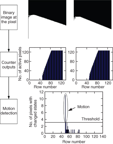
Figure 6.17 Horizontal motion detection using spatially integrated binary optical flow.
Temporal differentiation can also be used to enhance the dynamic range of the system. It is also used to compress pixel information as shown in Figure 6.18. Figure 6.18(a) and (b) shows temporal differential images and Figure 6.18(c) and (d) shows histogram equalization (HE) of the temporal images. Figure 6.18(a) is brighter than (b) as the integration time difference between the temporal samples is larger. 6.18(b) has fewer pixels near saturation, thus able to image higher illuminations, increasing the dynamic range. After HE, the two images have near equal distribution of the contrast. This can be used as an on-chip image compression tool where only the brighter pixels can be scanned for readout, thus increasing the readout speed. This will increase the output bandwidth and also help with power consumption as not all the pixels will be read.
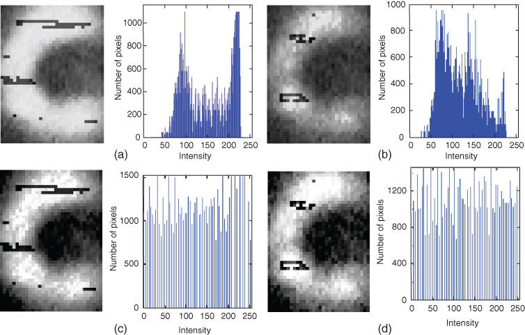
Figure 6.18 Histogram equalization using temporal differentiation. (a) and (b) Temporal images with the first frame captured at 10 ms and the second frame 20 ms, respectively; (c) and (d) Histogram equalization of the temporal images.
6.4 Conclusion
In this chapter, algorithms inspired by the compound eyes of insects are presented, that could be modeled to enhance the visual perception of standard camera systems. Separation of transparent and opaque objects in a visual scene is important in many machine vision applications. The incident light on a surface is reflected and this reflected light is found to be polarized. The polarization of the reflected light depends on the surface properties of the object. Using DOP, PFR, and Stokes' degree of linear polarization, transparent and opaque objects can be identified in a visual scene with relative ease. For most incident angles, the DOP values for transparent objects are quite higher when compared tothose for opaque objects. These measurements could be used to differentiate among transparent and opaque objects by using an appropriate threshold in real time. Further, the polarization matrix can also be used to recover the shape of the transparent object as well. This method is computationally inexpensive and relatively easy to implement in real-time vision systems. The polarization sensing ability in the CMOS image sensor for object differentiation can be useful for many applications such as environment monitoring and surveillance.
Algorithms inspired by the compound eyes of insects for high-speed motion detection for the visual sensor nodes in wireless networks are also presented. A CMOS image sensor operating in temporal differential mode which spatially integrates 1D binary information can be very useful for fast motion detection. The binary information can be generated in-pixel, thus reducing the computational overload making them low-power systems. Temporal differentiation can also be used to compress information.
References
1. 1. Visual perception, http://en.wikipedia.org/wiki/Visual_perception (accessed 4 May 2015).
2. 2. Sabra, A.I. (1989) The Optics of Ibn al-Haytham, Warburg Institute, London, ISBN: 0854810722.
3. 3. Sabra, A.I. (2003) Ibn al-Haytham, brief life of an Arab mathematician: died circa 1040. Harvard Magazine, pp. 54–55.
4. 4. Sabra, A.I. (1966) Ibn al-Haytham's criticisms of Ptolemy's Optics. J. Hist. Philol., 4, 145–149.
5. 5. Nilsson, D.E. (2009) The evolution of eyes and visually guided behaviour. Philos. Trans. R. Soc. London, Ser. B: Biol. Sci., 364 (1531), 2833–2847.
6. 6. Sarkar, M. (2011) A biologically inspired CMOS image sensor. PhD dissertation, ISBN: 978909025980-2.
7. 7. Rieke, F. and Baylor, D.A. (1993) Single-photon detection by rod cells of the retina. Rev. Mod. Phys., 70 (3), 1027.
8. 8. Land, M.F. and Fernald, R.D. (1992) The evolution of eyes. Annu. Rev. Neurosci., 15, 1–29.
9. 9. http://watchingtheworldwakeup.blogspot.ae/2009/11/amazing-housefly-part-2-coolest-eye.html.
10.10. Land, M.F. and Nilsson, D.E. (2012) Animal Eyes, 2nd edn, Oxford University Press, Oxford, ISBN: 978-0199581146.
11.11. Nagata, T., Koyanagi, M., Tsukamoto, H., Saeki, S., Isono, K., Shichida, Y., Tokunaga, F., kinoshita, M., Arikawa, K., and Terakita, A. (2012) Depth perception from image defocus in a jumping spider. Science, 335 (6067), 469–4071.
12.12. Srinivasan, M.V., Zhang, S.W., Chahl, J.S., Barth, E., and Venkatesh, S. (2000) How honeybees make grazing landings on flat surfaces. Biol. Cybern., 83, 171–183.
13.13. Srinivasan, M.V. (1992) Distance perception in insects. Curr. Dir. Psychol., 1 (1), 22–26.
14.14. Goldsmith, T.H. (2006) What birds see. Sci. Am., 295, 68–75.
15.15. Franceschini, N. (1985) Early processing of colour and motion in a mosaic visual system. Neurosci. Res., (Suppl. 2), S17–S49.
16.16. Hardie, R.C. (1986) The photoreceptor array of the dipteran retina. Trends Neurosci., 9, 419–423.
17.17. Nachtigall, W. and Wilson, D.M. (1967) Neuro-muscular control of dipteran flight. J. Exp. Biol., 47, 77–97.
18.18. Heide, G. (1983) Neural mechanisms of flight control in Diptera, in Biona-Report 2 (ed. W. Nachtigall), pp. 35–52.
19.19. Reichardt, W. (1987) Evaluation of optical motion information by movement detectors. J. Comp. Physiol. A, 161 (4), 533–547.
20.20. Mäthger, L.M., Shashar, N., and Hanlon, R.T. (2009) Do cephalopods communicate using polarized light reflections from their skin? J. Exp. Biol., 212 (14), 2133–2140.
21.21. Wolff, L.B. (1990) Polarization-based material classification from specular reflection. IEEE Trans. Pattern Anal. Mach. Intell., 12 (11), 1059–1071.
22.22. Sarkar, M., San Segundo Bello, D., Van Hoof, C., and Theuwissen, A. (2011) Integrated polarization analyzing CMOS image sensor for material classification. IEEE Sens. J., 11 (8), 1692–1703.
23.23. Ihrke, I., Kutulakos, K.N., Lensch, H.P.A., Magnor, M., and Heidrich, W. (2010) Transparent and specular object reconstruction. Comput. Graph. Forum, 29 (8), 2400–2426.
24.24. Kutulakos, K.N. and Steger, E. (2005) A theory of refractive and specular 3D shape by Light-Path Triangulation. IEEE ICCV, pp. 1448–1455.
25.25. Schultz, H. (1994) Retrieving shape information from multiple images of a specular surface. IEEE Trans. Pattern Anal. Mach. Intell., 16 (2), 195–201.
26.26. Halstead, M.A., Barsky, B.A., Klein, S.A., and Mandell, R.B. (1996) Reconstructing curved surfaces from specular reflection patterns using spline surface fitting of normals. Proceedings of ACM SIGGRAPH, pp. 335–342.
27.27. Bonfort, T. and Sturm, P. (2003) Voxel carving for specular surfaces. Proceedings of IEEE International Conference on Computer Vision (ICCV), pp. 591–596.
28.28. Blake, A. and Brelstaff, G. (1988) Geometry from specularity. Proceedings of IEEE International Conference on Computer Vision (ICCV), pp. 297–302.
29.29. Blake, A. (1985) Specular stereo. Proceedings of International Joint Conference on Artificial Intelligence (IJCAI), pp. 973–976.
30.30. Oren, M. and Nayar, S.K. (1996) A theory of specular surface geometry. Int. J. Comput. Vision, 24 (2), 105–124.
31.31. Hartley, R. and Zisserman, A. (2000) Multiple View Geometry, Cambridge University Press, Cambridge.
32.32. Nayar, S.K., Sanderson, A.C., and Simon, D. (1990) Specular surface inspection using structured highlight and Gaussian images. IEEE Trans. Rob. Autom., 6 (2), 208–218.
33.33. Fritz, M., Black, M., Bradski, G., Karayev, S., and Darrell, T. (2009) An additive latent feature model for transparent object recognition. Neural Information Processing Systems.
34.34. Klank, U., Carton, D., and Beetz, M. (2011) Transparent object detection and reconstruction on a mobile platform. IEEE International Conference on Robotics and Automation, p. 5971.
35.35. Nilsson, D.E. and Warrant, E. (1999) Visual discrimination: seeing the third quality of light. Curr. Biol., 9, R535–R537.
36.36. Miyazaki, D., Kagesawa, M., and Ikeuchi, K. (2004) Transparent surface modeling from a pair of polarization images. IEEE Trans. Pattern Anal. Mach. Intell., 26 (1), 73–82.
37.37. Ferraton, M., Stolz, C., and Meriaudeau, F. (2008) Surface reconstruction of transparent objects by polarization imaging. IEEE International Conference on Signal Image Technology and Internet based Systems, pp. 474–479.
38.38. Al-Qasimi, A., Korotkova, O., James, D., and Wolf, E. (2007) Definitions of the degree of polarization of a light beam. Opt. Lett., 32, 1015–1016.
39.39. Saito, M., Sato, Y., Ikeuchi, K., and Kashiwagi, H. (1999) Measurement of surface orientations of transparent objects using polarization in highlight. Proceedings of IEEE Conference on Computer Vision and Pattern Recognition (CVPR), vol. 1, pp. 381–386.
40.40. Chen, T., Lensch, H.P.A., Fichs, C., and Seidel, H.P. (2007) Polarization and phase-shifting for 3d scanning of translucent objects. Proceedings of IEEE Computer Society Conference on Computer Vision and Pattern Recognition (CVPR), pp. 1–8.
41.41. Nayar, S.K., Krishnan, G., Grossberg, M.D., and Raskar, R. (2006) Fast separation of direct and global components of a scene using high frequency illumination. Proceedings of ACM SIGGRAPH, pp. 935–944.
42.42. Tokuda, T., Yamada, H., Sasagawa, K., and Ohta, J. (2009) Polarization-analyzing CMOS image sensor with monolithically embedded polarizer for microchemistry systems. IEEE Trans. Biomed. Circuits Syst., 3 (5), 259–266.
43.43. Sarkar, M., San Segundo Bello, D., Van Hoof, C., and Theuwissen, A. (2010) Integrated polarization-analyzing CMOS image sensor. Proceedings of IEEE International Symposium on In Circuits and Systems (ISCAS), pp. 621–624.
44.44. Mahendru, A. and Sarkar, M. (2012) Bio-inspired object classification using polarization imaging. International Conference on Sensing Technology (ICST), pp. 207–212.
45.45. Morel, O., Meriaudeau, F., Stolz, C., and Gorria, P. (2005) Polarization imaging applied to 3D reconstruction of specular metallic surfaces. Electronic Imaging, International Society for Optics and Photonics, pp. 178–186.
46.46. Rahimi, M., Baer, R., and Iroezi, O.I. (2005) Cyclops: in situ imagesensing and interpretation in wireless sensor networks. Proceedings of the 3rd International Conference on Embedded Networked Sensor Systems.
47.47. Kim, D., Fu, Z., Park, J.H., and Culurciello, E. (2009) A 1-mW temporal difference AER sensor for wireless sensor networks. IEEE Trans. Electron. Devices, 56 (11), 2586–2593.
48.48. Innocent, M. and Meynants, G. (2005) Differential image sensor with high common mode rejection. Proceedings of European Solid-Sate Circuits Conference, pp. 483–486.
49.49. Sarkar, M., San Segundo, D., Van Hoof, C., and Theuwissen, A.J.P. (2011) A biologically inspired CMOS image sensor for polarization and fast motion detection. Proceedings IEEE Sensors Conference, pp. 825–828.
50.50. Sarkar, M., San Segundo, D., Van Hoof, C., and Theuwissen, A.J.P. (2013) Biologically inspired CMOS image sensor for fast Motion and polarization detection. IEEE Sens. J., 13 (3), 1065–1073.
All materials on the site are licensed Creative Commons Attribution-Sharealike 3.0 Unported CC BY-SA 3.0 & GNU Free Documentation License (GFDL)
If you are the copyright holder of any material contained on our site and intend to remove it, please contact our site administrator for approval.
© 2016-2026 All site design rights belong to S.Y.A.