VMware vSphere Design Essentials (2015)
Chapter 3. Designing VMware vSphere Networking
VMware vSphere is a promising virtualization product. Though we may have the desire to begin deployment straightaway, heed the motto of the VMware vSphere network design before you start. We must look at several prerequisites even before we install the VMware vSphere product on our VT-enabled hardware; failing to meet any one of these prerequisites could entail a lot of troubleshooting. Also, another complexity during unplanned deployment is that you will end up with a greater risk of outage on other servers and systems as well. Communication with shared storage, and networks without the requisite preparation may involuntarily take down other servers and systems or in the worst case, this action could cause irretrievable data loss. If you are planning to operate with VMware ESXi in the very first attempt, take the required amount of time. Pay attention to the planning phase; in return, this will save time in the long run. Reading this book will not only ensure that you avoid hours of troubleshooting, but it will also cover core knowledge gained from best practices, derived from numerous lessons learned from previous deployments across different industries. In this chapter, you will learn the essentials of vSphere networking, getting started with vSphere, setting the properties of vSphere, and so on.
This chapter provides an overview of your vSphere networking and design essentials. Looking at our system from a high level, we can see where vSphere network virtualization best fits into the environment. Before you begin with your mission, let's quickly explore the basic definitions that are used in networking circles; they are seen in the following table:
|
Term |
Description |
|
Switch |
This is a hardware networking device that aids as a controller and enables devices, such as computers, printers, servers, and so on, to communicate with each other. |
|
Router |
This is a hardware networking device that helps to direct (route, which is the reason for the name) data/information from one network (LAN) to another (LAN). |
|
Bridge |
This networking device helps to connect to two or more different networks. It is similar to a router, but it analyzes whether the data is being forwarded. |
|
NIC |
This stands for Network Interface Controller (NIC). It is a networking device that helps to connect one system to another over the network. |
|
NIC Teaming |
A collection of multiple uplink adapters are connected to each other to form a team in a single switch. A team can either section the burden of traffic between the virtual networks and physical network or deal passive failovers in the event of a network outage, hardware failure, power failure, or DC outage. |
|
VPN |
This stands for Virtual Private Network (VPN), a private communication network that is usually used within a private company to communicate from a public network. |
|
Packet switching |
This swaps data throughout the Internet. Most data is reduced to smaller packets before the transfer and then reunited at the destination. |
|
VLAN |
This stands for Virtual Local Area Network. It is a broadcast domain created by a switch. |
|
Physical network |
This network enables physical machines with their regions to communicate with each other. It also enables the flow of data. VMware ESXi runs on a physical machine. |
|
Physical Ethernet switch |
Physical adapter or uplink controls the network traffic across systems over the physical network. A switch contains several ports, each of which can be associated with its own physical system or another switch over the network. |
|
Virtual network |
On this network, VMs running on a host are interconnected sensibly to each other in order to send and receive data from other VMs. |
|
Virtual adapter |
This is a network that enables VMs to communicate with each other. Based on this connection, communication in terms of data flows between VMs and physical machines. |
In this chapter, we will cover the following topics:
· VMware vSphere networking essentials
· Designing VMware vSphere Standard (VSS) and VMware Distributed Switches (VDS)
· Determining factors that influence the virtual network
· Designing the VMware vSphere network
· Design considerations for networking layers with industry inputs
VMware vSphere networking essentials
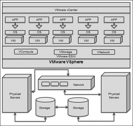
VMware vSphere is the largest and most powerful server virtualization suite used across the globe. It is a stepping stone to software-defined datacenters that use the VMware vCD or your own defined cloud-based datacenter. The VMware vSphere suite provides the flexibility and reliability to compute resources by merging available resources and converting them into an aggregated pool of resources. It has a proven record of high availability, scalability (on demand), fault tolerance, and security. The VMware vSphere suite seamlessly provides vCompute, vStorage, and the vNetwork virtualization layer for aggregated physical resources to operate across datacenters. The following diagram illustrates this flexibility across datacenters:
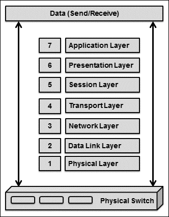
The VMware vSphere virtual switch works in a manner similar to the network layer 2 physical switch. Before we begin with the virtual switch network, let's first look at the networking Open Systems Interconnection (OSI) model, which is the very basic model of the networking world. A computer network is a collection of two or more systems linked together with the main objective of data or information sharing. ISO, along with the IEC-defined standard model for networking, which is called OSI, consists of seven layers as illustrated here:
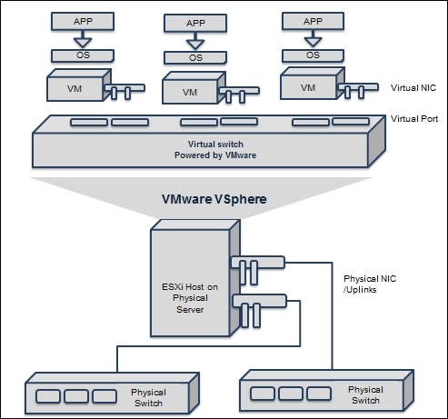
Now, let's explore how to connect the network with VMware vSphere. The vSphere virtual switch is a software layer that allows VMs to communicate with one another. This virtual switch can communicate intelligently with data flows on the network by examining data packets before sending them. The complete communication flow is illustrated here:
The design of VMware VSS and VDS
The VMware vSphere virtual switch is classified into two features, VMware VSS and VMware VDS.
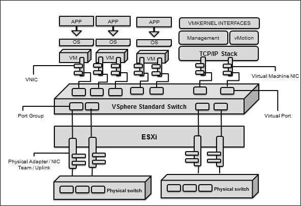
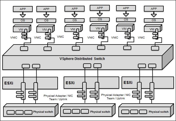
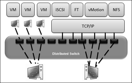
Using the VMware VSS is like using a physical switch; each VMware vSphere ESXi host has its personal virtual switches. It automatically detects where the VM is connected and forwards the packet accordingly. The vSphere Distributed Switch is one virtual switch that is shared across multiple ESXi hosts and acts as a single switch across the associated ESXi host:
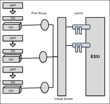
On the virtual switch, the left-hand side shows port groups linked to it; they are connected to VMs. On the left-hand side are uplink connecters that are linked to physical Ethernet adapters on the associated ESXi host. A VM communicates with the physical environment via physical Ethernet adapters that are plugged into the virtual switch adapter. Virtual switches in ESXi are built and operated in the VMkernel. Virtual switches are also called vSwitches.
Note
We cannot telnet in a vSwitch. There is no command-line interface for a vSwitch, apart from the VMware vSphere CLI. Here is an example:
vicfg-vswitch
In spite of these similarities, VMware switches have more variations compared to physical switches. The VMware vSwitch does not use dynamic negotiations for the creation of 802.1q trunks, Port Aggregation Protocol (PAgP), or port channels such as Dynamic Trunking Protocol (DTP). In any case, vSwitch cannot be linked to another vSwitch, thus eradicating a possible loop configuration. vSwitches do not run Spanning Tree Protocol (STP) since looping is a well-known network problem.
Now, let's go ahead and talk about vSphere switches. There are a few things that you need to know: VSSes are created per host. They are unique for each host because they are created on each one. The name of the port group should be unique because this will be validated for the purpose of working with vMotion:
The standard switch is generally used to establish a communication between the physical host (ESXi) and VMs. A VSS can fulfill the gap of circulation internally between the VMs in the identical VLAN, and it aids communication with external networks as well.
In order to set up communication between the physical host (ESXi) and the VM running on the same ESXi, we have to connect a physical NIC in the ESXi to the physical uplink ports on the VSS. VMs have virtual NICs that we connect to port groups on the same standard switch. Wherever the uplinks are connected to each port group, they can utilize one or more physical NICs to allow VM network traffic and network load balancing. If we are already notice that on the vSphere Client console a port group does not have a physical NIC associated to it, the VM on the identical port group can connect with the other VM within the ESXi, but not outside its reach.
A VSS models an Ethernet switch. By default, the number of logical ports for VSS is 120. We are allowed to attach one NIC of a VM to each of its port. Each uplink adapter linked with a VSS utilizes one port. Every logical port on the VSS is a single port group of some sort.
While two or more VMs are associated with the identical VSS, any network circulation between them functions within ESXi. If a physical adapter is associated with the VSS, each VM can use the external network when it is associated with the adapter.
VSS port groups are groups of numerous ports that are in a mutual configuration with each other and bring a stable point for the VM that joins considered networks.
A VMware vNetwork Distributed Switch has a configuration similar to vSwitch from the ESXi host level, and it helps to set up a cumulative unified datacenter level. VMware VDS can be easily administered through VMware vSphere clients who are mandatorily committed to the vCenter Server. As vSwitch comprises VDS port groups that are constructed in a manner similar to port groups on VSS, VDS port groups extend across compound ESXi hosts. This streamlines the configuration of VMs across compound ESXi hosts and enables an easy build that VMware vMotion is capable of. VDS port groups maintain the network port state centrally as VMs, either for planned or unplanned migration from one ESXi host to another using VMware vMotion. This empowers reliable indicators to monitor VMs against exposure to intrusion.
The following diagram illustrates the high-level configuration of the VDS. The VMware VDS abstracts the configuration of vSwitch from the host level to a collective centralized datacenter level. The VMware vNetwork Distributed Switch is managed through VMware vSphere clients that are committed to VMware vCenter Server:
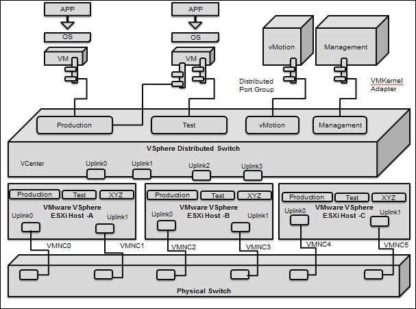
This section will explain not only the architecture of vSphere Distributed Switch, but also its core components, networking configurations, along with the management of ESXi hosts that are connected to the switch that is centralized on the vCenter system. Every host is connected to a host proxy switch that contains the networking settings for the ESXi host that are configured on VMware vSphere Distributed Switch. The VMware VDS contains a minimum of one or a maximum of 5000 VDS port groups. The main reason behind using VDS port groups is to fulfill networking communication between VMs and also to make space for the VMkernel traffic. We have to assess this in order to find each and every VDS port group via its network name (also called a network label). During the process of assigning a name, we must ensure that we provide a unique network label or network name. A record of every VDS port group that we create via the vCenter server is created on each ESXi host that is related to VDS. We need to create a rule for a VDS port group; this rule will be consistent for all hosts in the Distributed Switch. Now, let's explore the architecture shown in the following diagram:
From a functional standpoint, VDS offers a unified control through which we can install, configure, monitor, and administer VM networks for our enterprise datacenter. Apart from these, the other major functionalities are as follows:
· Straightforward alignment of VM networks
· Boosted network monitoring and troubleshooting
· Modern, advanced networking features
Let's explore the listed benefits one by one in the upcoming sections. In VDS, the straightforward alignment of VM networks aids the following choices:
· The VMware VDS key aligns the administration, provisioning, configuration, management, and monitoring of virtual networks across each ESXi host on the datacenter
· The VMware vSphere's distributed switch assists an administrator with control over the following:
o VDS port group naming
o VDS port configurations
o VDS screen settings
o Link Aggregation Control Protocol (LACP)
Note
What is LACP?
LACP is a component that aids transfers and automatically arranges link aggregation among vSphere hosts and the physical switch access layer.
On VDS, there are boosted network monitoring and troubleshooting functionalities. The VMware VDS is key in aligning administration with respect to monitoring and troubleshooting proficiencies. VDS aids the administrator with the monitoring and troubleshooting of the following features:
· RSPAN, ERSPAN, SNMP v3, and IPFIX NetFlow v10
· A network health check is performed to validate whether vSphere has compunction with physical network configurations
· Troubleshooting rollbacks, updates, and recoveries over various phases of administration
· Troubleshooting backup and restore operations on VMs with template configurations over various phases of administration
· Troubleshooting netdumps (network-based core dumps used to debug hosts without even the need for local storage) over various phases of administration
Here are the advanced networking features that aid the following choices:
· VDS offers support for advanced networking features, such as traffic management and bidirectional VM rate limiting, along with modern and advanced networking-management features. These features are listed as follows:
o VDS offers administrator support for core components, such as NetIOC, SR-IOV, and BPBU screening, which are explained here:
Note
What is NetIOC?
VMware vSphere VDS Network Input Output Control (NetIOC) is used to configure instructions and guidelines at the VM level and ensure that the input and output resources are continuously offered for our business-critical applications. NetIOC monitors the network. Whenever it sees jamming or blocking, it spontaneously shifts assets to our highest-priority applications, as demarcated by our business rules.
What is SR-IOV?
VMware vSphere VDS Single Root I/O Virtualization (SR-IOV) is an arrangement that allows a PCIe (PCI Express is a high-speed serial bus that functions more like a network compared to bus) device to appear to be many separate physical PCIe devices.
What is BPBU?
VMware vSphere VDS Bridge Protocol Data Units (BPDU) data contains frame information regarding the switch ID, starting switch port, switch port priority, MAC address, and switch port cost.
o VDS offers administrator support for third-party vSwitch lean-tos, such as IBM 5000V and Cisco Nexus 1000V
Let's now go ahead and explore the terminology used in VDS. A detailed classification of these is given in the following table:
|
Terms |
Description |
|
DV port groups (VDS virtual port groups) |
They specify the port configuration choices for every member port within the virtual switch |
|
Distributed Virtual Uplinks (dvUplinks) |
They provide a smooth layer for physical NICs on every ESXi host across datacenters |
|
Private Virtual Local Area Networks (PVLANs) |
They aid wider compatibility with the available networking infrastructure |
|
Network vMotion |
This streamlines the checking and fixing of problems by tracking the networking status of each and every VM as it moves from one ESXi host to another on a VDS |
|
Bidirectional traffic shaping |
This applies the traffic-shaping rule on the VDS port group and is defined by the average bandwidth, burst size, and peak bandwidth |
|
Third-party virtual switch support |
This offers a stretch for the integration of third-party data planes, control planes, and user interfaces, with the IBM 5000V and Cisco Nexus 1000V |
We will discuss the key enhancements you can find in VMware VSphere 5.5 now. Network health can be monitored, and a report on it can be viewed. The VDS configuration can be backed up and restored on demand. The management network recovery option can be used in the event of a failure. The rollback option has been provided for maintenance periods. Additionally, scalability enhancements have been made. Apart from these, features, such as LCAP, BPDU, and SR-IOV (as you learned in the previous section) are also considered as key additions in VMware VSphere 5.5.
Now, let's go ahead and look at a comparison between VSS and VDS. The following table compares the features of VMware VDS against those of VMware VSS. While VSS is available by default in all editions of VMware vSphere, VDS is only available in the VMware vSphere Enterprise Plus edition. Moreover, VMware vCenter is mandatory for VDS administration; however, this is not the case for VSS. We can manage VSS via the vSphere Client. The following table compares the features of VSS and VDS:
|
Features |
VSS |
VDS |
|
Switching features |
||
|
Support for Layer 2 Forwarding |
Available |
Available |
|
Support for IEEE 802.1Q VLAN tagging |
Available |
Available |
|
Support for Multicast support |
Available |
Available |
|
Support for vMotion Network Policy |
NA |
Available |
|
Physical switch features |
||
|
Support for EtherChannel |
Available |
Available |
|
Support for load-balancing algorithms on the virtual port ID |
Available |
Available |
|
Support for source Mac |
Available |
Available |
|
Support for source and destination IP |
Available |
Available |
|
Operational features |
||
|
Support for Tx rate limiting (network traffic management feature) |
Available |
Available |
|
Support for Rx rate limiting (network traffic management feature) |
NA |
Available |
|
Support for port security (security feature) |
Available |
Available |
|
Support for VMSafe compatibility (security feature) |
Available |
Available |
|
Support for Private VLANs (security feature) |
NA |
Available |
|
Support for VMware vCenter support (management feature) |
Available |
Available |
|
Support for third-party accessible APIs (management feature) |
Available |
Available |
|
Support for network policy groups (management feature) |
Available |
Available |
|
Support for NetFlow v5 (management feature) |
Available |
Available |
|
Support for CDP v1/v2 (management feature) |
Available |
Available |
Determining factors that influence virtual networks
Virtualization enables the collective use of hardware resources. Hence, it is an important factor, specifically for server consolidation when it comes to saving management, space, and energy costs. One research area is the network. It is definitely difficult to identify factors that will create a performance bottleneck; hence, we will start with the following influencing factors:
· Choosing a physical switch
· Choosing the right virtual switch
· Sizing the Ethernet capacity
· Choosing the right enhancers
· Choosing the ESXi server architecture to accommodate the network
The listed factors are crucial. You may consider other factors based on your requirements; hence, this is not a comprehensive list of factors, but this is more than enough to get started.
Choosing a physical switch
Let's get started with the physical switch. Your switch should have features, capabilities, and protocols to support your design. Features should play an important role in decisions regarding your vSphere network design. Some of the more considerable parts of chains that we should take into account or identify as factors are as follows:
· Link aggregation control protocol
· Private VLANs
· TSO and jumbo frames
Keep in mind that your physical switch's support for additional technologies is enough to vastly influence your virtual datacenter.
LACP enthusiastically negotiates link aggregation parameters, such as the number of Uplinks across VDS, hashing algorithms, and physical access layer switches. If link outage or cabling mistakes occur, the LACP repeatedly renegotiates parameters across the two switches. This reduces the manual interference needed to debug cabling issues. It has improved a lot in vSphere 5.5 and has the following enchantments:
· Comprehensive load-balancing algorithm supports 22 new hashing algorithm options
· Comprehensive multiple link aggregation groups support 64 LAGs per ESXi host, and 64 LAGs per VDS are supported
· LACP can be provisioned via the VMware vSphere template
Managed datacenter switches are enabled with link aggregation support, so we might speculate as to why link aggregation has its own section to act around. Well, there are specific key deliberations around LACP that we need to talk about in our design. For our case, we might need to question ourselves about the capabilities of the LACP in our physical switches. Here are some of these questions:
· How do we identify that the physical switch is capable to supporting link-aggregation?
· How do we identify the type of link that has the capability of supporting aggregation of the switch?
· How do we identify that a multiswitch link aggregation can support a switch?
· How do we identify that load-balancing approaches are supported to route traffic on the connections in the aggregate approach?
The answer to these questions can have an influence on our vSphere network design and can also encourage accurate designs.
PVLAN permits users to rationally subdivide physical network segments into dispersed broadcast domains. VLANs are classically linked with an IP subnets so that every VLAN is comparable to an IP subnet. For systems in dissimilar VLANs to interconnect, they should pass their traffic via a router. The design of VLAN for vSphere environments should be planned based on requirements. So, the following are essential to a better understanding of VLANs:
· A comprehensive variety of physical switches should be openly configured to provide a link to a VLAN trunk. In case we are not configuring the links associated to our ESXi hosts as VLAN trunks, then VLAN will not work on our virtual infrastructure.
· A wide variety of VLAN deployments provides a lone VLAN that doesn't convey any VLAN tags. Based on the vendor, this VLAN strength be stated as an untagged VLAN or native VLAN.
· Reliably allocate untagged or native VLANs across each switch port to get a command for connectivity output.
· Make sure that your physical switches have the capability to support end-to-end virtualization requirements; if not, the design should be customized according to this specification.
Private VLANs are associated with normal VLANs, but there are high-class benefits over normal VLANs. For case, VLANs are characteristically connected to an IP subnet, and there is no informal way to edge communications in a particular VLAN or a related subnet. On the other hand, PVLAN authorized users to control communiqué among VMs on the same VLAN or network section; which become a vital influence in your network virtualization design.
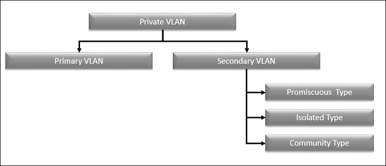
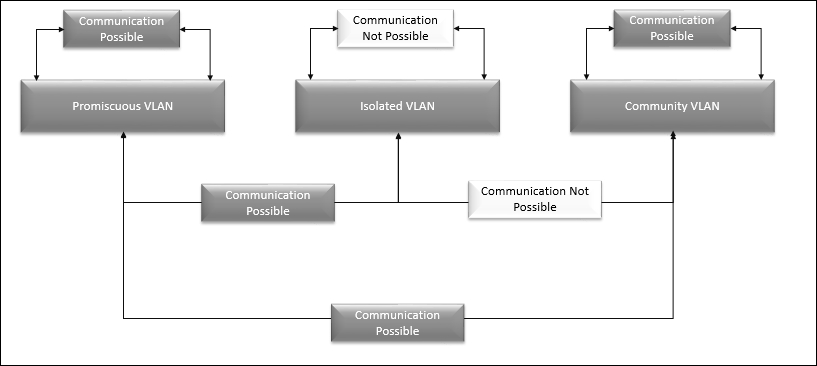
Now, let's explore the different types of Private VLAN to help with design essentials. Private VLAN is separated into two kinds: primary VLAN and secondary VLAN. Secondary VLAN is further classified into three kinds, such as promiscuous, isolated, and community types, as shown in the following diagram.
The following table illustrates the various definitions of PVLANs:
|
Classification |
Description |
|
Primary PVLAN |
The unique VLANs that have been alienated into smaller groups are said to be primary PVLAN. |
|
Secondary PVLAN |
PVLAN has a precise VLAN ID related to it. Each packet interconnects via its labelled data packet with a VLAN ID as if it were a usual VLAN. |
|
Promiscuous |
PVLANs can interconnect via the router to additional devices in other VLANs. A node devoted to a port in an immoral secondary PVLAN could send and receive packets to any other node in any other secondary PVLAN linked to the identical primary PVLAN. |
|
Isolated |
The isolated type will not interconnect to any other ports in the same inaccessible secondary PVLAN or from a community PVLAN. A node devoted to a port in an inaccessible secondary PVLAN could transfer packets from a promiscuous PVLAN. |
|
Community |
The community kind will neither interconnect to nodes in other community secondary PVLANs nor interconnect to nodes in an inaccessible secondary PVLAN. |
The following diagram illustrates the communication mechanism between each of PVLAN types specific to the secondary PVLAN:
In your design, if you want to use PVLANs, you need a physical switch that can support PVLANS. Not all physical switches support PVLANs. Make sure that you identify the switch support while you choose the switches for your vSphere design.
The objective of using TCP Segmentation Offload (TSO) in VM and VMkernel NICs is to improve the performance of the network and reduce the CPU overhead for TCP operations over networks so that the host CPU can be used for many applications.
TSO resides on the path of physical transmission and VM NIC. This helps to improve the ESXi performance. Whenever TSO is enabled, the NIC divides larger data masses into TCP segments in place of the CPU. The host can use more CPU cycles to run applications.
We can allow TSO support on a VM via a boosted VMXNET adapter; in order to allow TSO in the Virtual Machine, it is necessary to alter the present VMXNET or elastic virtual NIC with improved VMXNET. This will help to make sure that the alteration has taken place in the MAC address. Also, certain prerequisites are available to enable TSO. For example, the VM should have one of the following OS:
· Red Hat Enterprise Linux 4 specific to 64-bit
· Red Hat Enterprise Linux 5 specific to both 32-bit and 64-bit
· SUSE Linux Enterprise Server 10 specific to both 32-bit and 64-bit
· Microsoft Windows Server 2003 Enterprise Edition with Service Pack 2 specific to both 32-bit and 64-bit
Choosing the right virtual switch
After designing the physical network layer, the next step is to design the access layer where the VM will interact with the physical switch. In this chapter, you have learned enough about the design of VSS and VDS earlier. By now, you should have a broader understanding of the benefits and usability of both virtual switches; each kind of virtual switch has its own set of merits and demerits.
Let's get started by comparing VSS to VDS. Some of the following features are available on both kinds of virtual switches:
· Capacity to move L2 frames from one stage to another stage
· Capacity to perform section traffic in VLANs
· Capacity to utilize and accommodate the 802.1q VLAN encapsulation
· Capacity to put up one Uplink, which involves nothing but teaming with NIC
· Capacity to handle traffic shaping for the TX egress's outbound traffic
On the other hand, the following features are only available in VDS. Hence, you should preferably pick a virtual switch that will preferably go with VDS:
· Inbuilt capacity to shape inbound (RX ingress) traffic
· Inbuilt capacity to use insistent network VMotion
· Inbuilt capacity to centrally manage VDS via vCenter
· Inbuilt capacity to support PVLANs and LACP for dynamic link aggregation configuration
· Inbuilt capacity to handle load-based NIC teaming
· Inbuilt ability to import/export VDS configurations
Ethernet capacity sizing
Modern datacenters and enterprises believe that 10 GB has more benefits than 1 GB. Some of the facts that follow on from this are:
· It is always recommended that you use two 10 GB for HA, which will provide greater redundancy over 10 or more 1 GB Ethernets
· Using 10 GB Ethernet decreases the quantity of ports demanded when likened to 1 GB Ethernet
· 10 GB requires fewer ports; wires between systems will be reduced
Although 10 GB Ethernet can deal out welfare to a VMware vSphere infrastructure, several considerations should be taken into account while designing infrastructure with 10 GB Ethernet; these are tabulated in the following table:
|
Components |
Essentials |
|
Datacenter physical network cable |
Design essentials should consider the limitations of network design, and correct recommendations, such as Cat-6A cabling should be considered as a mitigation. |
|
Datacenter physical switches |
Most vendors offer 10 GB Ethernet-based capable switches. When we design our virtual datacenter, we should take into consideration our current and future demands as well. |
|
Ethernet network partitioning in hardware |
Let's assume that you opted to go for 10 GB Ethernet; on your design, don't allot 10 GB Ethernet for IP storage or vMotion. As we discussed earlier, some vendors offer the capability for the classification of a single 10 GB Ethernet link in hardware, so we can classify the classes as follows: · 3 GB for IP storage · 3 GB for VM traffic · 2 GB for FT · 1 GB for a management port · 1 GB for vMotion |
A majority of vSphere designers include 10 GB Ethernet in their designs, this provides an alternate solution to inflexibilities offered by multiple 1 GB Ethernet NICs; potentially, though, another way to remove those rigidities is to use a new technology called I/O virtualization.
Choosing the right enhancers
In vSphere's latest version, a lot of network enhancements, such as the following ones, are made by providing more flexibility to systems:
· Network I/O Control
· NetQueue
· SR-IOV
· DirectPath I/O
Let's get started with the VMware vSphere Network I/O Control. This provides support while partitioning the network capacity during contention. Network I/O Control delivers add-on control over the utilization of bandwidth in the form of network limits and isolation. VMware vMotion processes provisional network traffic that tries to eat as much bandwidth as possible.
VMware vSphere Network Resource Pools regulate the bandwidth against VDS. On every VMware vSphere network, the input/output control option is set to be enabled.
The VDS traffic is divided into the components of VMware vSphere Network Resource Pools, as follows:
· Management
· Fault tolerance
· NFS
· vSphere replication
· vMotion
· VM
· iSCSI
VMware vSphere offers the preceding components as user-specified:
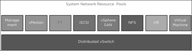
We are also allowed to form network resource pools to control VM traffic through the bandwidth by configuring its physical NIC dividends and host boundary. The following diagram illustrates the Network I/O logical design:
In a nutshell, VMware vSphere Network I/O Control helps to configure rules and policies at the VM level and ensures that Input Output resources are continuously obtainable for our mission-critical applications. Network I/O Control monitors the network. When it sees mobbing, it robotically diverts resources to our highest-priority applications.
NetIOC arms administrators with the following capabilities:
|
Type |
Description |
|
Isolation |
This aids traffic isolation so that a provided flow will never govern others and foil drops. |
|
Shares |
This helps to allow elastic networking bulk partitioning to deal with overcommitment when flows compete for same resources. |
|
Limits |
This limits the administrative traffic bandwidth frontier on the whole VDS set of dvUplinks. |
|
Load-based teaming |
This uses a VDS set of dvUplinks for networking volume. |
|
IEEE 802.1p tagging |
These tag outbound packs from the vSphere ESXi host for proper treatment by physical network capitals. |
Thanks to NetIOC, our administrators can be more productive. We can extend virtualization across more workloads, and our virtual infrastructure can become more versatile.
Let's look at the enhancer that is available. VMware vSphere NetQueue offers the benefit of the volume of network adapters to carry network traffic to the ESX/ESXi host in many received queues that can be managed distinctly, thus permitting them to be mounted to numerous CPUs and refining the networking performance of the receive-side.
The kernel feature of VMware vSphere is NetQueue, which offloads packet routing to VMs on the VMware ESX host, thus releasing CPU resources and reducing latency. NetQueue permits all the virtual network adapters to have a network queue in place of one common queue.
From ESX 4.0 onwards, by default, VMware hosts are enabled on all NetQueue.
The following syntax helps to check whether the configuration is accurate:
#esxcfg-module -g bnx2x#esxcfg-module-gs2io (for the Neterion) #esxcfg-module-g ixgbe (for the Intel)
Next, remember that there is no strategic technique defined from VMware to test this. NetI/O meter and IxChariot are two third-party tools that will aid in tracing networks and can give a defined output of bandwidth and net load on RX/TX queues.
NetQueue is required to be configured on ESXi at three different levels:
· From the ESXi OS level, enabled by default
· From the driver level
· From the hardware layer
A third enhancer is available. VMware vSphere DirectPath I/O is an efficient technology that is accessible from the latest version of VMware. It controls hardware chains, such as Intel VT-d and AMD-Vi, and in turn, allows guests to directly access hardware schemes. VMware DirectPath I/O will not support many structures, such as memory overcommit, vMotion, physical NIC sharing, and NetIOC. As a result of this, it is recommended that you use DirectPath I/O only for heavy jobs with very huge packet rates.
Enabling passthrough devices provides the means to use resources efficiently and improve the performance of your environment. You can enable the DirectPath I/O passthrough for a network device on a host.
VMware vSphere VMDirectPath gives the guest OS direct access on an I/O device, avoiding the virtualization level. This passthrough, by pass, or direct path can provide a huge growth recital for a VMware ESXi host by applying a high-speed I/O policy on the devices:
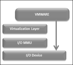
VMware vSphere VMDirectPath I/O can assist a guest OS whenever there is a need for a better recital from the ESXi host I/O device.
The difficulty of utilizing VMware VMDirectPath I/O is that a majority of the features will be unavailable, such as VMotion, record and replay, suspend and resume, fault tolerances, hot add and remove of virtual devices, DRS, HA, and snapshots. However, if we are using VMDirectPath 1/O on a CISCO UCS VM-FEX distributed system, it will allow us to have the features mentioned earlier.
A fourth enhancer is also available. VMware vSphere 5.1 and future releases provision Single Root I/O virtualization. We can use SR-IOV to interact with VMs that are inactivity-sensitive or require extra CPU resources.
Single root I/O virtualization is a description that permits only a Peripheral Component Connect Express on a physical device below a single root port to seem as multiple discrete physical devices to the host or VM:
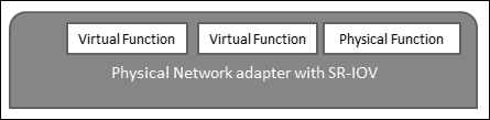
Single Root I/O virtualization utilizes the physical functions and virtual functions to accomplish global functions for SR-IOV devices. Physical functions are full PCI utilities that are proficient in arranging and running the SR-IOV functionality. It is designed to organize or switch PCIe devices using physical functions, and the physical functions have the full capacity to change data flows in and out of the systems. VFs are lightweight PCI, meaning that they support data flows, but have a limited set of configuration incomes.
The number of virtual functions delivered to the host or VM will be contingent on the device. PCIe devices enabled by SR-IOV involve good BIOS and hardware chains as well as SR-IOV chains in the VM driver or host instance.
Adapting the ESXi server architecture to accommodate the network
The architecture of ESXi servers can have a great impact on our vSphere network design in different ways. A few of the comprehensible effects on your network design include the following (it is worth considering these components on your server specifications):
· The ESXi server design controls a number of dissimilar network interfaces and dissimilar types of network interfaces (1 Gb or 10 Gb Ethernet) that are available
· The ESXi server design regulates the redundancy that we can offer for network communication
· The ESXi server design should include components that are required to be considered, such as blade server or rack-mounted server, which will shake the overall network topology
· The ESXi server design should include components that are required to be considered, such as chipset architecture, which will shake the PCIe slot performance
As we can see, quite a few factors have a great impact on our network design. In some scenarios, these influences might really push the design in deviating directions! It's up to the virtualization architect to resolve these factors with functional and nonfunctional requirements, restraints, and hazards as you build the network design.
Designing a vSphere network
After understanding the design of VSS and VDS, it is now time to read about designing a network for the virtual datacenter, aligning to design framework factors that need to be considered, such as availability, performance, management, and recoverability.
Readiness
When we design our network infrastructure and iron out a single point of failure, always consider high availability, including two switches, two routers, two NICs for the ESXi host, and two power supplies. The readiness of our design should focus on traffic, such as management traffic, IP storage, applications, VM, IP-based storage, vMotion and fault tolerance traffic. You can use the following techniques to accommodate the aforementioned factors:
· Make sure that your design uses multiple physical NIC ports on ESXi.
· Make sure that your design uses multiple physical switches on your network.
· Make sure that your design uses physical switches that are itself as resilient as likely.
· Make sure that your operational aspects are considered. Your teams should be skilled enough to handle a virtualized datacenter.
Performance
When we design our infrastructure, there would be a 10 GB Ethernet NIC for your organization network management stack, alternative for resilience, two for IP storage, and some other for VMs and vMotion. Consider the following components for optimal performance across your design:
· Management network
· ESXi NIC vMotion
· ESXi NIC for IP storage
· Virtual Machine vSwitch and vNICs
Management
When we design our infrastructure, we can replicate two major zones to make sure that the network is as controllable as possible . Both of these zones fall under the operational phase of the vSphere design:
· A management pane is required for a remote administrator to manage devices
· Naming standards and IP reservation
Recoverability
To make sure that the design of the network is capable of recovering on its own, we should consider the following:
· Backups of the network device configurations and setting an interval threshold for the backups
· Setting up a standard technique for scripts that can effortlessly recreate the vSwitch configuration in exactly the same way as it was previously
· Periodically documenting all the changes that are made to our infrastructure
· Creating a procedure and process to best meet the preceding requirements
It is worth considering the preceding essentials and recommendations on our design. In the next section, we will see the maximum configuration that is allowed in vSphere 5.5.
Network configuration limits
The following limits represent the achievable maximum configuration limits for networking in an infrastructure:
|
Component |
Configuration |
|
For physical NIC, this is the number of e1000e 1 Gb Ethernet ports |
24 |
|
For physical NIC, this is the number of igb 1 Gb Ethernet |
16 |
|
For physical NIC, this is the number of tg3 1 Gb Ethernet |
32 |
|
For physical NIC, this is the number of bnx2 1 Gb Ethernet |
16 |
|
For physical NIC, this is the number of nx_nic 10 Gb Ethernet ports |
8 |
|
For physical NIC, this is the number of be2net 10 Gb Ethernet ports (Serverengines) |
8 |
|
For physical NIC, this is the number of ixgbe 10 Gb Ethernet ports |
8 |
|
For physical NIC, this is the number of bnx2x 10 Gb Ethernet ports |
8 |
|
For physical NIC, this is the number of Infinib and ports |
1 |
|
For physical NIC, this is the number of combinations of 10 Gb and 1 Gb Ethernet ports maximum can be configured |
Eight 10 Gb and four 1 Gb ports |
|
For physical NIC, this is the number of mlx4_en 40 Gb Ethernet ports |
4 |
|
For VMDirectPath, this is the number of VMDirectPath PCI/PCIe devices per ESXi host |
8 |
|
For VMDirectPath, this is the number of SR-IOV Number of virtual functions |
64 |
|
For VMDirectPath, this is the number of SR-IOV Number of 10 G pNICs |
8 |
|
For VMDirectPath, this is the number of of VMDirectPath PCI/PCIe devices per VM |
4 |
|
Total number of virtual network switch ports per host (VDS and VSS Ports) |
4096 |
|
Total number of maximum active ports per host (VDS and VSS) |
1016 |
|
Total number amount of virtual network switch creation ports per standard switch |
4088 |
|
Total number of port groups per standard switch |
512 |
|
Total number of static/dynamic port groups per distributed switch |
6500 |
|
Total number of ephemeral port groups per distributed switch |
1016 |
|
Total number of ports per distributed switch |
60000 |
|
Total number of distributed virtual network switch ports per vCenter |
60000 |
|
Total number of static/dynamic port groups per vCenter |
10000 |
|
Total number of ephemeral port groups per vCenter |
1016 |
|
Total number of distributed switches per vCenter |
128 |
|
Total number of distributed switches per ESXi host |
16 |
|
Total number of VSS port groups per ESXi host |
1000 |
|
Total number of LACP-LAGs per ESXi host |
64 |
|
Total number of LACP Uplink ports per LAG (Team) |
32 |
|
Total number of hosts per distributed |
1000 |
|
Total number of NetIOC resource pools per VDS |
64 |
|
Total number of link aggregation groups per VDS maximum can be configured |
64 |
Here, the VM traffic drives via vSwitch 1, and vSwitch 0 grips management traffic on vmnic 0, followed by vMotion on vmnic 1. On vSwitch 2, IP storage goes through vmnic 4, and FT goes through vmnic 5. Take a look at the following diagram:
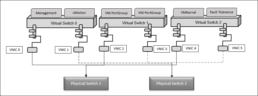
We have resilience for all modules, but the FT and IP storage traffic should have only one vNIC respectively. Based on your sizing of the virtual environment, this power may not provide enough, hence size it properly according your requirements.
Design considerations for networks with industry inputs
Here are some of the key design considerations followed worldwide by experts. Consider using some of them:
· Ensuring that vMotion and FT traffic are encrypted in your design; if not, it will result in security breach.
· Planning whether to use Microsoft NLB in your design or not. It's a decent awareness to select "No" to inform switches about VM MAC discourse deviations.
· Considering whether to include VM sizing and functionality into a version when sizing your vMotion network.
· Choosing to opt for a NIC that chains jumbo frames, NetQueue and TCP, and checksum offload to boost your design and achieve better performance.
· Limiting and sharing Network I/O Control in your design.
· Choosing a route-based policy on physical NIC load balancing in your design.
· Using a virtual infrastructure, such as vShield App, in your design. This will segregate DMZ traffic from the production network, provided this is sanctioned by the corporate security policy.
· Using 1 Gb Ethernet in your design. We must have minimum of one supplementary NIC to accompaniment the onboard NICs for resilience and feast groups across them.
· Using VDS in your design with the NFS/iSCSI option set and vMotion traffic on separate active uplinks.
· Using antimalware security in your VMs design. VMware recommends using the vShield Endpoint solution.
· Using VDS in your design. Make sure that the vMotion and NFS/iSCSI traffic has been routed via dedicated active physical uplinks for traffic.
· Using many dual or quad 1 Gb NIC in the VMware ESXi host; this is for the very purpose of isolating the physical NICS for each vSwitch on varied cards.
· Using active or additional uplink formations on your port groups if in case we need to isolate traffic while utilizing the VDS.
· In your design, if you plan use a multi-NIC vMotion formations on your cluster, each of the VMkernel interfaces contributing in the vMotion should have the IP addresses to the similar IP subnet.
· In your design, if you plan to use two 10 GB network adaptors, use a VDS with NetIOC and form the boundaries and dividends for the dissimilar traffic to consume.
· Considering the availability of numerous physical NIC ports as a portion of a one vSwitch.
· Using the Promiscuous mode for IPS. It's better to design a distinct vSwitch and relate it to suitable policies.
· Using port channels in a virtual environment and making sure that all NICs are active and belong to the same port channel.
Summary
In this chapter, you read about the VMware vSphere Networking essentials, the design of VMware vSphere standard and distributed switches, factors that influence virtual networks, the design of VMware vSphere Network, and design considerations for the management layer with industry inputs. In the next chapter, you will learn how to design VMware vSphere Storage.
All materials on the site are licensed Creative Commons Attribution-Sharealike 3.0 Unported CC BY-SA 3.0 & GNU Free Documentation License (GFDL)
If you are the copyright holder of any material contained on our site and intend to remove it, please contact our site administrator for approval.
© 2016-2026 All site design rights belong to S.Y.A.