Make: 3D Printing (2014)
Part VI. Finishing Techniques
Chapter 13. Post-Processing Your Prints
Friction weld, rivet, sand, paint—arm yourself with simple tools and finishing techniques to take your 3D prints to the next level.
Matthew Griffin
Andrew Baker
People often claim 3D printers can “make you anything you can imagine.” Dial up the digital model you want, hit “Go,” and the machine hums to work, producing an object accurately and repeatably. But as an astute eight-year-old pointed out to me when I handed her two of my favorite printed models at Maker Faire Bay Area last year, the results don’t always match your intentions.
“That octopus is red! A TARDIS is not supposed to be yellow!” she wailed, and knocked my offerings away.
While overall shape and mechanical fit are valued more highly than surface treatment in today’s desktop 3D printing, it’s sometimes worth judging a print by its cover.
I’m reminded of advice I got from a pair of industrial design professors at Pratt, after I showed them my print of a fluorescent-green clockwork mechanism: “It is worth enormous effort to make prototypes look like they were created from real-world materials.” Even the most creative engineers and business people will have difficulty seeing your prototype as a machine when it looks like a toy.
The domain of finishing techniques (i.e., everything that takes place after printing) is the craftsman’s workshop, where patience, tools, skills, and experience can transform the raw products of these machines into fully realized models. Like builders of dollhouses and model trains, many 3D printer jocks appreciate a loving and accurate rendering of a miniature world.
The results are impressive, but why should you tackle these craft skills when you could spend that time printing more plastic objects?
Makers who have mastered finishing techniques are granted wizard status by fellow 3D practitioners. Take artist Cosmo Wenman, who creates pieces that accurately mimic distressed metals and stones, and sculptor Jason Bakutis, whose sanded, painted, and polished faux marble and jade prints look remarkably like the real thing. Through careful work, pieces printed in crazy pink, green, and translucent filaments are made to resemble clay, stone, metal, and wood. How do they do that?
Tools and Materials
§ Benchtop vise such as a PanaVise
§ Pliers, combination (aka lineman’s pliers)
§ Pliers, needlenose
§ Multitool
§ Safety goggles (I like DeWalt’s DPG82-11C clear anti-fog model)
§ Respirator for sanding/particulates (I use 3M’s 8511 particulate respirator)
For friction welding:
§ High-speed rotary tool with 1” and 3/32” collets, such as a Dremel
§ Filament for 3D printer, ABS or PLA
For heating/reworking:
§ Hot air SMD rework station (Figure 13-1) or other small heat gun
§ Soldering iron and solder
§ Brass tube to fit snugly over your soldering iron tip
§ Metal plate or mirror (optional) for fast cooling
§ Nail, steel, large (for cooling/pressing)
For trimming/grinding:
§ Deburring tool (I use Noga’s heavy duty NG-1 model)
§ Flush cutters (aka diagonal pliers) or wire cutters
§ Files, narrow, diamond grit
§ Coffee/spice grinder (for grinding filament)
For sanding/polishing:
§ Sandpaper: 80/100, 150, 220, 320, and 500 grits
§ 3M Wetordry Polishing Papers
§ Micro-Mesh Soft Touch Pads and Colored Sanding Sticks
§ Sanding/polishing/buffing disks for rotary tool
§ Novus Plastic Polish Kit
For filling/gluing/painting/sealing:
§ Acetone for use with ABS objects (not PLA)
§ Resealable container, acetone-resistant
§ Enamel hobby paints such as Testors
§ Acrylic paints
§ Clear-coat spray paints (I use Krylon Crystal Clear Acrylic, Matte Finish, and Triple Thick Crystal Clear Glaze; and Rust-Oleum Matte Clear and Gloss Clear).
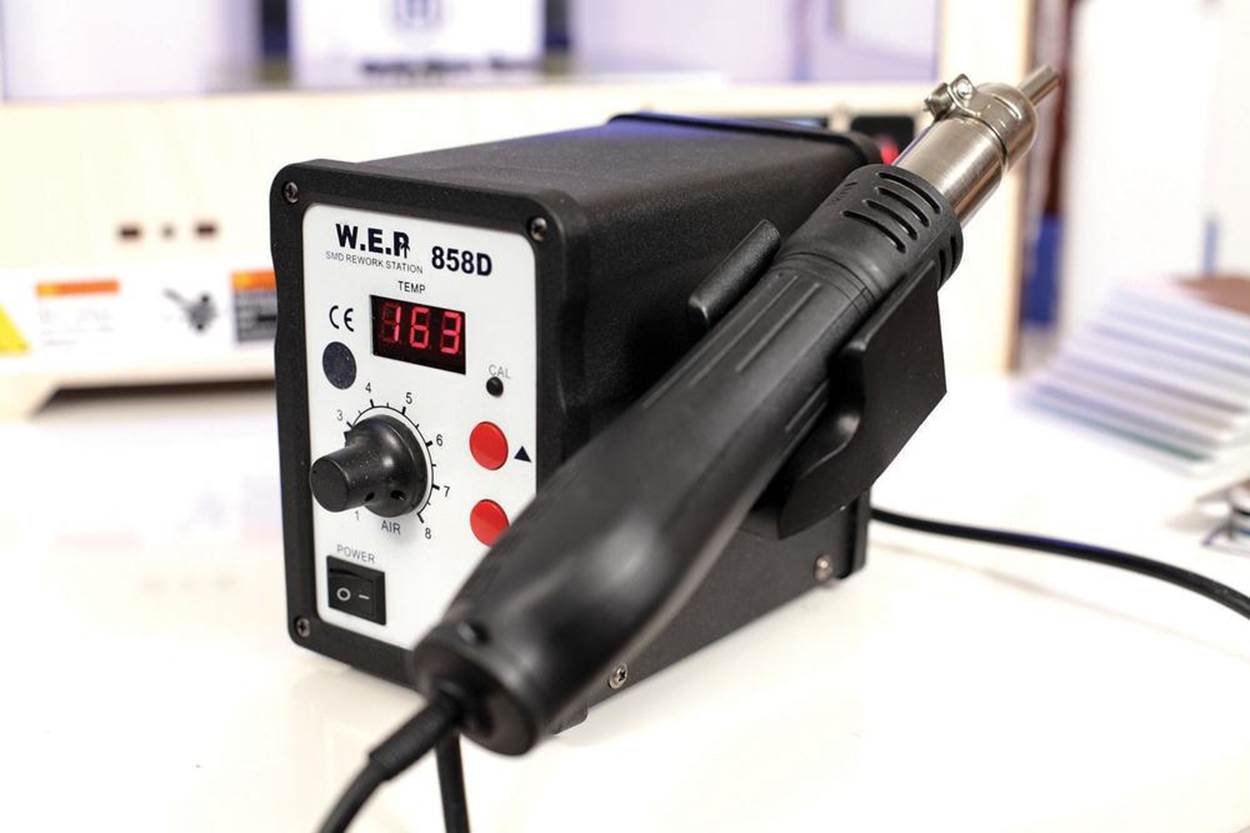
Figure 13-1. Hot air rework station
The desktop 3D printing community has a lot to learn from the sculptors, model railroad builders, and tabletop gamers now joining their ranks. And as my professors pointed out, these extra steps aren’t just cosmetic. Your capacity to transform your models into “magical” replicas is a crucial means of communicating your inventions.
Tricks of the Trade
Desktop 3D printing has yet to spawn third-party finishing services like commercial 3D printing did a decade ago. So, without access to acetone cloud chambers, multiaxis enamel jet robots, agitating chemical baths, and industrial tumblers and polishers, makers have rolled up their sleeves and discovered a host of finishing solutions using inexpensive tools and materials. These methods not only affect a print in post-production, but can often change the way we think about a digital model back in the initial design stages.
In researching my upcoming book Design for 3D Printing (MAKE, 2013), I’ve interviewed a wide range of members of the desktop 3D printer community. I’d like to share some of their promising tools and techniques. In turn, I hope that those of you refining new methods and sourcing better, safer, and cheaper products and techniques will also share.
Friction Welding
The world may have forgotten the Spin Welder toy sold by Mattel in the mid-1970s, but Fran Blanche of Frantone Electronics did a great job of recreating the experience in her 2012 video “Build Your Own Friction Welder.” Using an inexpensive rotary tool, Fran was able to spin a styrene rod fast enough to create a strong weld between two pieces of plastic that was difficult to break apart by hand. With the Spin Welder toy, children assembled the frames of helicopters, motorcycles, and other projects by fusing together beams and struts, then used plastic rivets to fasten the outer shell. Sure, it was potentially one of the most dangerous toys of all time, but I agree with Fran’s conclusion: why haven’t tools like these joined the maker’s toolbox?
Unlike adhesives or traditional welding, friction welding fuses metal or thermoplastic objects together by quickly spinning or vibrating one piece against another. Mechanical friction creates a melt zone shared by both parts, fusing them into one solid piece. In friction surfacing—a variant of friction welding—a piece rotated at high speed is moved across an edge or surface under gentle pressure to weld seams, patch gaps, or smooth surfaces.
These techniques are common for plastics and aluminum in the automotive and aerospace industries, but the tools are expensive. Sophisticated spin welders can spin parts at hundreds of thousands of RPMs for short bursts of even single-digit rotations, parking the fused part at a precise orientation. Where are the cheap, hand-tool equivalents?
As it turns out, many of us already have the equipment to experiment with friction welding. Dremels and similar high-speed rotary tools spin fast enough to melt 3D printer plastics, and printer filament can be used as welding “rod” to solidly fuse parts or close seams. These tools can also spin-weld 3D-printed rivets. And while it takes them a second or two to spin down again, the melting points are comparatively low, allowing for some manipulation after the fact to reposition the joined part.
I think both approaches—welding and riveting—are killer tools for 3D print finishing, particularly for “blind riveting” into the side of an object, and for joining parts made of PLA, which is typically much harder to glue than ABS.
Friction Welding Mismatched Surfaces
I spent some time with Chris Hackett from the Madagascar Institute learning how ideas from traditional metal welding might apply to friction welding 3D-printed parts. We experimented with the rotary tools in his workshop and came up with the following approach for creating a nice welded seam in plastic, similar to a traditional metal weld. When two printed parts don’t mate perfectly due to warp or poor planning, you can friction-weld them together as securely as if they were a single printed part. Here I’ll demonstrate with ABS parts and ABS filament. It works with PLA, too.
1. Prepare the Rotary Tool
Select the collet you need for trapping the filament you’ll be using. For 1.8 mm filament, use a 3/32” collet as shown here (three rings) and for 3 mm filament use a 1” collet (0 rings) (Figure 13-2).
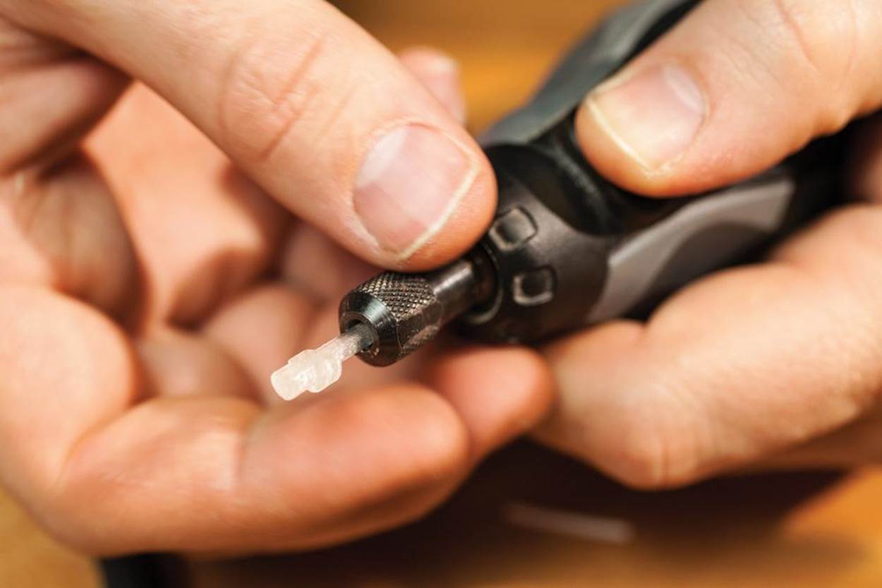
Insert a short length of filament into the collet jaws and tighten down the collet nut to secure it in place (Figure 13-3).
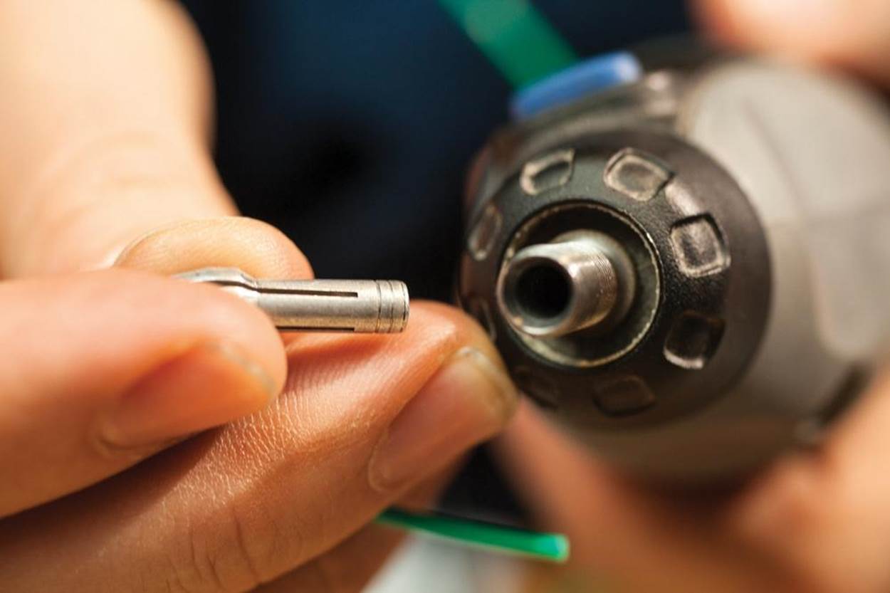
Figure 13-2. Preparing the rotary tool
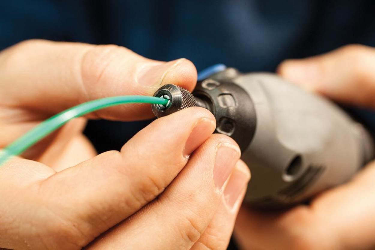
Figure 13-3. Insert filament into tool
Trim the filament about 1/2” from the collet. Short pieces are easier to control, and they spin on a tighter axis. (With experience you can use longer pieces, pressed gently at an angle, to make longer welds. You may need to straighten them by reforming them with a heat gun.)
2. Prepare Two Parts for Welding
After scraping and sanding, the two watch body cases shown in (Figure 13-4) meet with a gap that varies between 0.1 mm and 2 mm around the edges. That’s too sloppy for gluing, so I’ll weld them.
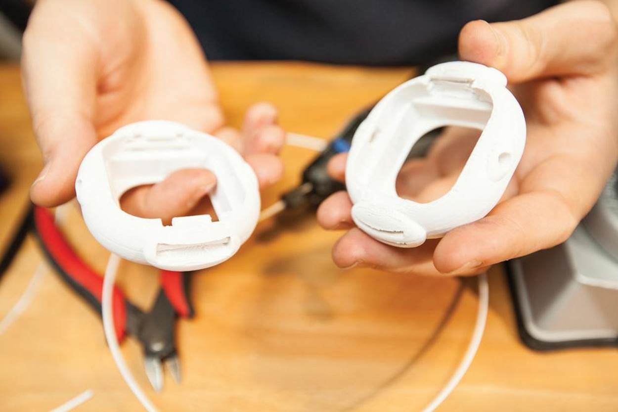
Figure 13-4. Prepare parts for welding
Use a deburring tool or razor blade to bevel the top edges of the seam where the parts meet, forming a narrow, V-shaped channel (Figure 13-5). Your goal is to create enough room for three welding layers, from the bottom of the bevel up to just above the surface of the two parts. This method gives a stronger bond than a weld that sits just on the surface.
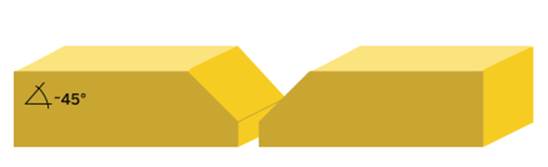
Figure 13-5. Bevel the top edges of the seam, forming a narrow, V-shaped channel
Warm both parts with low heat from a heat gun (Figure 13-6). This helps them receive the weld to the same depth. If one part is much larger than the other, focus extra attention on warming the larger piece.
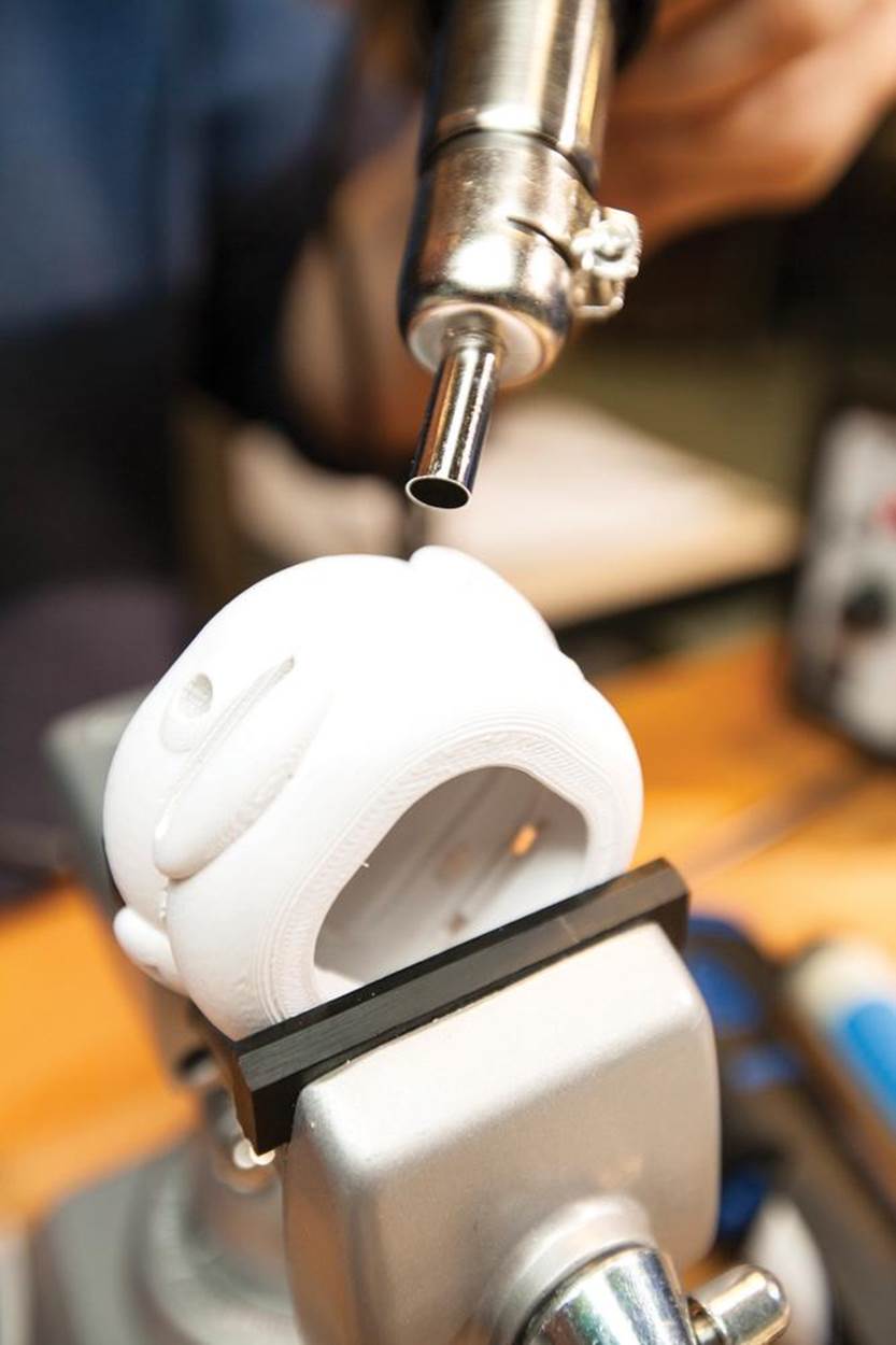
Figure 13-6. Warm the parts with a heat gun
3. Tack-Weld the Parts in Position
Now tack the parts together with a series of short spot welds, moving around the joint while holding the parts steady.
Spin up the rotary tool, and lower it until the spinning filament grazes both surfaces of the seam. When the tip of the filament begins to deform, apply a little pressure (Figure 13-7).
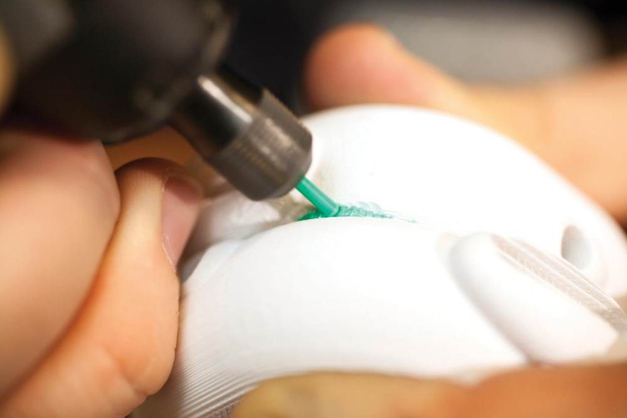
Figure 13-7. Applying pressure
Moving the spinning filament in tight little circles, widen the melt zone slightly into the sides of both parts, making a little forward progress with each circuit, until you’ve created a small spot weld (Figure 13-8).
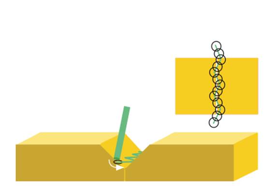
Figure 13-8. Spot welding diagram
Tack in three or more places along the seam and let the parts cool. They should be tacked tight, difficult to separate by hand (see Figure 13-9).
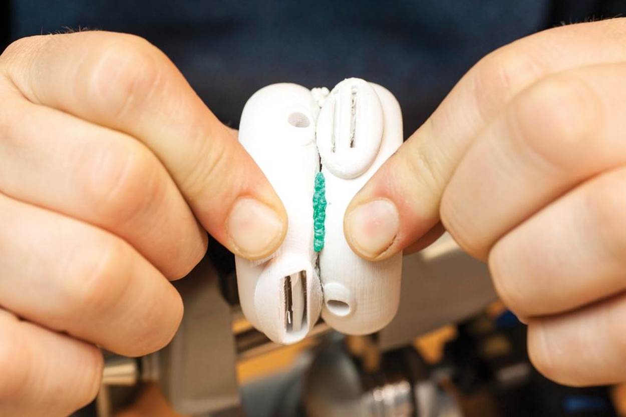
Figure 13-9. Tack the seam and let it cool
4. Plug Gaps with Filament
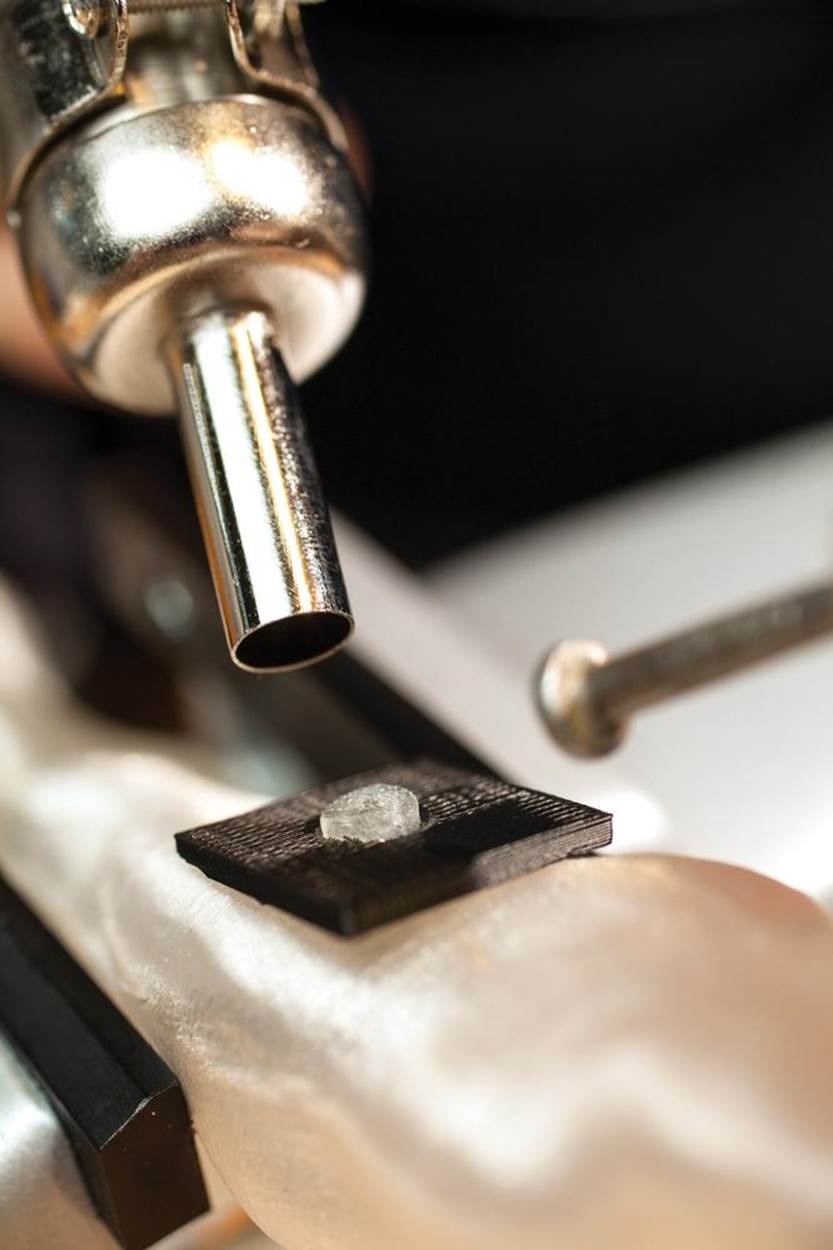
Gaps that are wider than half the width of your welding filament should be filled before welding a clean seam. Soften a short scrap of filament to use as filler, by using the low setting on a heat gun or by warming it to 100°C on your printer’s heated build platform (Figure 13-10).
Press the softened filament into the widest gaps between the two parts, making quick tack-welds if necessary to pin it in place.
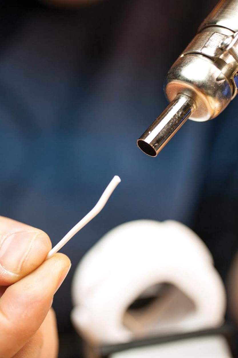
Figure 13-10. For large gaps, soften a short scrap of filament to use as filler
5. Friction Weld the Seam
Now weld the whole seam in two or three layers, as shown in Figure 13-11. A single weld would probably bond the parts at the surface only, allowing the seam to be broken if the parts are torqued.

Figure 13-11. Friction welding the seams, using several layers
In this idealized diagram, we weld one bead at the bottom of the seam, two beads on a second layer, and three on a third (top) layer, fusing the parts through their entire thickness.
To hide the weld, you can sand it back flush and then paint or seal the surface.
Friction Welding to Repair a PLA Model
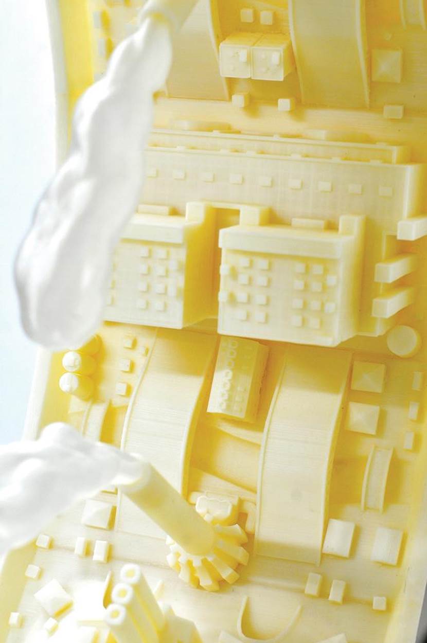
Punctured mysteriously by the TSA (Figure 13-12), a part from Micah Ganske’s sculpture Industrial Ring Habitat (see Figure 13-13 for context) needs a patch. We’ll use red filament to make the friction weld easily visible.
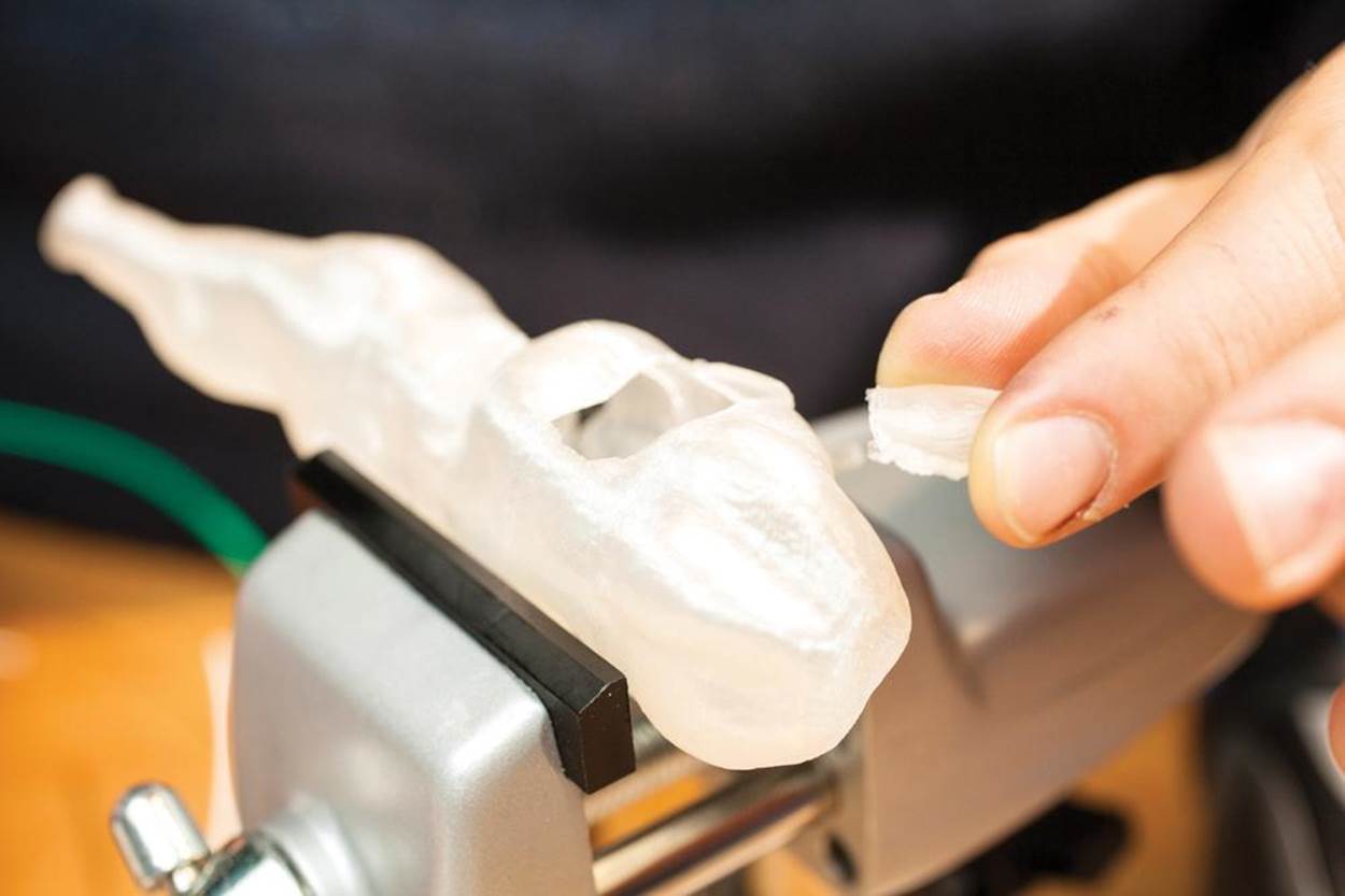
Figure 13-12. Punctured “Ring Habitat”

Figure 13-13. Industrial Ring Habitat, by Micah Ganske
PLA is prone to cracking and splitting, and it’s typically difficult to repair. Solvents such as acetone have little effect. ABS glue and super glue merely cement the parts by surface tension, rather than offering a chemical weld—meaning that the seam can easily be rebroken.
With friction welding, you can form solid joints that are difficult to break.
1. Press the patch or broken part into place and hold it securely:
2. Tack-weld the patch in place in a few different positions:
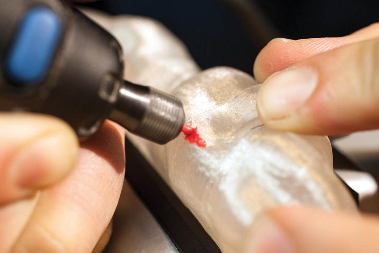
3. PLA is workable at lower temperatures than ABS, so use a gentle touch to melt and weld the two parts. Too much pressure can create a puncture. It takes a bit of practice:
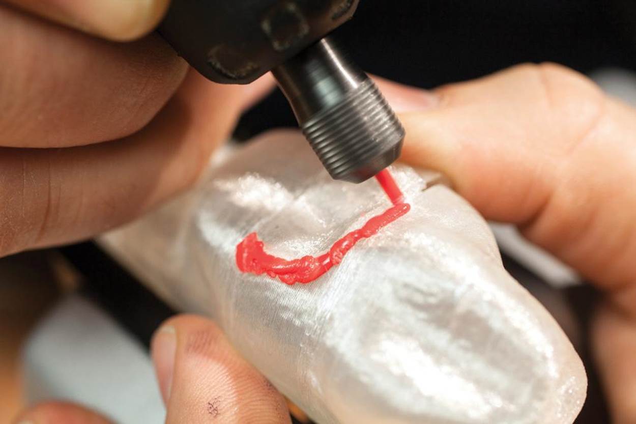
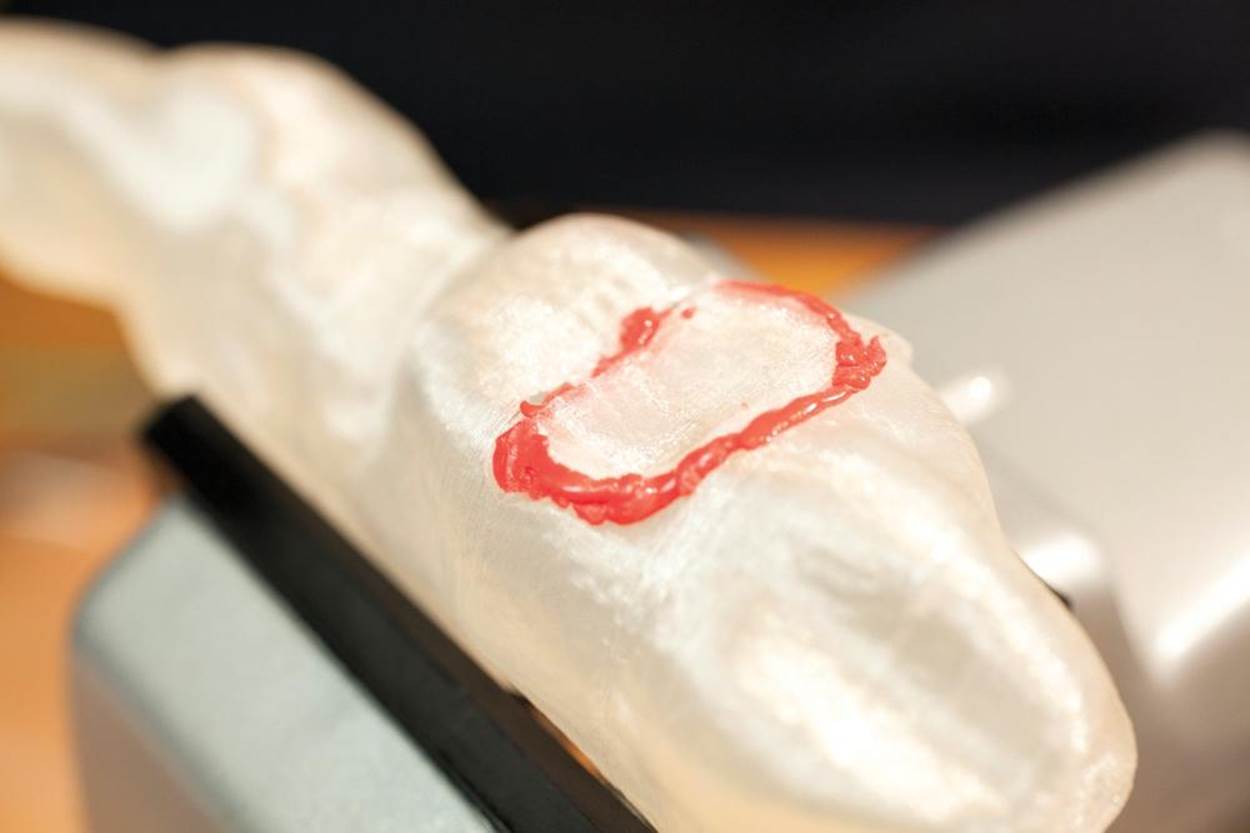
4. Move around the seam, changing direction as necessary for handling and control. For prettier welds, take frequent breaks to let the parts cool:
5. Let the completed seam cool to room temperature before sanding and sealing:
Riveting: Friction Welding Blind Rivets
A rotary tool can also be used to permanently fuse a spinning part to a fixed one, using a one-sided “blind rivet.” Blind rivets have one huge advantage over ordinary solid rivets: you don’t need access to both sides of an assembly to rivet its parts in place.
This method works well for attaching plastic panels to the outside of objects when access to the interior is awkward or impossible. It also lets you construct massive objects from multiple panels, each panel printed close to the bed of the printer for optimal printing.
Shown in Figure 13-14 are two 3D-printed blind rivets, next to a brass solid rivet and three aluminum blind rivets. Notice that the printed rivets, like the aluminum ones, have a “mandrel” that extends well beyond the rivet’s head. This is the part that’s gripped in the rotary tool.
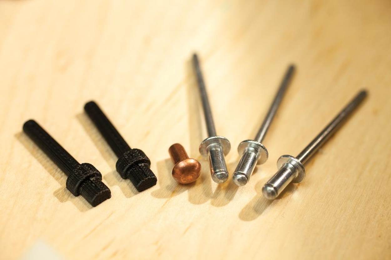
Figure 13-14. 3D-printed blind rivets, brass solid rivet, aluminum rivets
You’ll clip it off after the rivet is firmly in place. I designed the printed rivets to be gripped by the 1” collet, the standard size for most Dremel accessory bits.
Plastic rivets need not be perfectly cylindrical for friction welding, so I designed them “three-quarters” round, for printing flat on the platform (Figure 13-15). This way, the horizontal “grain” of the printed rivet helps strengthen it.
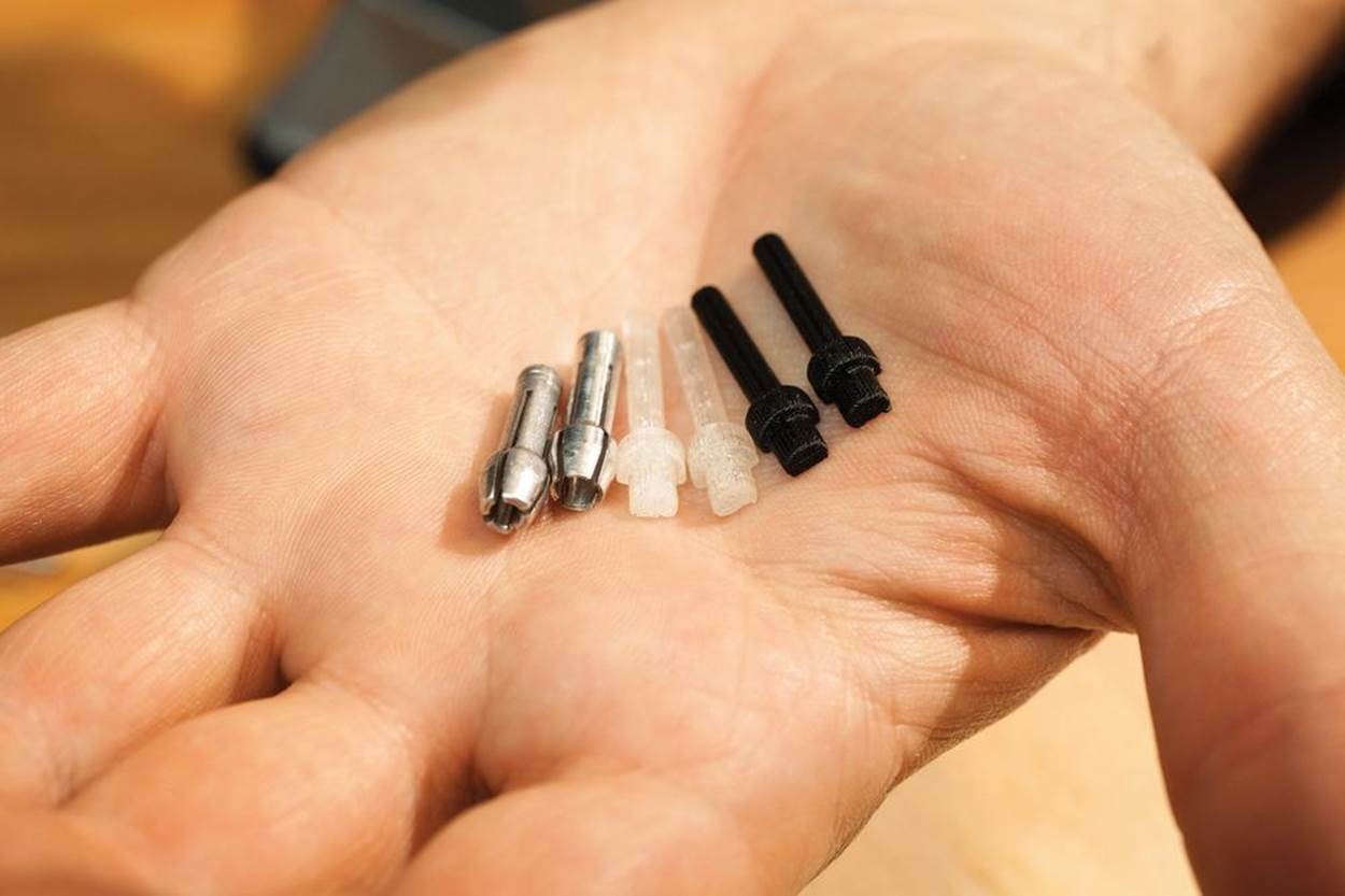
Figure 13-15. Three-quarters round rivets
I’ll demonstrate by riveting a small panel to the outside of another part. To print your own rivets, get the 3D files at http://www.thingiverse.com/thing:61510.
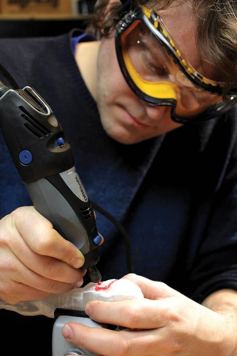
Friction welding involves the use of high-speed rotating tools and should not be attempted without ANSI-approved safety glasses. Welding and other operations that heat, soften, and melt plastic may release hazardous chemical vapors and should not be attempted without proper ventilation. Sanding and other dust-producing operations should not be attempted without a NIOSH N95-approved particulate respirator. Acetone and other volatile solvents should not be handled without proper ventilation, safety goggles, protective clothing, and latex or nitrile gloves.
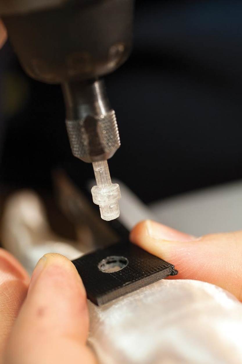
1. With the proper collet in place, loosen the collet nut and insert a plastic rivet:
2. Drill or design in mounting holes in your panel to provide clearance for the shaft of the rivet to pass through to the base part where it will be fixed. The hole should be narrow enough that the rivet’s head will pin the panel in place.
Pre-drilling (or designing) a pilot hole in the base part can help prevent your rivet from mounting off target:
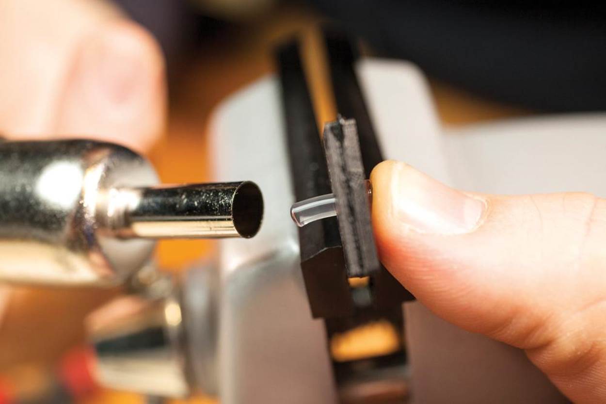
3. Spin up the rotary tool and gently insert the shaft of the rivet through the mounting hole until it contacts the mounting position. Continue spinning until the shaft of the rivet begins to melt and deform—then press it gently down into place:
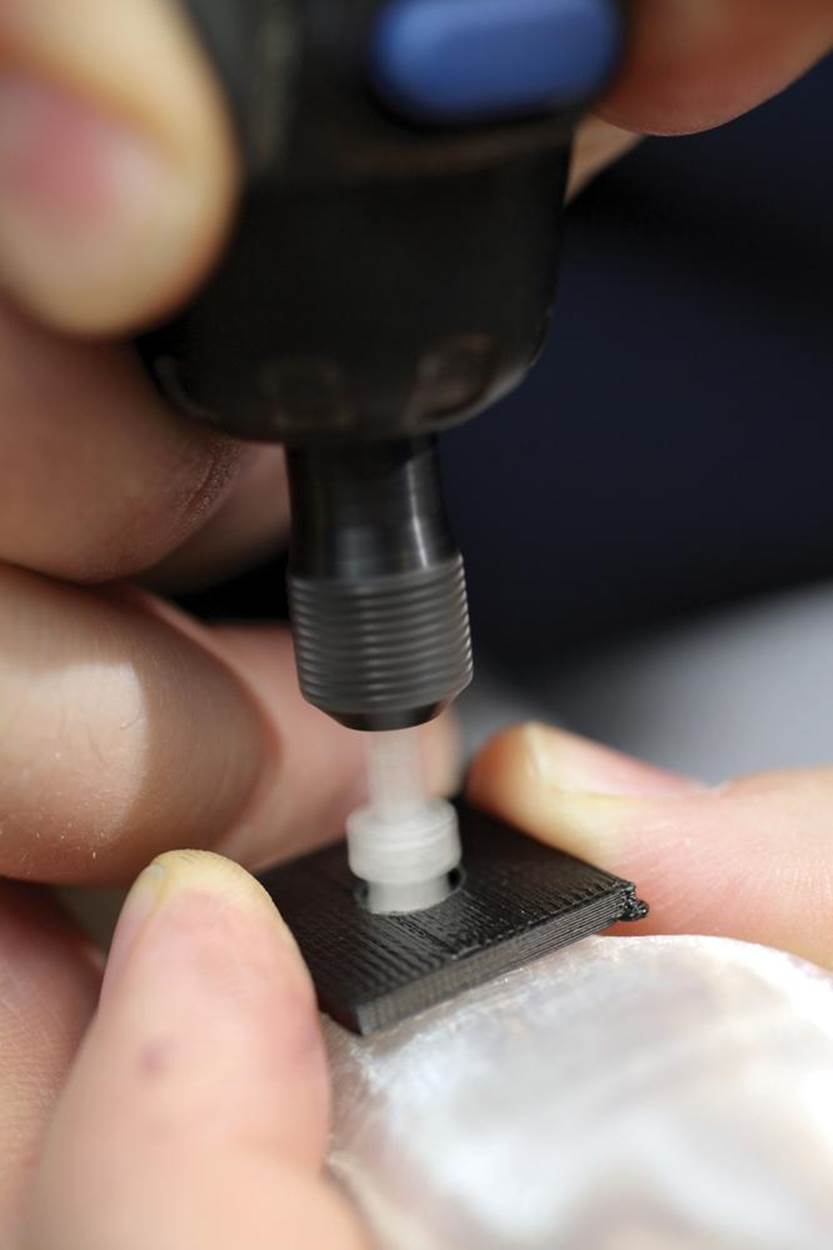
4. Stop the rotary tool and hold it steady in a fixed position at a right angle to the work, while applying a little downward pressure. It can help to use a piece of cardboard or foam as a friction brake to stop the rotation quickly (unlike a professional spin-welding tool, most rotary tools need a second or two to spin down).
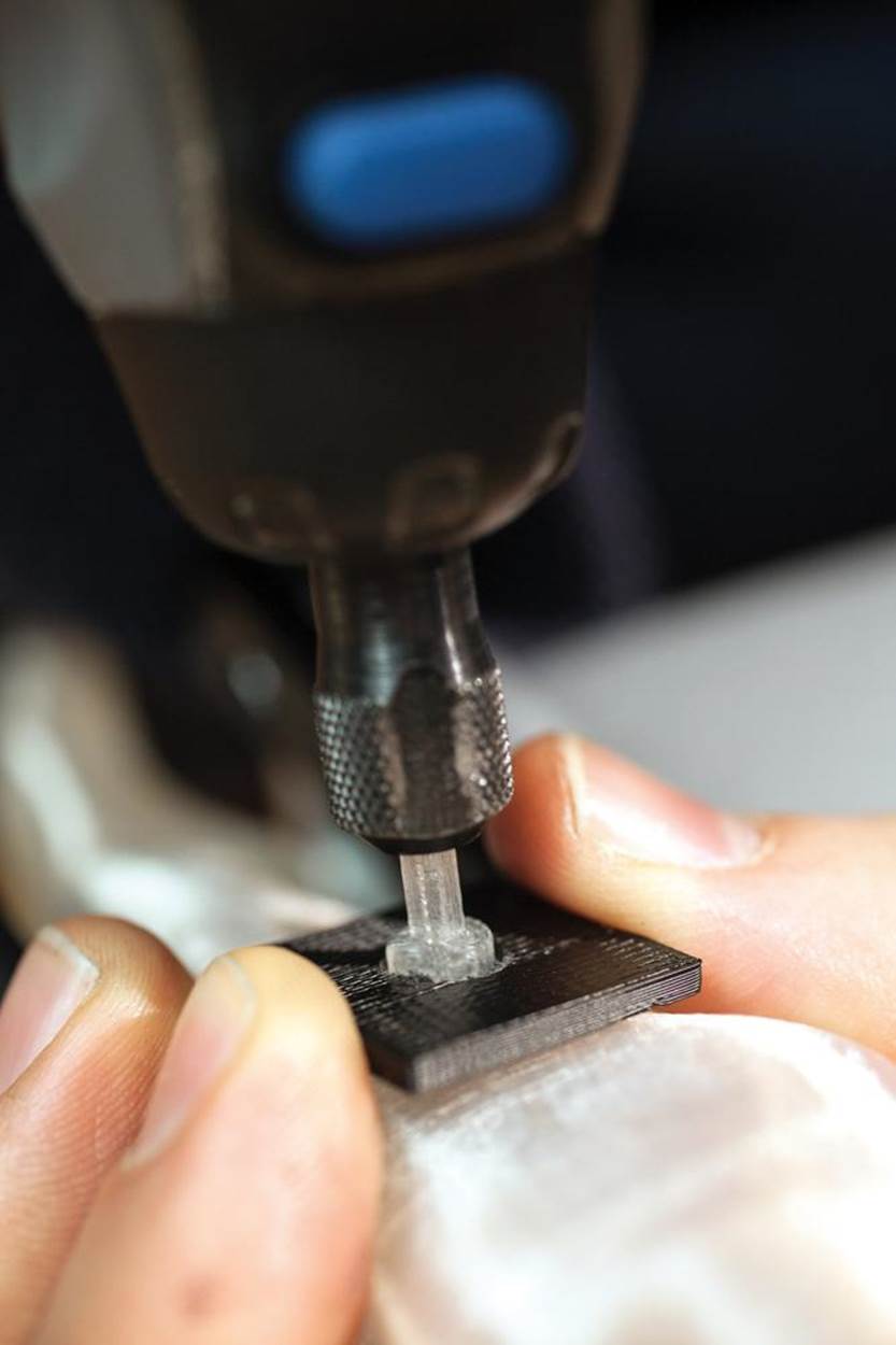
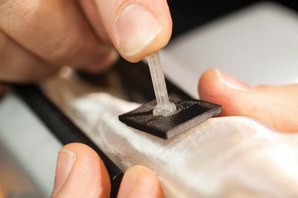
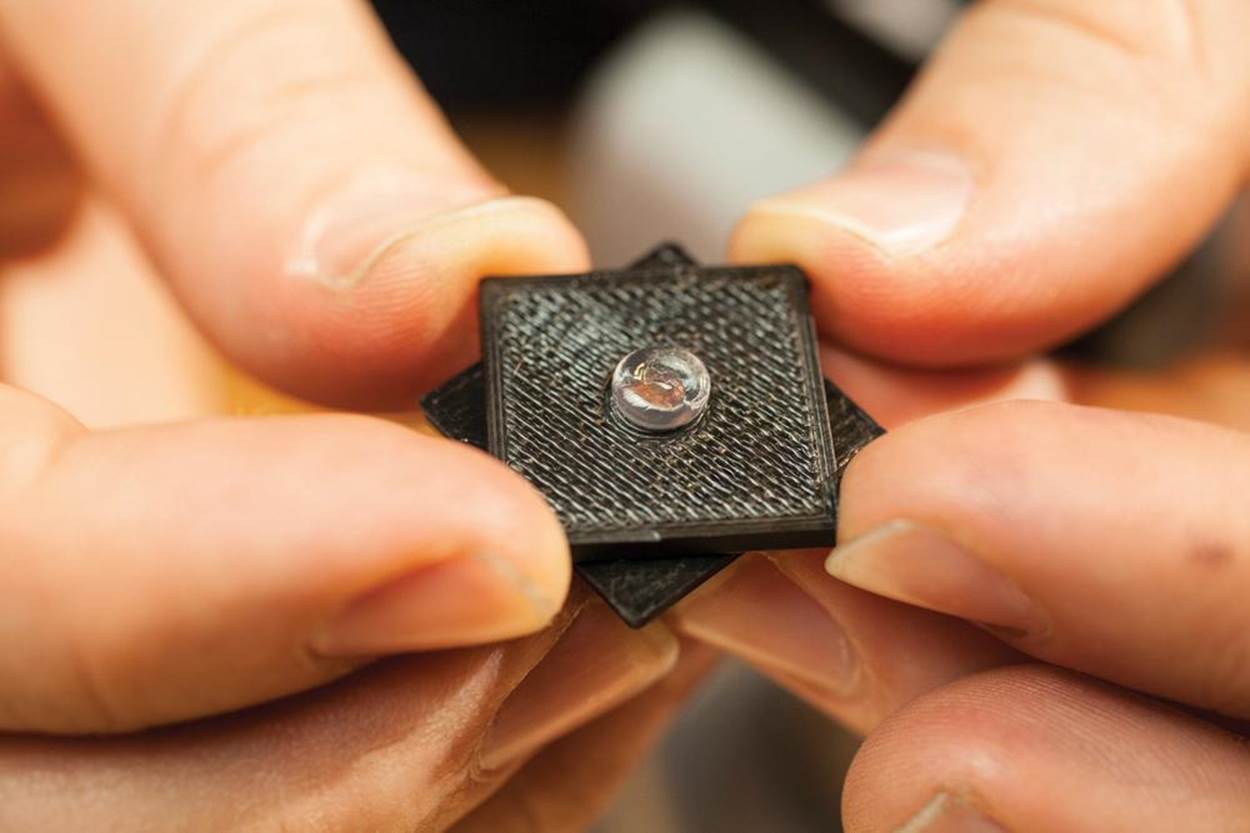
5. Loosen the collet nut and slip the mandrel of the blind rivet out of the rotary tool. If the rivet is still cooling, hold it in position until it’s fully cooled (at which point it should be entirely fused with its mounting point):
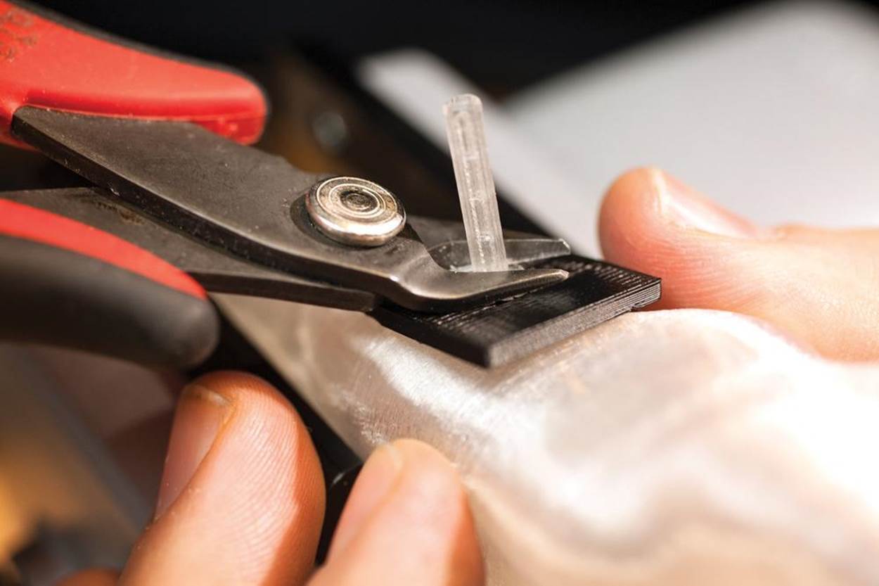
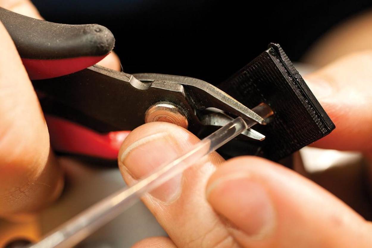
6. Using a flush cutter, snip off the mandrel, leaving the head intact:
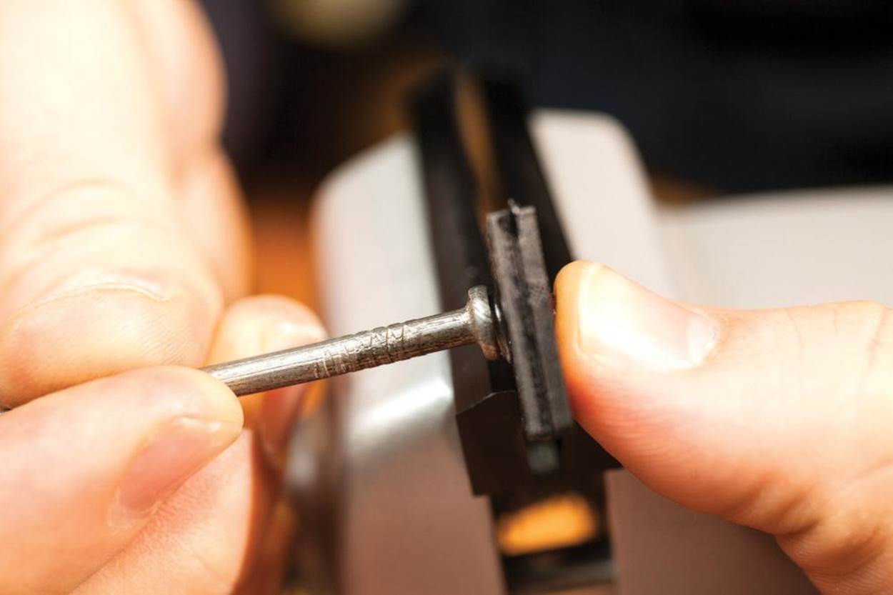
7. If the rivet head protrudes too far, has a sharp ridge, or seems too narrow to secure the panel in place, warm it with a heat gun and use the head of a steel nail to press it flat:
It’s possible to fuse ABS rivets to PLA, and vice versa, but you’ll need to find the “feel” for the initial friction stage before pressing down the body of the rivet. Before mounting delicate parts, test-rivet the materials you’ll be using.
Using Filament to Make Solid Rivets and Hinges
People have used rivets since the Bronze Age to fasten together tools, art, bridges, and buildings, so it’s no surprise that 3D printer users are experimenting with riveting techniques. We’ve seen a number of projects using pieces of filament as pins to hold together large assemblies.
Just recently, 3D artist and instructor Jason Welsh demonstrated a method for building his DIY electronics cases that promises to become a new power technique. His Folding Arduino Lab (Figure 13-16) and Pi Command Center each use filament “spikes” to create rivets and hinges.
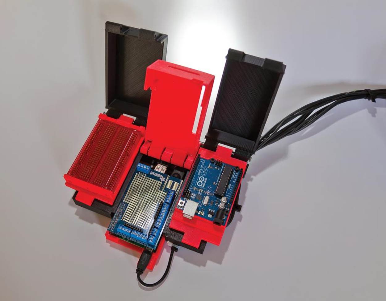
Figure 13-16. Pi Command Center
Essentially, Welsh uses heat to reform pieces of filament into straight rivets, flattening one head before inserting the rivet and the other head after the rivet is firmly in place. As with any solid rivet, you need access to both sides of the assembly, but the advantage of this method is the creation of strong fastenings that can be completely removed later using a flush cutter.
While you can make spikes with any filament, I recommend 3 mm PLA based on my experiences building Welsh’s project. PLA is easier to soften and work with a heat gun, and 3 mm spikes remain straighter and more rigid than 1.75 mm spikes after cooling. If you don’t have 3 mm filament, you can accomplish the same goal with 1.75 mm filament by using more rivets to distribute the load.
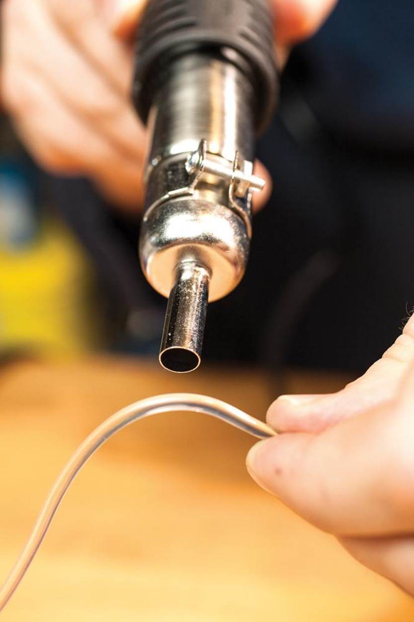
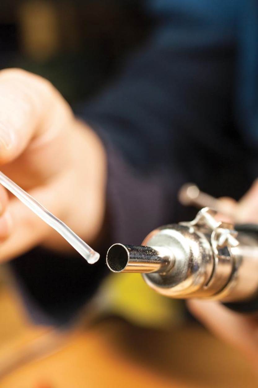
1. With a heat gun set to low, evenly warm a 4"–6” length of filament until it becomes limp (several minutes on a heated build platform works, too):
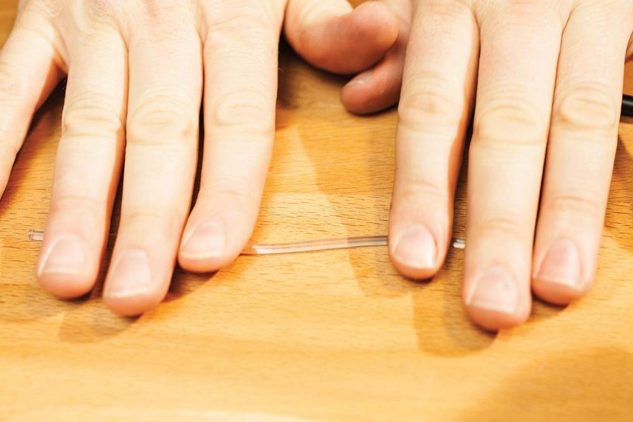
2. While the filament is still hot, straighten it by rolling it on a table, or better yet, on a piece of glass that will quickly cool it. Gently move both hands away from each other while rolling, to keep the filament straight as it cools:
3. Soften one end using a heat gun on a low setting (a soldering iron, heated brass nozzle, or heated build platform can work in a pinch):
4. Stop the rotary tool and hold it steady in a fixed position at a right angle to the work, while applying a little downward pressure.
It can help to use a piece of cardboard or foam as a friction brake to stop the rotation quickly. (Unlike a professional spin-welding tool, most rotary tools need a second or two to spin down.)
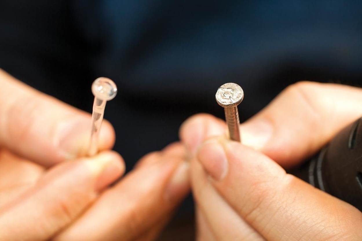
5. Tap the soft end of the spike on a flat, cool surface until it deforms into a flat rivet head. I tend to use a steel nail head, but any flat surface that can cool the filament rapidly will work:
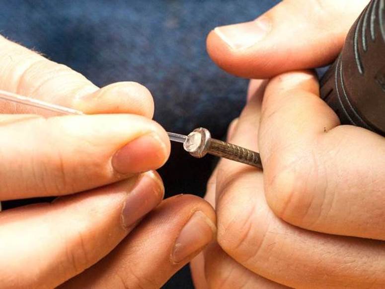
6. Your rivet should have a nice flat head, wide enough to rest firmly on the edge of the mounting hole. In rivet lingo, this is the “factory head,” as opposed to the second head or “shop head” you’ll create on the other end when installing the rivet:
7. Insert the rivet into the mounting point until the factory head is flush, then clip the tail a little ways beyond where you need the second head of the rivet:
8. Use a heat gun to soften the protruding tail of the rivet until it begins to deform:
9. Use a flat, smooth surface to press down and deform (“buck”) the tail, creating the rivet’s shop head. I find that a large steel nail head works best—it’s easy to handle and it cools the shop head quickly:

10. Continue to press tight, against the shop head as it cools, making sure it doesn’t relax away from the mounting point.
Don’t apply force to the assembly until both the rivet and the parts being assembled cool to room temperature.
Hold in place until cool as seen here:
1. Installation of a hinge rivet follows the same procedure, except at the very end.
After pressing the shop head, move the parts gently as they cool to ensure that the joint has enough play for the hinge to open and close easily.
In the completed assembly, the two black ABS plates can spin easily on the hinge without coming free.
TWO MATERIALS, TWO APPROACHES TO FINISHING TECH
ABS and PLA plastics have very different physical properties. ABS is printed at a higher temperature (typically 215–235°C), is more durable and flexible, and dissolves in industrial solvents like acetone. PLA can print at lower temperatures (starting at 180°C), wears down faster, can be brittle or shatter, and won’t dissolve in acetone. (The chemicals used to dissolve PLA are highly toxic.)
If you’d rather use a soldering iron than a heat gun, find a brass tube (Figure 13-17) that fits snugly over your iron. Use the brass tube to work the plastic, and keep your soldering tip clean. Make sure to clean your tube thoroughly so the plastic doesn’t stick to the brass.
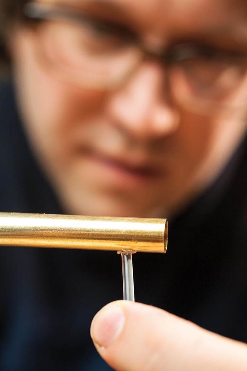
Figure 13-17. Protect your tip with a brass tube
Tape the factory head of the rivet in place when you need both hands to soften and flatten the shop head.
Gluing and Filling: Creating ABS Slurry for Filler and Glue
While super glue (cyanoacrylate) and plastic model glues do an excellent job of bonding ABS parts, many 3D-printed model builders have switched to using “ABS slurry” for both glue and filler material, because this substance can weld parts together more permanently and can be exactly color-matched to the printed parts. ABS slurry is simply ground-up ABS filament dissolved in acetone.
Applied in the open air, acetone melts the surface of ABS plastic (and many similar styrene plastics), creates a goopy sludge, and then—after some time—evaporates, leaving behind just the reformed ABS plastic. By sealing up this process in an airtight container that the acetone cannot easily escape, you can prepare a thick, even acetone/ABS mix similar to acrylic gel medium.
There are a variety of methods for preparing ABS slurry. I like ProtoParadigm’s recipe; one part ABS to two parts acetone, mixed in fingernail polish containers or similar. Use a cheap coffee/spice grinder to shred ABS filament and scraps as needed. Smaller pieces dissolve faster and make it easier to gauge the mix ratio.
Observe proper handling precautions when working with acetone and ABS slurry. Wear gloves and goggles and do not work without proper ventilation or in the presence of open flames. Besides being highly flammable, ABS slurry sticks to anything and burns with a foul-smelling smoke that is widely regarded as toxic. Be very careful or you’ll create a tiny batch of “napalm” that will need to be treated like a chemical fire.
Apply ABS slurry with an inexpensive natural-hair paintbrush (synthetic brushes will dissolve in acetone!) to either fill small cracks or glue two pieces together. Leave it to air-dry until the acetone completely evaporates, and your final part will have a joint or patch made only of ABS plastic.
Your exposure to acetone is greatest while applying ABS glue and immediately after, so pin your parts to a piece of cardboard or a tray that you can immediately move to a well-ventilated area away from your workspace. If you move them outside, protect them with a cardboard box to keep leaves, dust, and grime out of the still-goopy slurry.
While acetone can “weld” the edges of ABS parts to bond them, this joint lacks the shear resistance of parts printed together, because the “melt zone” doesn’t extend deep into the surface. If an assembly needs mechanical strength, design an interlocking joint with lots of surface area—or use hardware.
INDUSTRIAL RING HABITAT
Artist Micah Ganske used ABS slurry glue to assemble his groundbreaking sculpture Industrial Ring Habitat from 1,000 3D-printed ABS parts. He also uses it to glue PLA parts to ABS—even though acetone doesn’t dissolve PLA, the slurry seeps into cracks and crevices to mechanically bond the PLA parts to the ABS base.
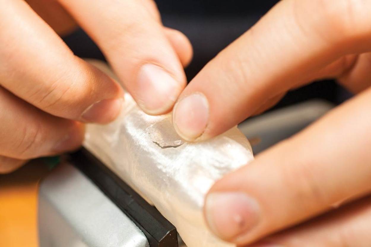
Sanding 3D-Printed Plastic Parts
When I first learned the basics of woodworking, I proved a lazy, inept sander of splintery plywood toolboxes and lopsided Pinewood Derby cars. My father suggested I forget about “sanded” as a goal, and focus on “sanding” as an activity. You cycle from coarse-grit sizes down to finer-grit papers until the surface is as smooth as you intend.
The same goes for sanding 3D-printed plastics (Figure 13-18). With ABS and PLA, you can work your way down to very fine papers indeed—3M gem-polishing papers and Micro-Mesh sanding tools with single-digit micron grits that create scoring patterns invisible to the naked eye.
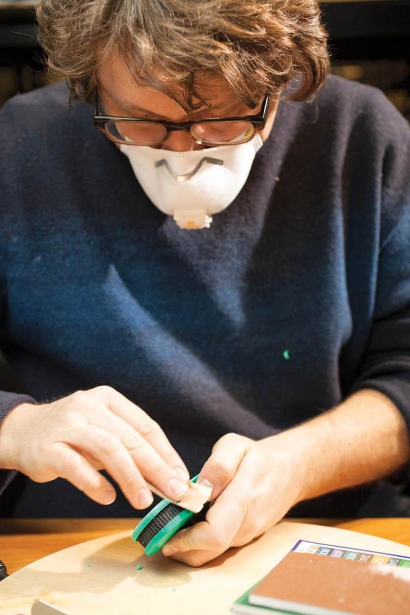
Figure 13-18. Sanding 3D prints
Still, well-sanded 3D-printed projects seem few and far between, for two good reasons. First, ABS and PLA are softer than the wood we’re used to sanding. Second, the tricky horizontal “grain” created by 3D printing reflects light differently than sanded surfaces or the glossy heated base (in ABS printing), and this grain cannot be tooled back into the surface easily—encouraging an all-or-nothing approach to sanding the object.
The basic rule of thumb is to sand 3D-printed pieces like you’d sand a gummy hardwood. Focus on “sanding” and don’t rush toward “sanded”: start with 100- or 150-grit papers or Dremel wheels (Figure 13-19), then 220, then 320 fine, then 500 super fine, and then tackle the micron-grade grits to eliminate sanding marks. Many 3D makers tend to skimp on the earlier papers, to their detriment: these coarser grits are capable of stripping away the peaks of the layer lines. Go too fine too fast and you’ll just round over the peaks without flattening them (see Figure 13-20).
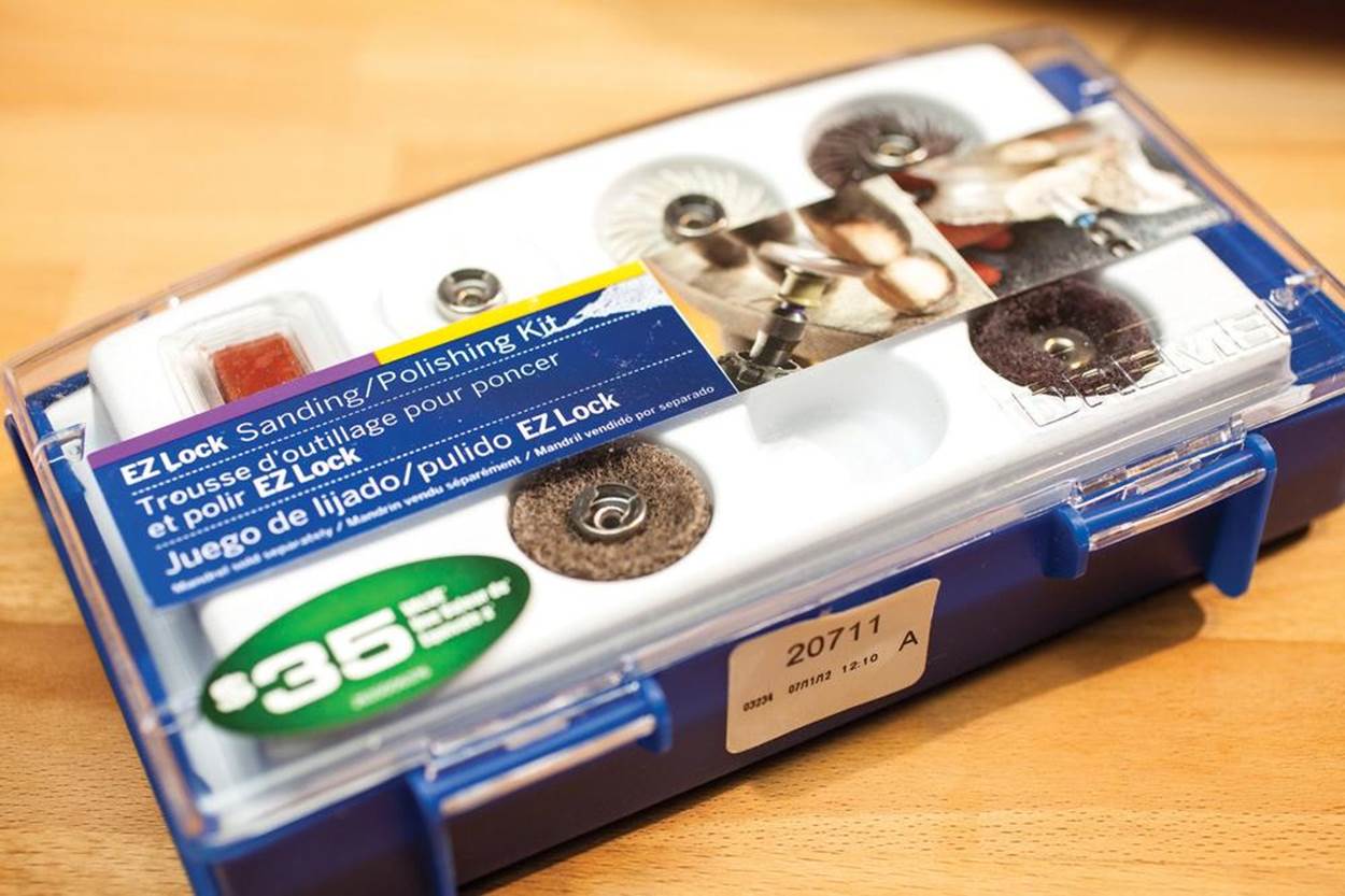
Figure 13-19. Dremel sanding and polishing kit
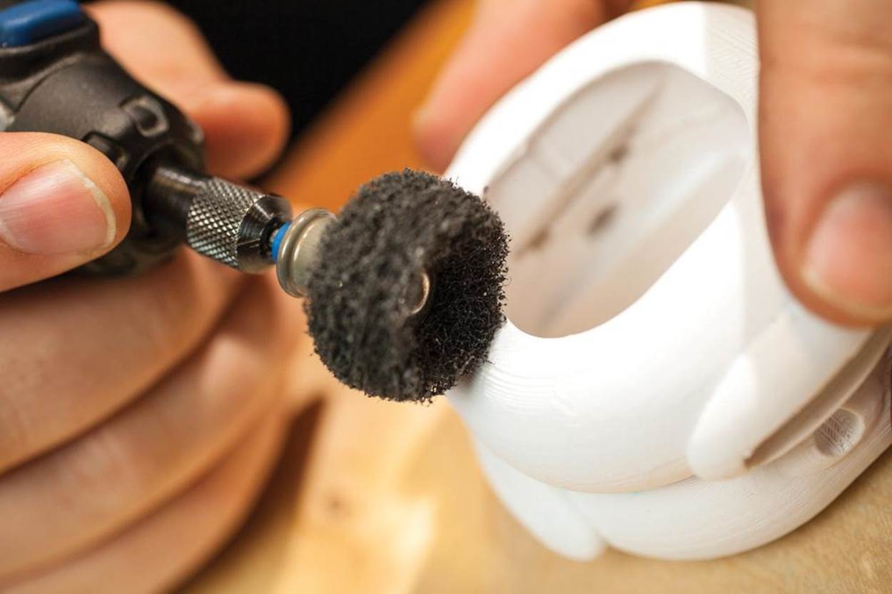
Figure 13-20. Rounding over the peaks
After you’ve sanded a surface to your satisfaction, you can use a heat gun to gently warm the surface (Figure 13-21) until it melts slightly, which will erase many of the smaller scratches and restore the original printed color. Practice on scrap until you get the feel of it.
You can also can use the Novus plastic polishing system to get a remarkably smooth, polished surface on ABS prints, but most 3D modelers opt to just paint their prints instead.
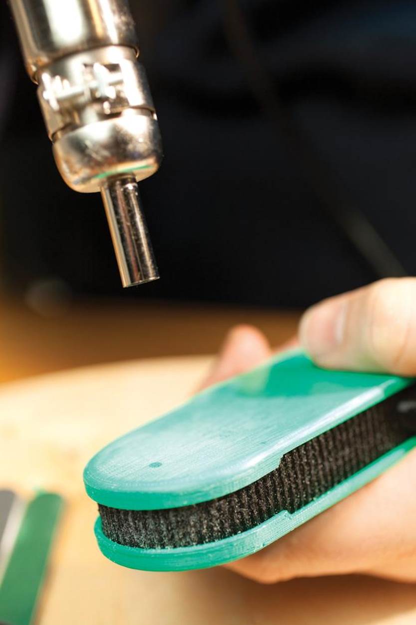
Figure 13-21. Use a heat gun to remove small scratches
Matt Griffin is the Director of Community & Support at Adafruit Industries, a former MakerBot community manager, and author of the forthcoming MAKE book Design and Modeling for 3D Printing.
All materials on the site are licensed Creative Commons Attribution-Sharealike 3.0 Unported CC BY-SA 3.0 & GNU Free Documentation License (GFDL)
If you are the copyright holder of any material contained on our site and intend to remove it, please contact our site administrator for approval.
© 2016-2026 All site design rights belong to S.Y.A.