Make: 3D Printing (2014)
Part II. Software
Chapter 3. Software for 3D Printing
An overview of the necessary design, slicing, and client software.
Matt Mets and Matt Griffin
You’ve got a shiny new 3D printer and a brilliant idea for your first original design—now what?
Creating and printing your own unique 3D models requires three kinds of software. First, there’s the 3D modeling program used to design the shape of your creation. Traditionally, the use of software to prototype physical objects has been referred to as computer-aided design (CAD). Second, there’s the computer-aided manufacturing (CAM) program (commonly referred to as a slicer) that converts your model into specific, mechanical instructions for the printer robot. Third, there’s the printer control software, or client, that sends those instructions to the printer at the right time, and provides a real-time interface to the printer’s functions and settings.
3D Modeling/CAD Software
Probably the most important software choice you’ll make is what kind of modeling program to use. There are many to choose from, but they fall into four basic types: solid, sculpting, parametric, and polygonal. Each type will help you turn your idea into reality, but one may be handier for, say, designing a mechanical part, and another for sculpting an action figure.
Solid modeling programs mainly use a method called constructive solid geometry (CSG), or similar techniques, to define complex 3D shapes. Popular free solid modeling programs include SketchUp, Autodesk 123D, and Tinkercad (which runs entirely in your web browser and is shown in Figure 3-1; read a tutorial in Chapter 4). In a solid modeling program, simple “primitive” shapes like boxes, cylinders, and pyramids are manipulated to make more complex shapes, often using Boolean operations. For instance, a hollow box can be modeled by drawing two overlapping cubes, one slightly smaller than the other, and “subtracting” the smaller from the larger.
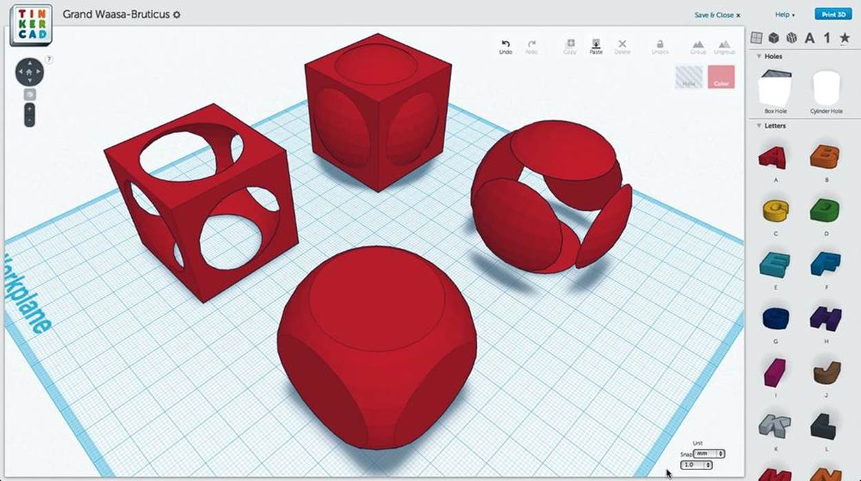
Figure 3-1. Basic Boolean operations illustrated in Tinkercad. From back to front: union, two possible differences, and intersection of concentric cube and sphere.
Solid modeling programs have three big advantages. First, the solid modeling design process tends to be more intuitive than other methods, and is often the easiest way for beginners to get started. Second, the interface usually makes it easy to set precise measurements between objects, which is handy for creating mechanical parts. Third, the software handles most issues of manifold integrity (“water-tightness”) for the user automatically, despite the very large number of operations that may go into shaping a complex form.
Sculpting modeling programs, such as ZBrush, Sculptris, and Mudbox, use a more freeform interface to slice, tug, twist, and press the surface of a “blob” into the desired shape. This makes them great for forming organic surfaces such as faces or figures, but less suitable for precise parts or flat surfaces. A great tool to start with is Sculptris (Figure 3-2), little brother of the more expensive ZBrush. (Many polygonal modeler applications such as Blender, Modo, and Maya are beginning to offer built-in sculpting tools as well.)
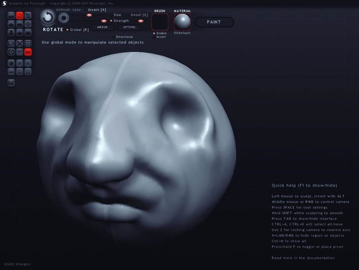
Figure 3-2. Pixologic’s Sculptris allows you to sculpt 3D models like blobs of clay. Tooltips have names like crease, inflate, smooth, pinch, and flatten.
Parametric modeling programs, such as OpenSCAD, are fairly unique; instead of drawing shapes using a mouse, objects are modeled by writing simple programs that describe how to combine different shapes together. Because each dimension can be specified precisely, this kind of tool is great for quickly creating things, such as technical parts like enclosures, gears, and other mechanical objects.
On the other hand, parametric modelers are also useful for producing generative artwork. Tools such as Marius Watz’s ModelBuilder and the Grasshopper editor for Rhino are geared toward generating unexpected, abstract forms by processing other objects or data, or by pure math. Designers like Nervous System use them to create complex organic shapes (Figure 3-3) that would be practically impossible to model by hand (Figure 3-3).
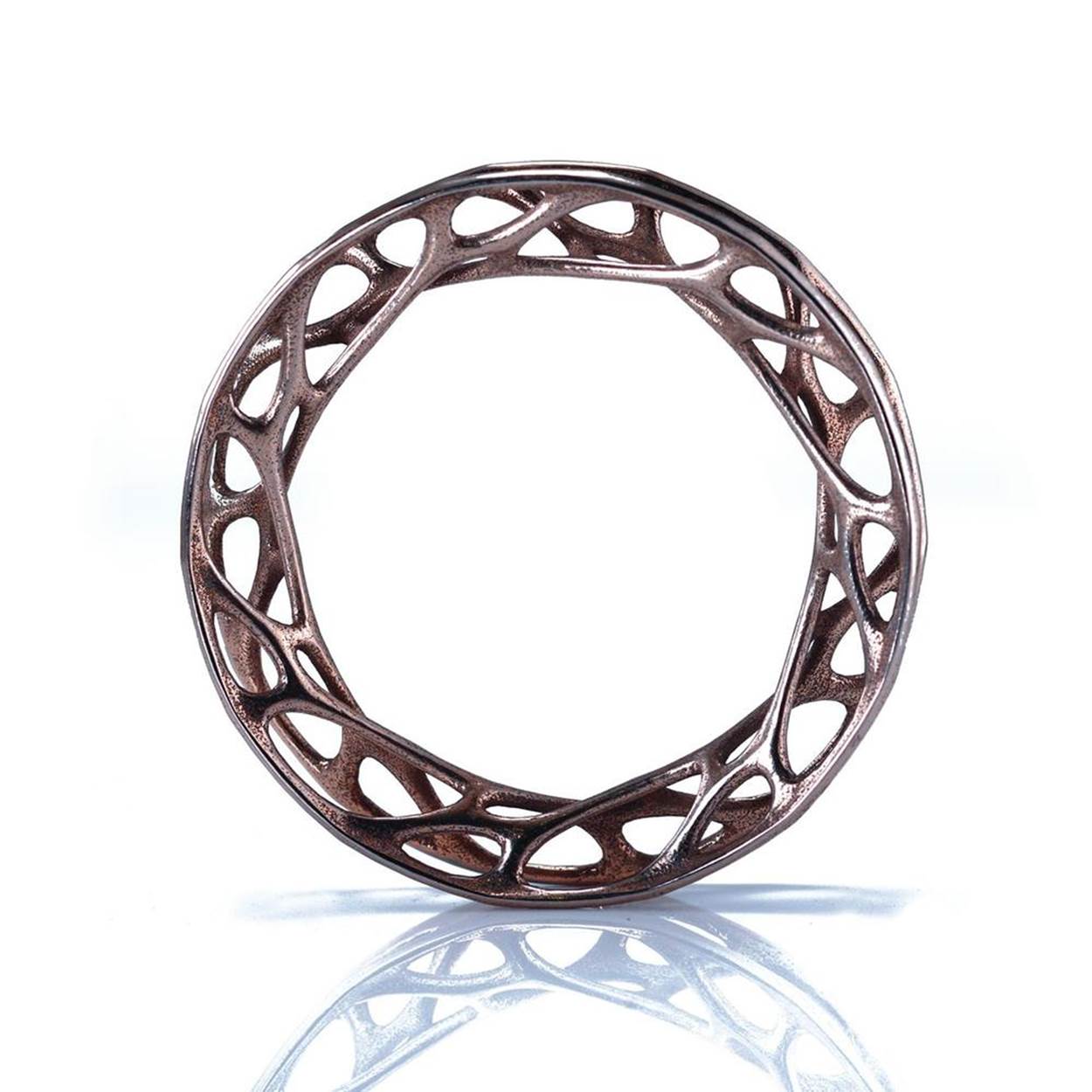
Figure 3-3. Nervous System’s “Convolution” bangle, stainless steel, based on simulated forces in a cellular network.
Polygonal modeling programs represent objects using thousands of tiny triangles arrayed together in a mesh that defines model surfaces. Notable examples include Blender (Figure 3-4), 3ds Max, Maya, and Modo. They’re great for 3D graphics and animation, but require a bit of care when used for 3D printing to make sure that meshes remain manifold or watertight (i.e., without missing polygons or disconnected vertices). If a model is not manifold, the slicer may not be able to tell its inside from its outside and may refuse to process the model at all, or may produce G-code containing serious errors.
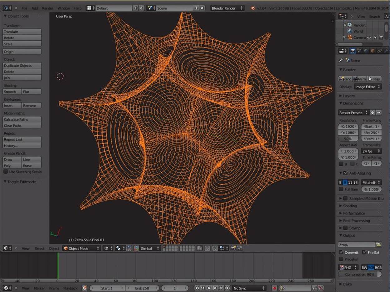
Figure 3-4. Blender is a free, open source polygonal 3D modeling program that is extremely powerful, but challenging to learn.
Polygonal modeling programs offer a tremendous amount of control, but are often challenging to learn. Effective mesh modeling requires mastering a number of sometimes counterintuitive principles like working with “quads” (instead of triangles or “n-gons”), developing “edge-flow” to quickly manipulate models with operations like edge-cutting and loop-cutting, and using “subdivision” tools to automatically smooth jagged surfaces into more organic forms. Extensive tutorials covering these topics in most of the major programs can be found online. Watching a few videos demonstrating best practices early on can save you a lot of trouble as your skills develop.
Your CAD program will produce a 3D model in some file format, commonly STL. Depending on what software was used to produce it and how complex it is, your STL file may contain errors, such as holes or reversed normals, that will need to be corrected before it will print correctly. Your CAM software may detect these errors automatically, and some CAM packages—notably Slic3r—include repair routines that will try to automatically fix simple errors, but you cannot always rely on these to produce reasonable toolpaths. Models can also be repaired manually using a polygonal modeler. Another option is MeshLab, an advanced, open source STL processing and editing tool that is very powerful but may be intimidating to beginners.
One type of modeling program may be handier for, say, designing a mechanical part, and another for sculpting an action figure.
As you become more experienced with 3D printing, you might want to consider investing in a commercial STL analysis and repair tool such as Netfabb Studio. While their Basic suite works well for solving manifold issues quickly and effectively, the Professional version allows you to target specific elements of the model for manipulation, decimation, and re-meshing, as well as offering stable Boolean operations to split up a model into multiple parts. The Professional package also offers built-in slicing utilities and drivers for operating some of the printers directly, in some cases entirely replacing the CAM/client pipeline.
Slicing/CAM Software
Once you have a manifold, error-free 3D model, it must be converted into specific toolpath instructions that tell the printer where to move the hot-end, when to move it, and whether or not to extrude plastic along the way. This process is sometimes referred to asskeining or slicing. The standard format for these instructions is a simple programming language called G-code.
Historically, most printers have relied on the open source Skeinforge engine for preparing G-code from model files. Recently, however, alternative slicing programs have started appearing, most notably Slic3r, which has been slowly overtaking Skeinforge as the tool of choice. For more on how to use Slic3r, see Chapter 5.
A fairly recent closed-source utility called KISSlicer, available in free and pro versions, boasts some unique features, such as adaptive sparse infill (using more material near the edges of a print and less in the center) and multi-extruder support (using different material for separate models, support structures, and infill).
Though most slicing engines can be run as standalone programs, they’re commonly built into integrated printer client packages like ReplicatorG (Figure 3-5) and Pronterface, so that the same interface used to control the printer can also be used to load and slice 3D models directly.
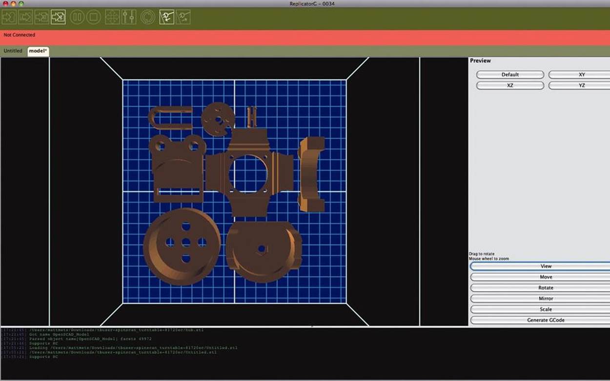
Figure 3-5. Laying out a build plate in ReplicatorG. All of these parts will print simultaneously.
Note that because a 3D print proceeds layer by layer, the G-code to print a single copy of a model is very different from the G-code to print, say, four copies side by side. If you want to print multiple parts per job, one option is to simply lay out build plates, as they’re called, directly in your 3D modeling program. Another option, which many find more convenient, is to lay out build plates at the CAM level. Many slicing engines, as well as integrated print environments like ReplicatorG, now provide tools that allow easy scaling, repositioning, and duplicating of CAD models before slicing. These usually include a virtual environment that shows how everything will fit into the printer’s build chamber.
The slicing program will provide an interface to adjust a number of variables related to print speed and quality, such as layer height, maximum print-head speed, infill density, number of “shells” surrounding the infill in each layer, and whether or not to print support structures or “rafts.” Many slicing engines have built-in profiles to get you started, and most work well right out of the box. Eventually, you’ll probably want to experiment with these settings to suit specific geometry or design challenges.
A handy practice when getting familiar with slicer settings is to use a G-code visualizer to preview the print. A visualizer will display the G-code commands as a series of lines to represent the print-head toolpaths. Scrolling through the layers can help you learn how the slicing software tackles the geometry of the original object, and will reveal errors without using up any plastic. Saving a series of G-code “drafts” of a figure before actually running a print job is a great way to gauge the effect of adjustments to the various slicer settings. If you’re using ReplicatorG, grab Pleasant 3D (for Mac, shown in Figure 3-6) or GCode Viewer for Blender (cross-platform). Both Pronterface and Repetier-Host have built-in G-code viewing utilities.
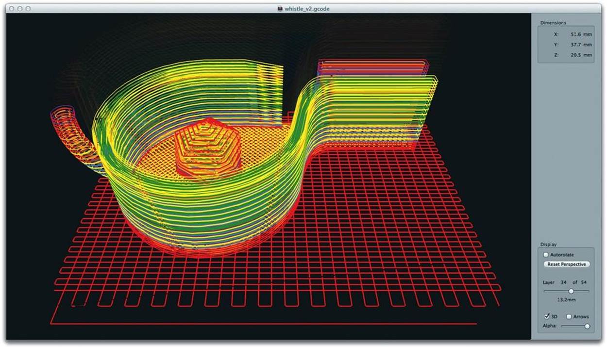
Figure 3-6. Visualizing G-code in Pleasant3D. The interface allows you to scroll through the toolpaths one layer at a time.
Printer Control/Client Software
Finally, there’s the client, which is basically the printer’s real-time control panel. It provides a software interface where you can start, stop, or pause the printing process at will, as well as set the temperature of the extruder nozzle and the bed heater, if present. The client will usually provide a set of directional buttons that allow you to incrementally move the print head in any direction, which can be useful for bed leveling, calibration, and manual zeroing.
Historically, many machines relied on ReplicatorG for machine control. Recently, though, some alternatives have appeared, and the amount of innovation is impressive. The Printrun suite (featuring Pronterface) and Repetier-Host are the most actively developed and used. Ultimaker has been developing the open source Cura package which is feature-packed and easy to use. Some closed-source printers, such as PP3DP’s Up and MakerBot, ship with custom client software that will usually include a similar set of features.
In use, the essential function of the client is to send toolpath instructions to the printer over a WiFi or USB connection. Many printers are designed for operation in “untethered” mode, in which the printer runs on its own without a computer connection. In untethered mode, no client program is necessary; the printer automatically reads and follows CAM instructions from an SD card or USB thumb drive plugged into it directly. Untethered printing can be useful, for instance, for long-running prints during which you may want to use your computer elsewhere, or if you have more printers than computers to run them. CAM information is usually stored on removable media as G-code instructions. For a rundown of all the available printer control and slicing software, see 3D Printer Frontends andSlicing Software.
What Next?
Your printed object will inspire improvements and new ideas. The design pipeline is really a cycle.
Now that you’ve got the basic workflow down, you’re ready to make anything! Remember that 3D design and printing is an iterative process, and that things rarely turn out perfectly the first time around. If you aren’t comfortable with any of the tools that you tried, be sure to look at others—there’s no reason to limit yourself to only one workflow. Experiment, tweak, observe, repeat! Try to learn something from each mistake, and always remember to have fun.
Matt Mets is a maker who uses electronics to create playful objects that teach and inspire.
Matt Griffin is the Director of Community & Support at Adafruit Industries, a former MakerBot Community Manager, and author of the forthcoming MAKE book Design and Modeling for 3D Printing.
All materials on the site are licensed Creative Commons Attribution-Sharealike 3.0 Unported CC BY-SA 3.0 & GNU Free Documentation License (GFDL)
If you are the copyright holder of any material contained on our site and intend to remove it, please contact our site administrator for approval.
© 2016-2026 All site design rights belong to S.Y.A.