Make: 3D Printing (2014)
Part II. Software
Chapter 4. 3D Design for the Complete Beginner
Use Tinkercad to design a robot-head pencil topper in minutes.
Blake Maloof
Three-dimensional printing offers exciting applications, from art to product design to rolling your own replacement parts. But if you’re new to this technology, the modeling software and printer hardware can be intimidating. The learning curve is steep as you go from concept to 3D model to printed object. If only you could create a simple design on your desktop, have it printed on a high-end 3D printer, and delivered to your door. Turns out, you can!
Tinkercad is an intuitive, browser-based CAD modeling application that allows you to quickly box out your design and hit a Print button to send it off to 3D printing services like Shapeways or Sculpteo. You can go from concept to ready-to-print 3D model in minutes with little to no modeling experience.
To get you started and to show just how easy it is to make something fun and unique, I’ll walk you through the process for creating a robot-head pencil topper. All you need is a computer with an Internet connection.
UNDERSTANDING POSITIVE AND NEGATIVE SPACE
To utilize Tinkercad to its full potential you need to understand the concepts of positive and negative space. For example, you can place a box, which represents a solid, positive shape, and you can also place a hole, a negative shape. Holes remove any solid material within their shape.
This will become very important when you submit your model for printing. Because the cost depends on the solid volume of the print, you’ll want to make the object as hollow as you can.
1. Create a Tinkercad Account
Create a Tinkercad account. Then click the “Design a New Thing” button. Tinkercad will give your new thing a name; change it by clicking the gear icon.
2. Make a Hole
To make the hole that your pencil will fit into, measure the width and height of a pencil eraser. It’s about 8 mm at the widest point, so click and drag a cylinder onto the Tinkercad “workplane” (the blue grid) and scale it to 10 mm diameter. This will provide 1 mm of wiggle room all around the pencil. To scale something in Tinkercad, first select it by clicking on it, then click on one of the small white rectangles situated around the object—these are called handles—and drag it.
To scale the shape uniformly in all directions, hold the Shift key while dragging.
The height of the eraser is about 20 mm, so stretch the cylinder to 20 mm using the top handle. Don’t use the Shift key here because you want to stretch only the height, not the diameter.
Now, with the cylinder selected, click the Hole icon (next to Color in the upper-right corner of the workplane window). This will turn the cylinder into negative space, indicated by gray stripes (see Figure 4-1).
If you make a mistake, use the Undo button or type Ctrl-Z (Cmd-Z on a Mac) to undo the step.
It’s often useful to view your design from a different angle. To do this, click on the arrow buttons in the upper-left corner of the window. The + and – buttons are for zooming and unzooming.
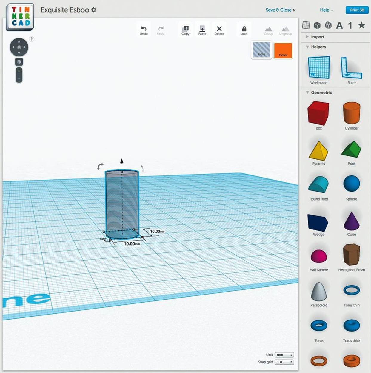
Figure 4-1. A negative space object
3. Make the Robot Head
Make a box for the robot head. You can make it any size, as long as the width and depth will encompass the negative cylinder with at least 1–2 mm on each side. I made a head that was 34 mm wide × 24 mm deep × 24 mm high, and placed it alongside the hole (Figure 4-2).
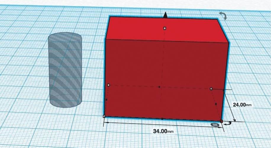
Figure 4-2. Make the robot head
4. Align the Head and the Hole
To make sure the hole is in the center of the box, use the handy Align tool. Select both the box and the hole cylinder by Shift-clicking each object, or click-dragging your cursor to create a Select box around them, or using Ctrl-A (Cmd-A on a Mac) on your keyboard to select everything. Look for the small gray circle with three white lines next to your selection. Click it and select Align.
Tinkercad will highlight both objects with alignment dots. Click the two middle dots on the horizontal plane to position the hole in the center of the box (Figure 4-3). Don’t center the hole on the vertical axis because that would seal the hole entirely inside the box, which would make it impossible to fit a pencil in the bottom.
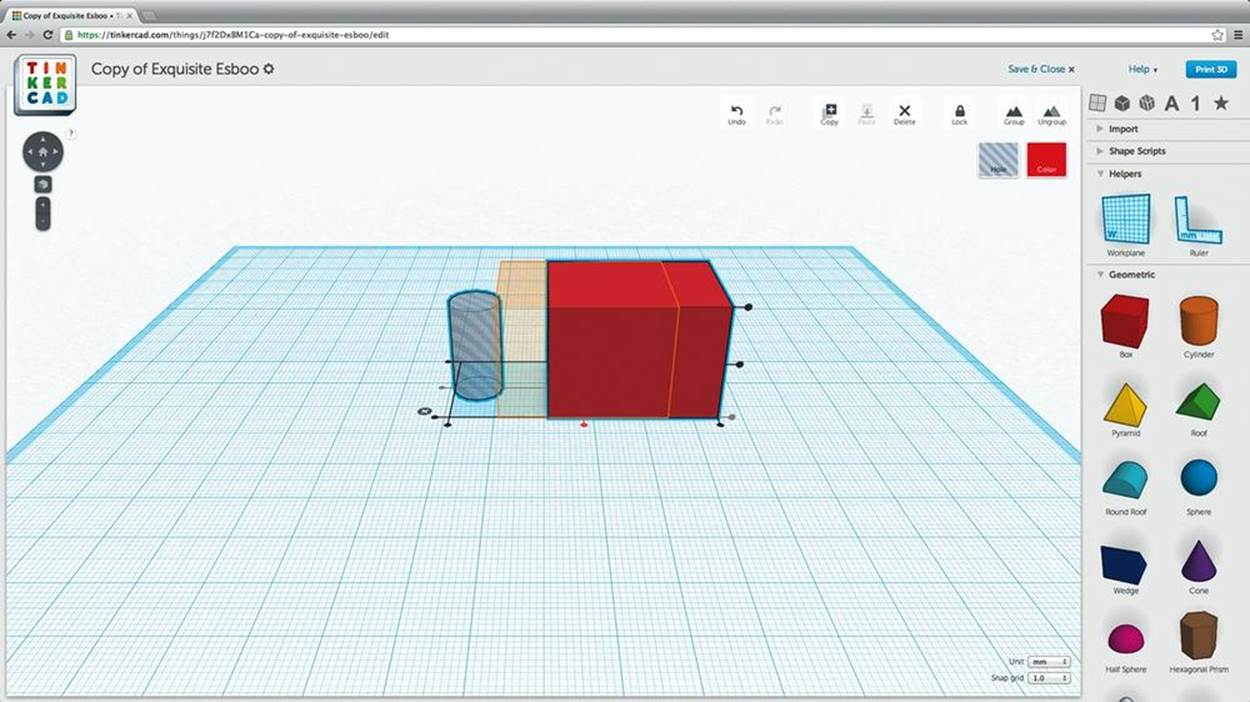
Figure 4-3. Align the head and the hole
5. Combine the Head and Hole into a Single Object
Select both pieces and combine them into a single object by clicking the Group icon (Figure 4-4).
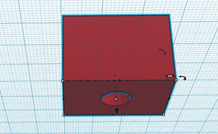
Figure 4-4. Combine into a single object
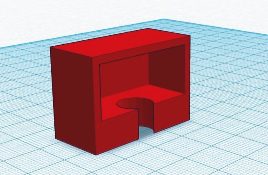
6. Make the Head Hollow
Make a hole box to put inside the robot’s head. Size it 4 mm smaller than the head in both width and depth. This will leave the head with 2 mm-thick walls.
We don’t want the inside to be completely hollow, as we need material at the bottom to hold the pencil in place. So, leave about 10 mm of material at the base by making your hole box 10 mm shorter than the head. In my case, the interior hole is 30 mm wide × 20 mm deep × 14 mm high (Figure 4-5).
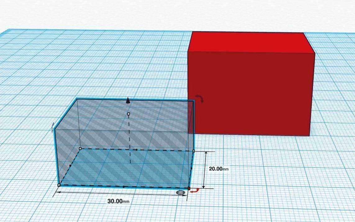
Figure 4-5. Create an interior hole
Use the Align tool to align the hole box to the top of the robot head, by selecting the topmost vertical dot (Figure 4-6). Now select just the hole box and use the arrow handle to move it down 2 mm (Figure 4-7).
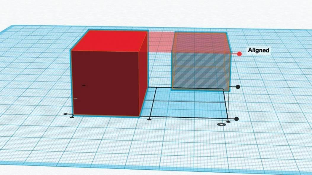
Figure 4-6. Select the topmost vertical dot
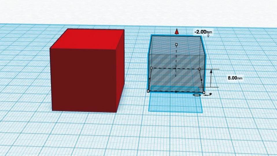
Figure 4-7. Select the hole box and use the arrow handle to move it down 2 mm
Select the hole box and the head box again, and align them on the horizontal plane (but again, don’t click the vertical align buttons or else the hole box will move to the top or bottom of the head box).
Select all the pieces and combine them into a single object by clicking the Group icon. You now have a nice 2 mm border on the top and sides of your hollow robot head.
By default, the workspace has a grid snap size of 1 mm, so when adjusting the space between two objects, you can use the arrow keys to move the selected shape in 1 mm increments.
Notice that a selected shape casts a shadow on the blue gridded plan of your workspace. Use this shadow to help you place your pieces into their proper locations.
7. Make Your Robot’s Mouth
Start by making a mouthpiece with a box that’s smaller than the robot’s head.
To create the speaker-grill ridges, make a series of even smaller hole boxes. You can make one and create copies by clicking the Copy button; using copy-paste keyboard commands; or clicking on the original, holding the Option key, and dragging off a clone. Space them evenly apart and slide them into the mouth box (Figure 4-8).
Then, with only the hole boxes and the mouth box selected, click Group. This will apply the hole objects to the box, cutting out the negative shapes, and turning them into holes (Figure 4-9).
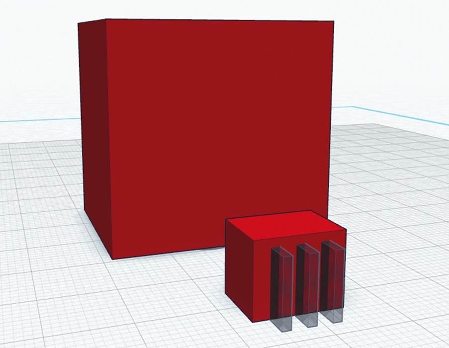
Figure 4-8. Construct the mouth ridges
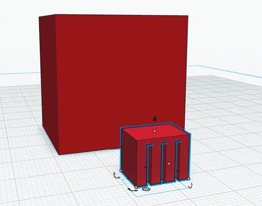
Figure 4-9. Create the mouth ridge holes
Place the mouthpiece so it sticks out from the front and bottom of the head box. (Don’t push it in so deep that it intersects the pencil hole.) Group the head and the mouthpiece (Figure 4-10).
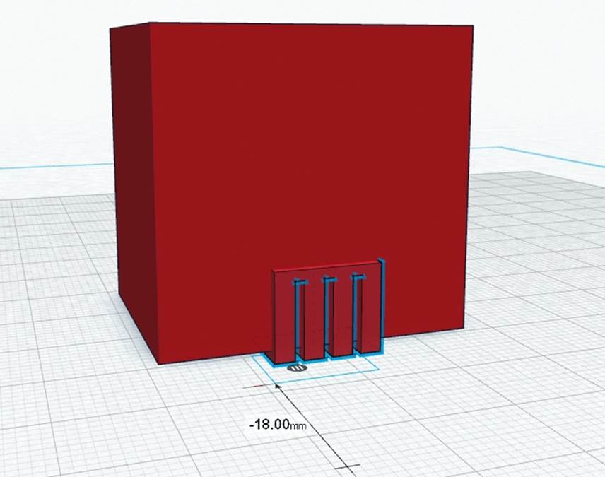
Figure 4-10. Group the head and the mouthpiece
X-RAY VISION
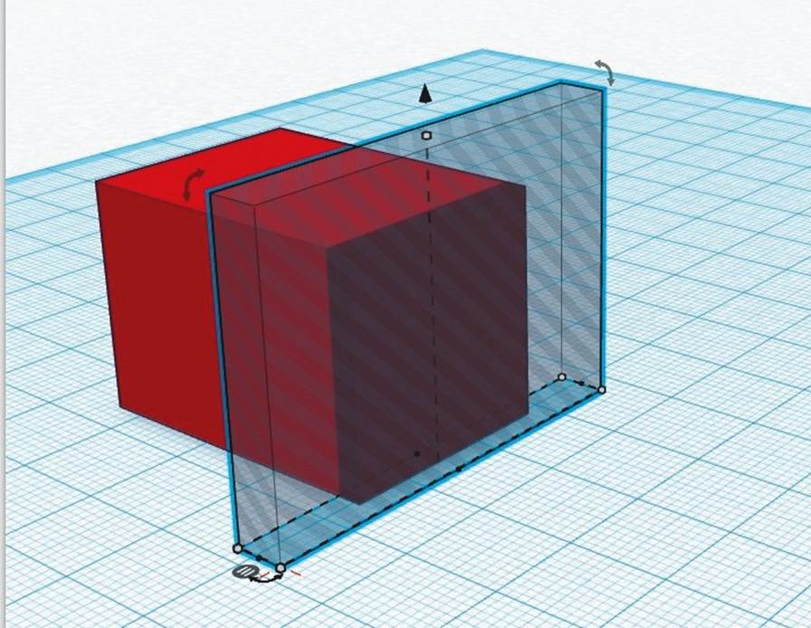
How can you verify that the hole box is positioned correctly inside the head? Here’s a little hack that provides a clearer view inside your work.
Drag a box onto the workplane, turn it into a hole, and change its dimensions until it’s larger than one side of your design. Move the hole box so that it intersects your design, select all the objects, then click Group. Voilà! An interior view. Now, just Undo your way back to where you left off.
8. Make Your Robot’s Eyes
To make the eyes, drag two cylinders into the workspace and make them holes. See those curved arrows next to the cylinder? Click and drag them to rotate the cylinder into the proper orientation (Figures 4-11 and 4-12).
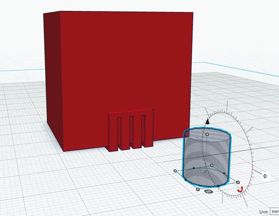
Figure 4-11. Get a cylinder
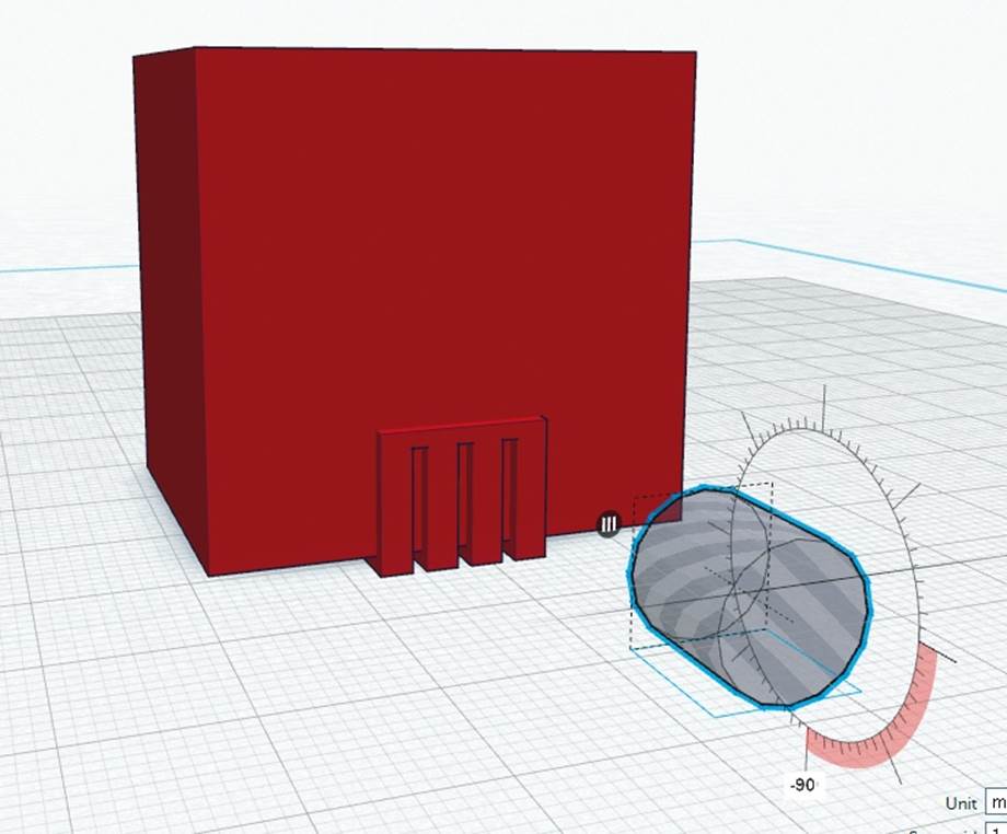
Figure 4-12. Position it into the proper orientation for eyes
You need to raise the cylinders above the workplane grid so you can place them above the robot’s mouth. Use the black arrow handle above the cylinder to do this. Make the cylinders different sizes to add a little personality. Be sure the cylinders intersect with the head by 1 mm. Select the cylinders and the head and Group them (Figures 4-13, 4-14, and 4-15).
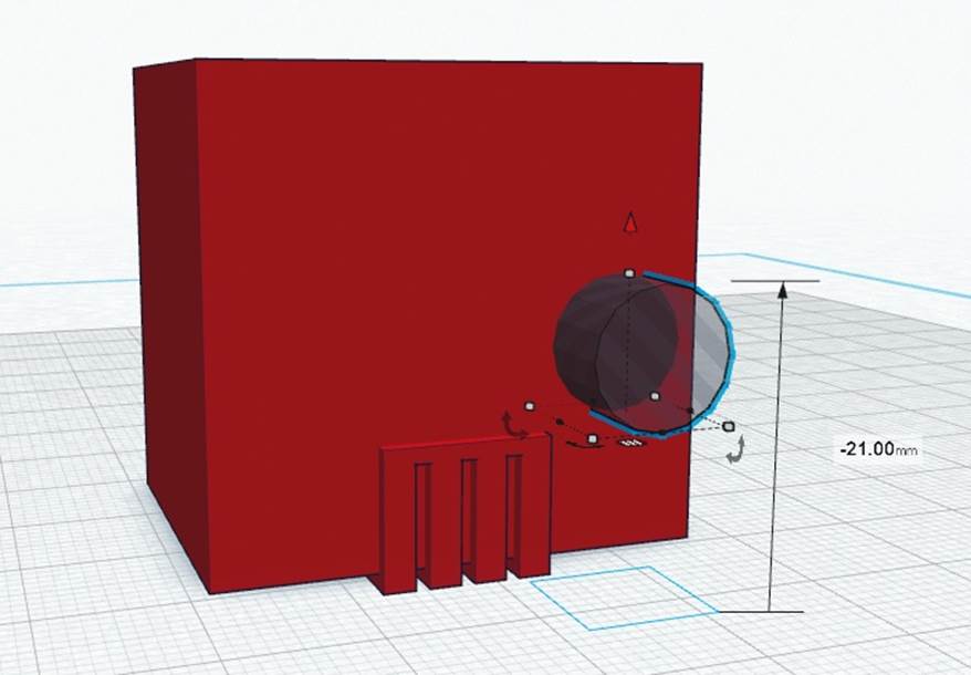
Figure 4-13. Intersect the cylinder with the head by 1 mm
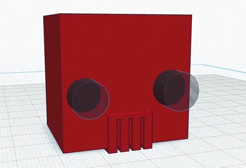
Figure 4-14. Select and group cylinders
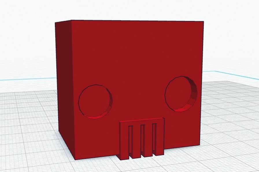
Figure 4-15. Completed print-ready robot head pencil topper
Tada! You now have a print-ready robot-head pencil topper (Figure 4-16). Just hit the Print 3D button, select a printing service, and order yourself a new toy that you designed!
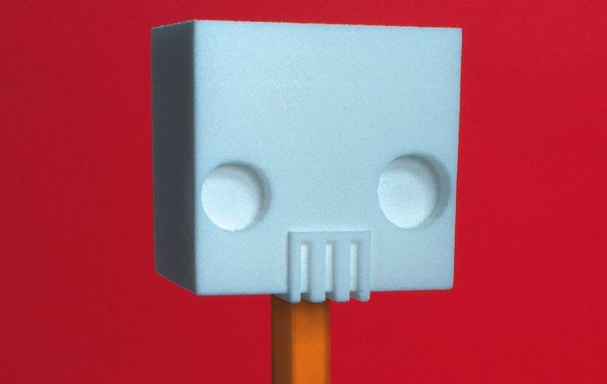
Figure 4-16. Finished!
Check out the 3D model here.
Blake Maloof is a game designer at Toys for Bob (makers of Skylanders), and he sometimes writes about games for MAKE.
All materials on the site are licensed Creative Commons Attribution-Sharealike 3.0 Unported CC BY-SA 3.0 & GNU Free Documentation License (GFDL)
If you are the copyright holder of any material contained on our site and intend to remove it, please contact our site administrator for approval.
© 2016-2026 All site design rights belong to S.Y.A.