Make: 3D Printing (2014)
Part II. Software
Chapter 5. Getting Started with Slic3r
Slic3r is a free program that prepares STL files for printing.
Eric Weinhoffer
So you have a 3D printer and a 3D file, but now what? Well, you have to slice it up into layers and create a G-code file, which you’ll then send to your 3D printer. There are many software options for slicing 3D models in preparation for 3D printing including: Slic3r, KISSlicer, CuraEngine, MakerBot Slicer, and Skeinforge. (See Slicing Software for more on each of these options). Some of these “slicers” are integrated into printer control software and some, like Slic3r and KISSlicer can be used independently of control software.
Slic3r has become a popular option because it’s open source, cross-platform, free to use, relatively quick, and extremely customizable.
I’ll describe how each of the many settings relates to the actions of your 3D printer, and how to correctly adjust them to optimize your machine for your application. I don’t have experience with tweaking all of these settings (there are a lot), but I’ll do my best to describe what they do.
I recently read RichRap’s fantastic guide, “Slic3r is Nicer”, and I recommend that you give it a read as well. Although Rich has a lot of nice photos and great explanations in his tutorial, it is almost a year old, and a lot has been added to Slic3r since then. Unlike me, he does cover extruder calibration in his tutorial, which is an optional, although beneficial, process.
The manufacturer of your 3D printer will most likely provide you with some default slicing settings: hopefully as an exported .ini file that you can import, but they might instead give you a list of numbers that you have to manually enter into Slic3r. If they supplied a .iniprofile file, I’d recommend starting with that and tweaking settings from there (you can import a profile in Slic3r by going to File→Import Config).
Despite the fact that I provide good starter settings here, there is no set formula that will work well for all machines, so experimentation is required if you really want to optimize your prints.
You can download Slic3r for free from the Slic3r website. Now open it up and let’s get started!
Unless otherwise noted, photos of prints in progress are from John Abella.
Step 1: Name Your Profile
The application is broken up into four tabs: Plater, Print Settings, Filament Settings, and Printer Settings. The Plater tab is the most self-explanatory, and typically the last place you’ll end up before slicing, so we’ll come back to that later.
One of the neat things about Slic3r is how easy it is to create, and recall, a bunch of different profiles (Figure 5-1).
After changing any setting, clicking the Save icon will bring up a text box, where you can change the name of the profile (Figure 5-2).
Try creating a profile not only for each separate printer, but for each specific type of print as well, like “Ultimaker Hollow Part” or “Ultimaker Super Fast.”
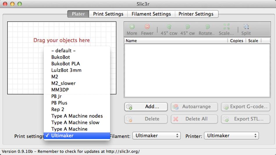
Figure 5-1. Picking a saved profile
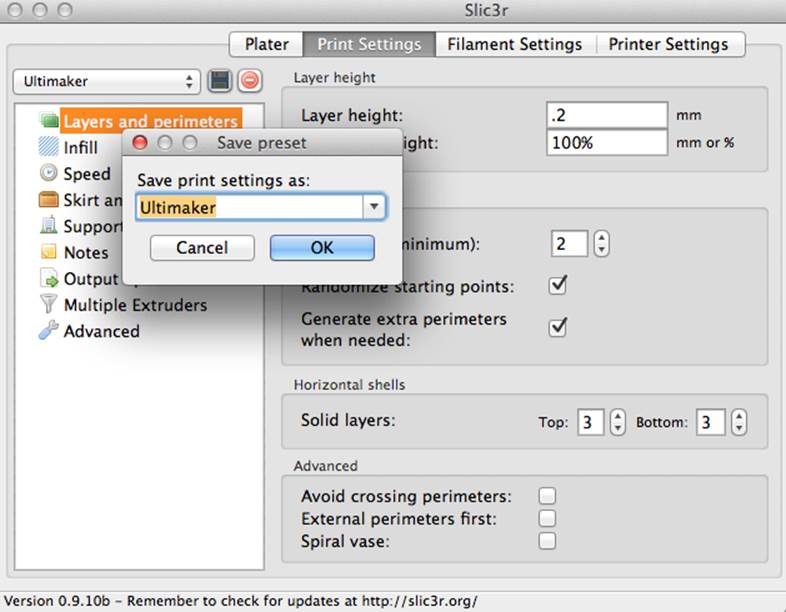
Figure 5-2. Saving a profile
Step 2: Print Settings
The first subset of Print Settings is “layers and perimeters.” The layer height (Figure 5-3) is the distance the z-platform (or extruder) moves between each layer. A smaller layer height will generally result in a better looking, smoother part, but it will also take longer to print. Anywhere between 0.2 and 0.3 mm is probably a good place to start.
Many machines on the market today will handle a layer height of 100 microns (0.1 mm) without a problem.
A print with a layer height 0.1 mm will have twice as many layers as a print with a 0.2 mm layer height, and will therefore take twice as long to slice and print.
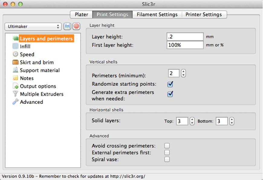
Figure 5-3. Setting the layer height
The first layer height specifies the height to use for the first layer you print. It can be entered in mm or % (a first layer height of 200% will be twice the standard layer height). You can use a thicker first layer to make sure your print has a stronger base for all successive layers.
Perimeters and Solid Layers
Perimeters (or shells) are also important (Figure 5-4) in that they add to the strength of your print. A perimeter value of two specifies that the printer will draw two solid outlines around the edge of the part it’s printing, on every layer (Figure 5-5). I’ve found that two is usually a good place to start, but three-perimeter prints are common as well.
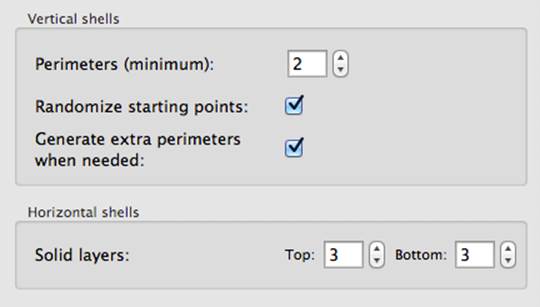
Figure 5-4. Setting perimeters
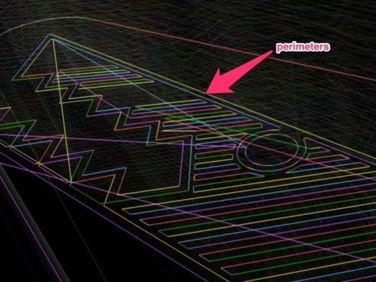
Figure 5-5. The effect of perimeters
Randomizing the starting point of perimeters will prevent a visual indentation from appearing on the side of your part, so I’d recommend keeping that box checked. Allowing Slic3r to generate extra perimeters when needed is also a good idea.
Solid layers are completely filled in with plastic (Figure 5-6), which is why it’s usually smart to have a few of them on the bottom and top of your part. I’d recommend doing at least two solid layers on the bottom, and stick with at least one on the top.

Figure 5-6. Solid layers
Keep in mind that if you’re printing a very large part, each solid layer will take up a good chunk of time, so dial those values down if you value print time over part strength.
Infill
Fill density (Figure 5-7) is the percentage of each layer that will be filled in with plastic (0.2 = 20%). You shouldn’t have to go above 60% for any reason, unless you want a really dense part. A 20% fill is just fine for your everyday prints, but adjust at will and play with the parts once they’re complete to feel the difference in structural stability.
A density of 0 will only print the perimeter(s) of your part, so it will be completely hollow.
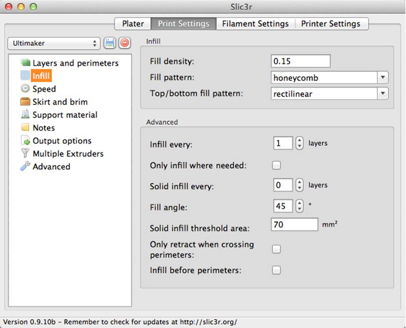
Figure 5-7. Setting fill options
The fill pattern (Figure 5-8) is the path that the extruder takes when doing the infill. These don’t have a huge impact on the structural stability of the part. The “Top/bottom fill pattern” is the pattern used on the top and bottom solid layers.
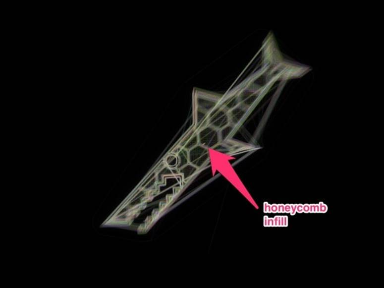
Figure 5-8. The fill pattern inside an object
The advanced settings give you even more control over the infill, although I don’t think I’ve ever touched them. “Infill every 2 layers” will alternate between layers of filled (with the fill density you chose) and hollow. “Infill every 3 layers” will have two hollow layers between every filled layer, etc. I’ve always left this at 1, the default.
You can also choose to insert a solid layer every n layers, for extra stability. The fill angle is the angle at which the extruder will do its filling paths, based on the orientation of the axes in your machine. I don’t see how changing this will affect your part very much, but it may have varying levels of impact based on the fill patterns you use.
I typically leave “Only retract when crossing perimeters” unchecked. We’ll learn about retraction soon, and then this will make sense.
Speed
Now on to speed (Figure 5-9)! Perimeter speed determines how fast the perimeters will be printed. 50 mm/s is a good place to start, but check your printer’s documentation because some printers can go much faster while others must have this value set lower. The small perimeter speed is how fast small features will be printed. This is typically slower than your normal perimeter speed, to give the plastic more time to cool down.
External perimeters are the outer perimeters of your part—the most important ones. I’d start with a speed similar to, if not exactly the same as the standard perimeter speed, and go from there.
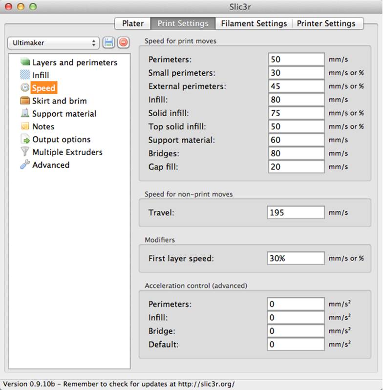
Figure 5-9. Setting speed
Infill speed is how fast your machine will print during the infill stage. Since clean lines and extreme accuracy aren’t paramount here, crank it up! The speed I’m using here, 80 mm/s, is quite conservative, especially for the Ultimaker, but it’s probably a good place to start.
Solid infill speed determines how fast the solid infill layers will be printed. These paths are more important than your everyday infills, so keep this slower than your standard infill speed. Don’t bring the speed down too much, however, since 100% infill layers take a while.
The top solid infill speed is how fast the top, 100% filled layer(s) will be printed. Since it’s important that these look nice, keep this speed lower than your two other infill speeds.
Bridges are used to fill in a gap, where the extruder stretches filament between two walls over air. If the gap’s any greater than around 0.5”, you’re going to get drooping, no matter how fast you move, but moving quickly will prevent anything major. Printing material and nozzle temperature will have an effect on plastic droop during bridging. Travel speed is the speed at which your machine will move between two extrusion points. Since you’ll never be extruding at this time, you might as well crank up the speed here as well. I’d recommend starting at 175 mm/s and moving up from there. Machines that use a light Bowden extruder (like the Ultimaker) can move as quickly as 300 mm/s.
First layer speed will modify how quickly your machine prints the first layer. I’d start with 50% and go from there. Read the second part of Rich’s tutorial on getting your first layer to stick.
The Skirt
The skirt (Figure 5-10) is an outline around the perimeter of your part, drawn by your printer before it does anything else. This is a great opportunity to “prime” your extruder, make sure your nozzle’s at a good height, and kill the print before it gets too far if any adjustments are needed.
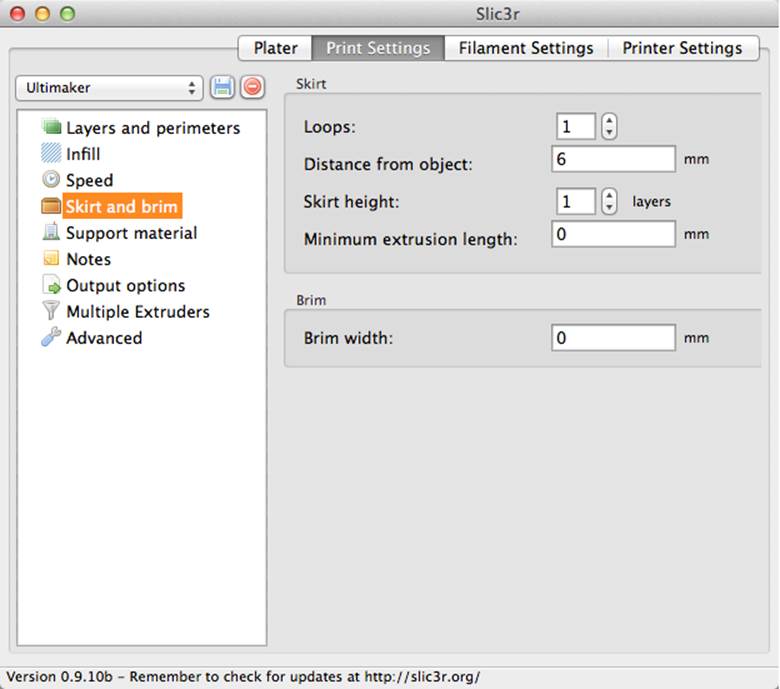
Figure 5-10. Configuring the skirt
If your extruder typically takes a few seconds before the plastic appears, increase the number of loops so it will make its way around your part more than once. Typically, the skirt is kept at one layer high, and anywhere from 3 to 10 mm away from the object (seeFigure 5-11).
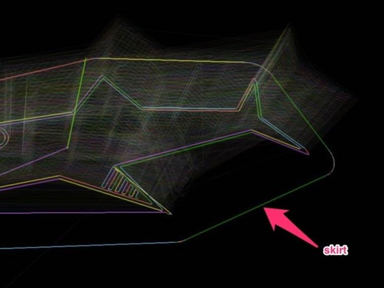
Figure 5-11. The skirt
Support Material
Automatically generating support material (Figure 5-12) during slicing will cause your printer to print scaffolding under overhangs and tough angles, giving you better overall results once the support’s pulled away. Just check that box (Figure 5-13), and Slic3r will do all the tough work for you.
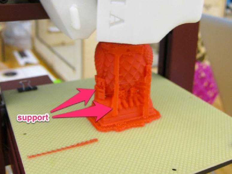
Figure 5-12. Support material
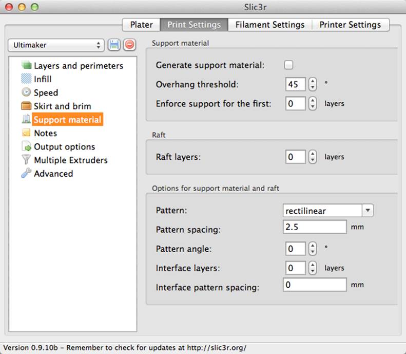
Figure 5-13. Configuring support material
The overhang threshold is the angle past which support will be generated. To prevent the machine from generating support for tiny protrusions that really don’t need it, start with 45 degrees.
You can also select a pattern of support, just like you did with the infill, but it’s probably more important here, since certain patterns are easier to break away post-print than others. Rectilinear is a good place to start.
The pattern spacing will also have a major effect on the structure of the support—a higher value will generate support that’s easier to break away. The pattern angle is the angle at which the support will be printed, with respect to the x- and y-axes of your machine.
Too low of a pattern spacing will yield support that’s more similar to the rest of the part, and will be hard to break away. But, too high of a pattern spacing may not provide enough support for the overhangs.
Notes and Miscellaneous Settings
Notes (Figure 5-14) are useful for your own records; they are completely optional and have no effect on the print. After printing a part and noticing how your changes affected the output, type your notes in here so you know what to change in the future.
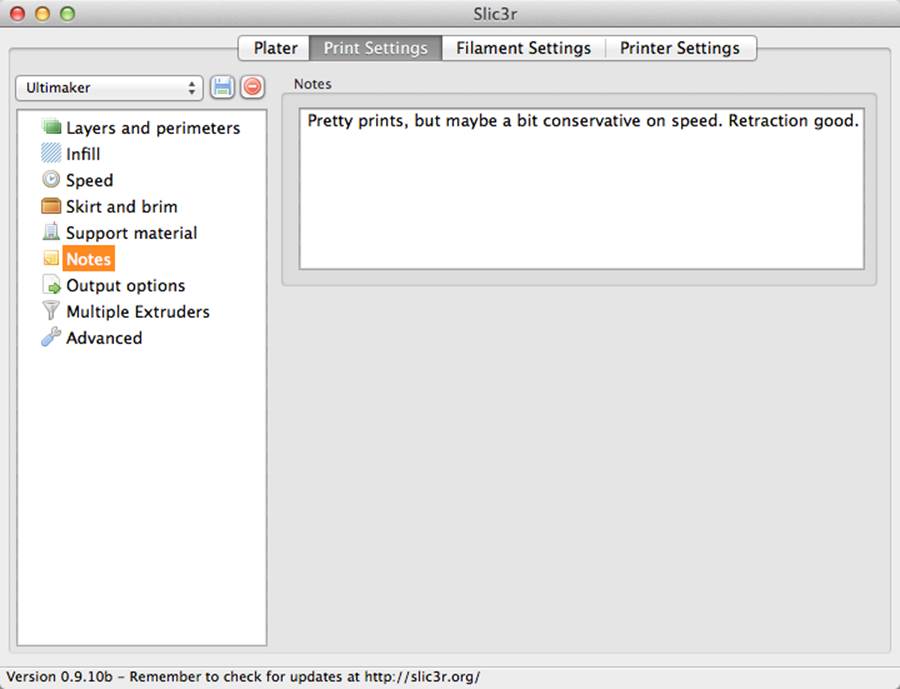
Figure 5-14. Taking notes
You’ll only need to mess with sequential printing if you have an automated way to remove parts from the print bed and want to print many parts in sequence. I’ve never bothered with changing the output options (Figure 5-15), but they’re useful if you’d like to create a standard format for G-code filenames, for example.
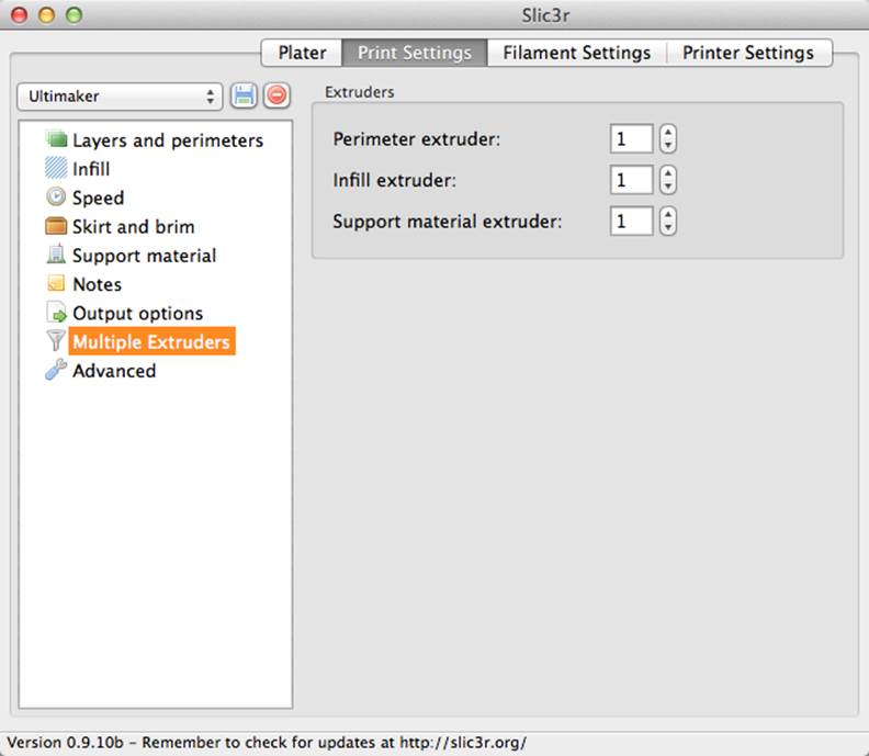
Figure 5-15. Output options
The multiple extruders settings (Figure 5-16) are designed for machines with just that—more than one extruder. Here you can specify specific tasks for each extruder, like support and infill.
Figure 5-16. Configuring multiple extruders
Advanced Settings
I haven’t messed with any of the advanced settings (Figure 5-17) except for the extrusion width. With accurate plastic and nozzle information (which you’ll enter later), Slic3r can adjust the height of the extruder to widen the width of extrusion.
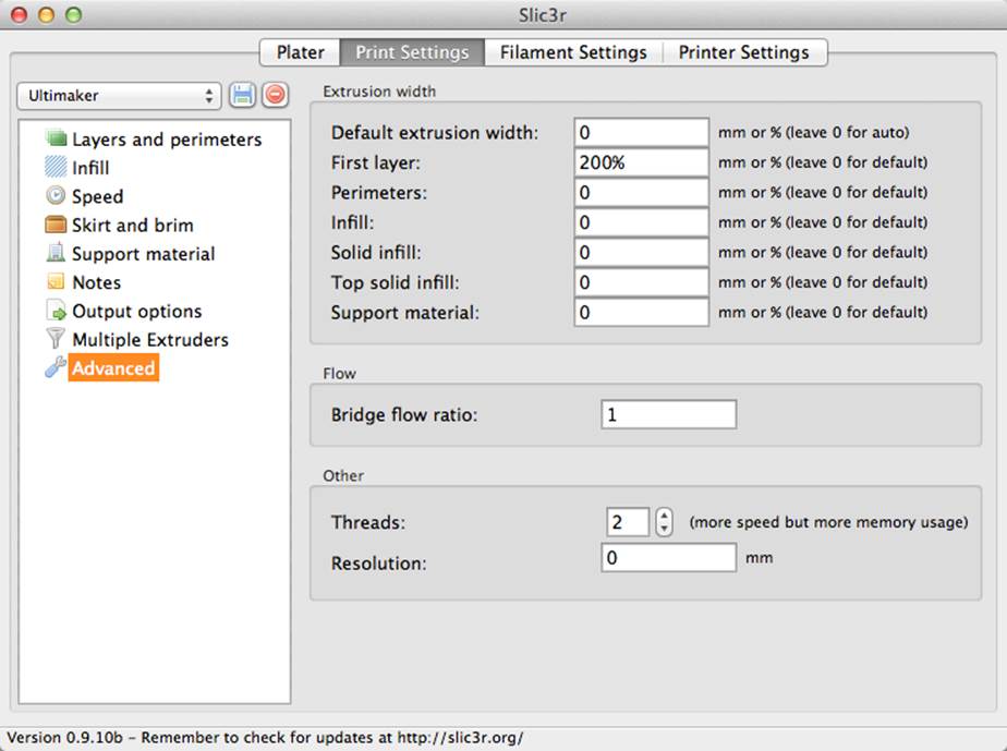
Figure 5-17. Advanced settings
You may want to bump the first layer width up past 100% in order to get the plastic to stick to the bed more efficiently, but I’ve never felt the need to adjust the other widths.
Step 3: Filament Settings
Now we’re moving on to the next main tab, Filament Settings (Figure 5-18). Your machine probably came with some plastic, or you may have bought some other spools in different colors or materials. Your filament is probably advertised as being 3 mm or 1.75 mm in diameter, but that’s never quite right.
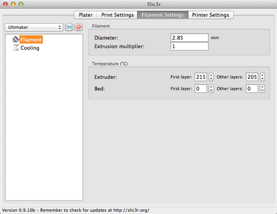
Figure 5-18. Filament settings
So, take a caliper or micrometer to your filament at a few different positions, and average your readings (Figure 5-19). Input the average into Slic3r.
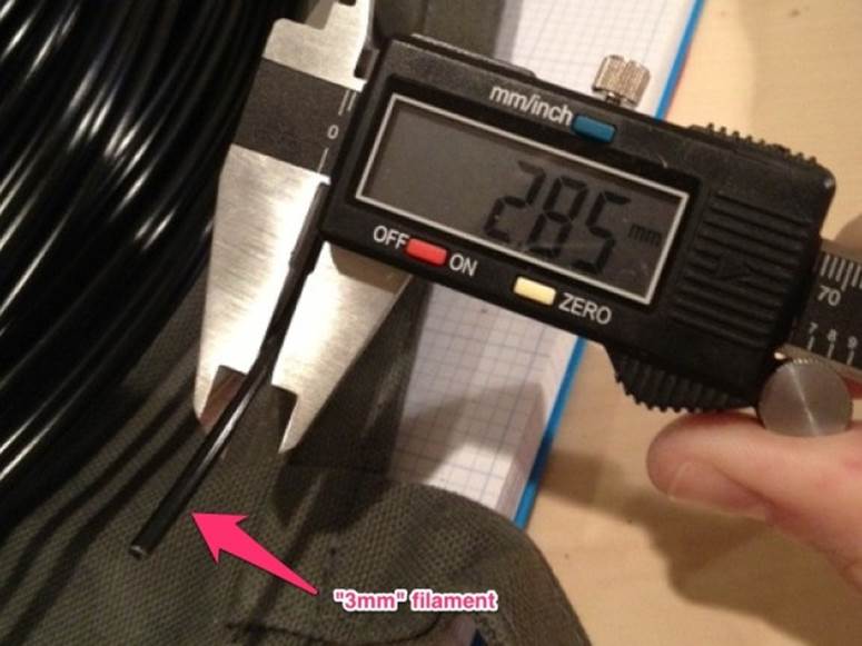
Figure 5-19. Caliper measurement
The extrusion multiplier will simply alter the value you just entered into the diameter box. Unless you have a specific reason to do so, leave this at 1.
Extruder and bed temperature are also very important. You can specify a different temperature for the first layer. If anything, run your extruder hotter than usual to start, to promote extra gooeyness and stickiness.
For PLA, an extruder temperature of 185 is probably as low as you want to go (this Ultimaker profile is set for PLA printing). For ABS, I’d recommend starting at 220.
If you have a heated bed, use it at whatever temperature you feel comfortable with, since anything will help. For PLA, 60 is probably a good place to start, and 110 is good for ABS (although if your bed takes forever to get that hot, dial it down so you won’t have to wait hours for a print to start).
If you don’t have a heated bed, keep the bed temperature at 0. If it isn’t at 0, the print will never start.
Cooling
Next up is the cooling settings page (Figure 5-20). Start with the fan settings. If your machine doesn’t have a fan directed at the extruder or build platform (Figure 5-21), you can skip this step. If you have a fan, check “Enable auto cooling” and read the description that pops up when you hover your mouse over it—this setting will intelligently cool only when needed, and keep the fan off at all other times.
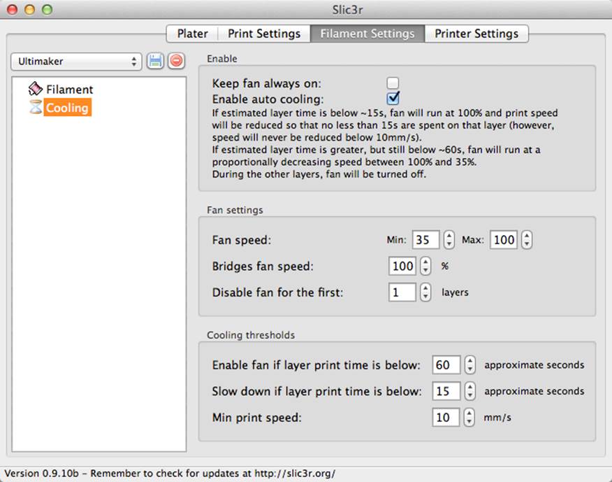
Figure 5-20. Cooling settings
As you adjust the following settings, refer back to the description under the enable auto cooling box to see how your edits will change the intelligent cooling activity of the machine during printing.
Fan speed is a percentage and is really up to you. Do a few prints with cooling enabled and increase the minimum fan speed if you notice that your plastic is drooping or excessively sticking to the nozzle. Bridges fan speed is how fast the fan will turn during bridging—keep this high to promote cooling and minimize drooping.
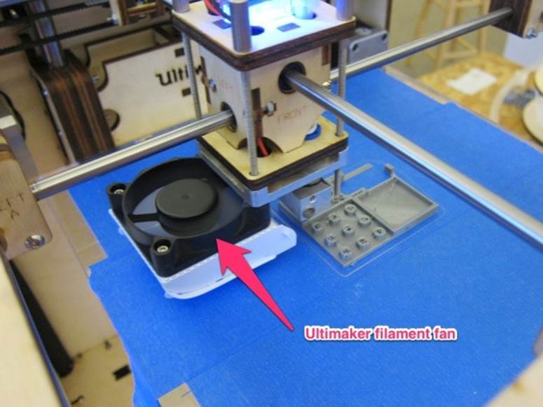
Figure 5-21. The Ultimaker fan
I like to disable the fan for the first layer to keep the plastic as gooey and liquid as possible, to keep it stuck to the bed (this is especially popular with PLA printing). You can also check a box to keep the fan on at all times, from print start to end.
The cooling thresholds give you more advanced control over when the fan starts. In general, layers with shorter print times (such as the tip of a cone) are more difficult for the printer to complete successfully, and therefore benefit most from additional airflow.
The thresholds to set for decreased printing speed will come with time and lots of experimentation, but I think these are a good starting point:
|
Enable fan if layer print time is below |
60 seconds |
|
Slow down if layer print time is below |
15 seconds |
|
Min print speed |
10 mm/sec |
You can set the minimum print speed fairly low; this will result in a great variation in print speed during more challenging prints.
You may find that separate cooling thresholds are necessary for different parts, so creating a different slicing profile for each may be the quickest solution—for example, one for objects with lots of narrow columns, and one for hollow objects, one for busts (where detail is important).
Step 4: Printer Settings
Now we can move onto the Printer Settings tab (Figure 5-22). Before we start with general settings, break out the ruler. Measure the usable length and width of your print area, and enter the results into the bed size boxes. The print center should be half of the bed length and width, so that the print starts at the exact center of the build platform.
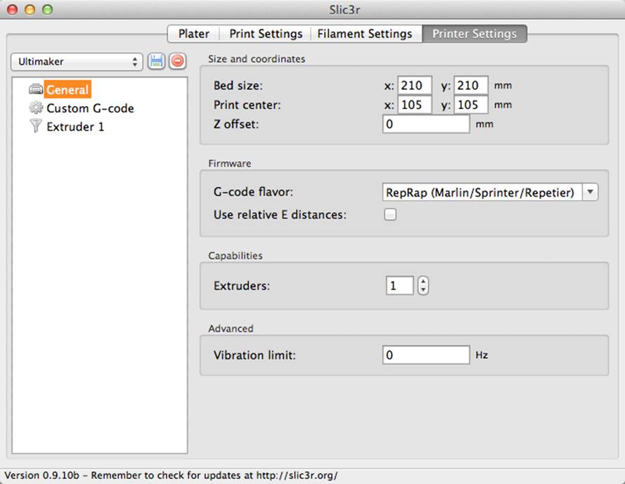
Figure 5-22. Printer settings
The Z offset is set at 0 mm by default, and should be left there unless you frequently change to a build platform of a different thickness. If, for example, your heated glass platform is removable, you can set the Z offset to its thickness so your machine will automatically adjust for it when you slice a part with that profile.
The G-code flavor should be fine at RepRap (Marlin/Sprinter), but definitely take a look at the drop-down and select the one that most accurately describes your machine.
Leave the “Use relative E distances” box unchecked unless you’re absolutely sure that your machine uses relative positioning. Most use absolute positioning, which specifies the end point of the current move in the G-code, regardless of where you are.
The extruders value should only be changed from 1 if you have more than one extruder on your machine. If so, go back to the Multiple Extruders section of the Print Settings tab and mess with those settings.
Custom G-Code
Custom G-code (Figure 5-23) can be used to override the default calibration settings (steps per mm) and position the extruder at a specific point at the start of a print, among other things.
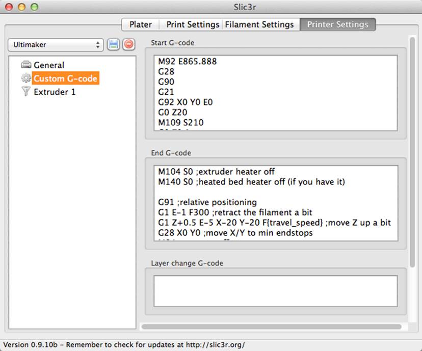
Figure 5-23. Custom G-code settings
The custom G-code will nearly always be specific to your model of machine, so you should check the manufacturer’s documentation for these settings.
The start G-code often includes commands to zero out all three axes, heat up the extruder and heated bed, do some sort of test extrusion, and start the print.
The end G-code typically turns off the extruder and heated bed, zeros out all three axes again, and lowers the z platform for easy part removal.
Extruder Settings
Now on to the Extruder 1 section of the Printer Settings tab (Figure 5-24). The nozzle diameter should be provided by your manufacturer, but if not, take a pair of digital calipers to it and measure it yourself. It will most likely be 0.35, 0.4, or 0.5 mm.
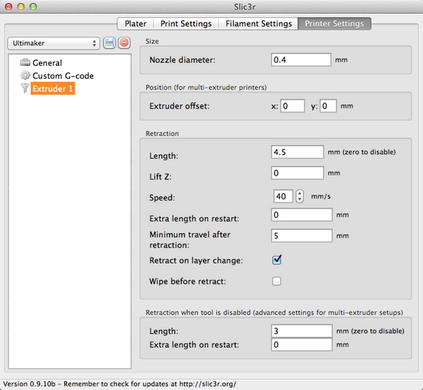
Figure 5-24. Extruder settings
Don’t bother with extruder offset unless you have more than one extruder. If you do, this is the horizontal and vertical distance between your extruders.
Since there’s so much to talk about when it comes to retraction, I’m devoting the whole next step to it.
Retraction
Retraction (Figure 5-25) is one of the coolest features in Slic3r, and will greatly improve the quality of your prints. By retracting the hot filament with the extruder motor during travel moves, plastic oozing is prevented. The length of filament to retract before moving to the next extrusion path will depend wildly on the motor and gearing you have.
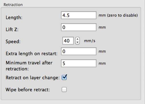
Figure 5-25. Retraction settings
If you have no idea what to put here, I’d recommend starting with 0.75mm and moving up from there if you notice that you’re still getting stringing between gaps. The value I’m using here is so high because of the Ultimaker’s extruder gearing.
Lift Z will raise the extruder (or lower the bed) during retraction and before moving to the next path, where it will lower, in order to avoid knocking the part off the platform or dragging plastic with it. If you’re building tall parts that may get knocked off the platform easily, set this to one layer height. If not, I would leave this at 0.
Speed is how quickly your extruder motor will reverse to retract the filament. You want this to be quick, so do some tests with your extruder and see just how fast you can retract. I’d recommend starting at 15 mm/s and building up from there, since once again, extruders will differ wildly in gearing and motor speed.
Extra length on restart is the length of plastic you’d like to extrude after traveling to a new path and prior to moving again. I don’t use it, since it would just put extra plastic down where I don’t necessarily need it. The only application for this may be when your extruder has serious problems starting up again after retraction, but in that case I’d just recommend dialing down your retraction length and/or speed instead of setting this to anything other than zero.
Minimum travel after retraction is the minimum distance required for the printer to retract at all between paths. If you specify 3 mm, for example, if the two paths are closer than 3 mm the extruder won’t retract, to prevent the motor from doing tons of unnecessary work during an extremely complicated print. I think 2 mm is a good place to start.
The last two settings here are for multi-extruder setups. When one of the extruders is disabled, you can have it retract to prevent it from oozing while the other one is working. You can also add extra length on restart here, where it may have more use, since extruders in a multi setup are often idle for longer and may require additional priming.
Step 5: Return to the Plater
Now we can finally move back to the Plater tab! Load a part by clicking Add, or dragging it into the grid on the left. The part will automatically snap to the center of your build platform (Figure 5-26).
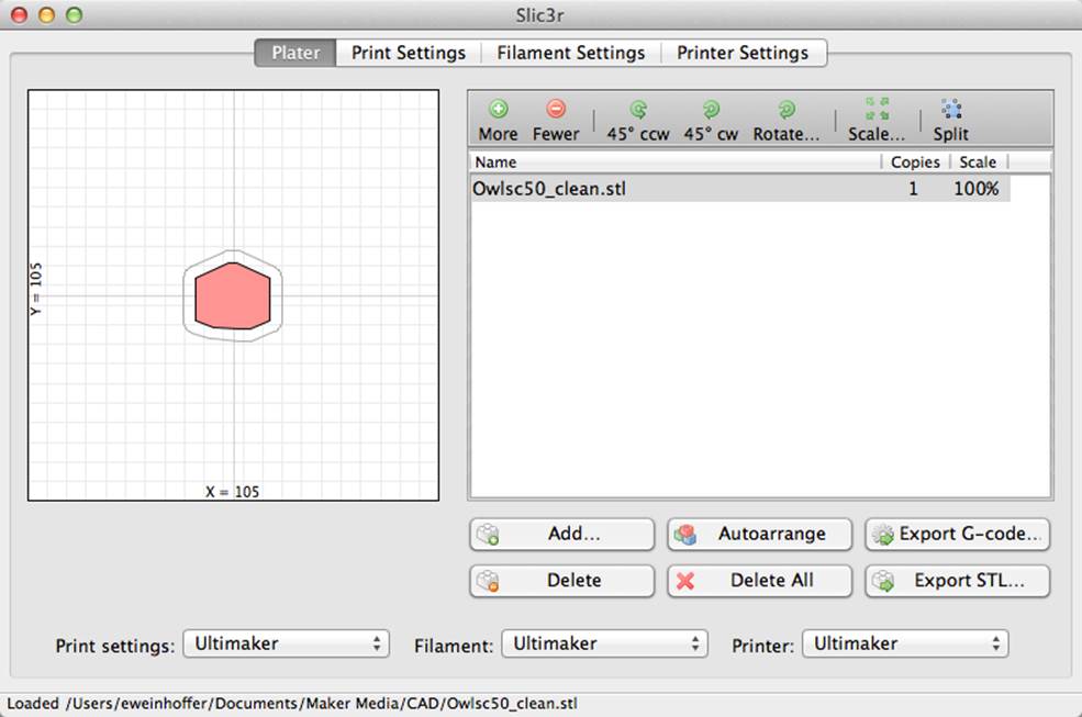
Figure 5-26. Centered item on the plater
You can add additional parts in the same manner, and then duplicate them by clicking “More” after selecting them (selected parts will be red). They’ll be automatically arranged as you add them onto the plate (Figure 5-27).
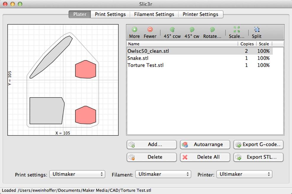
Figure 5-27. Adding multiple parts
You can also rotate the parts with the 45° ccw (counterclockwise), 45° cw (clockwise), and Rotate buttons. Clicking Rotate will bring up a text box (Figure 5-28) into which you can enter a specific angle. You can also scale an object with the Scale button.
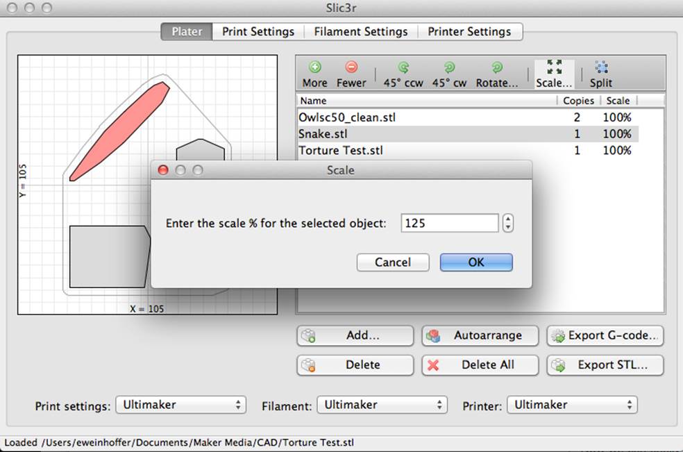
Figure 5-28. Rotating Parts
Working with Multiple STLs
If you import an assembly of multiple STLs, you can split it up into its separate STLs with the Split button. See Figures 5-29 and 5-30.
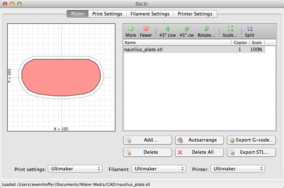
Figure 5-29. Nautilus plate before splitting
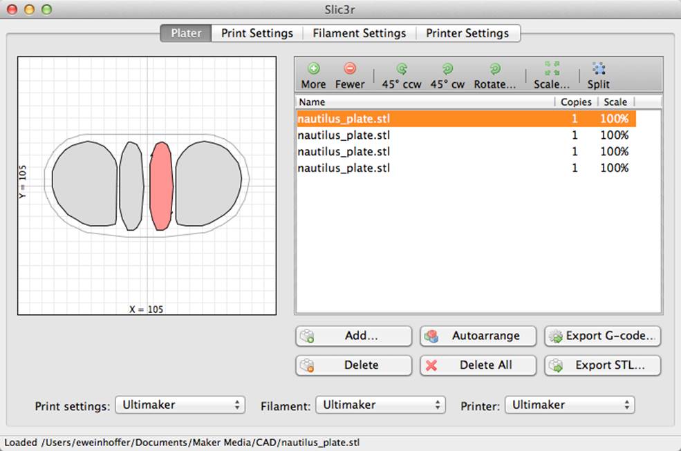
Figure 5-30. After splitting STLs
This is useful if you needed to print a few extra gears, but also wanted to print one single piece of another part (Figure 5-31).
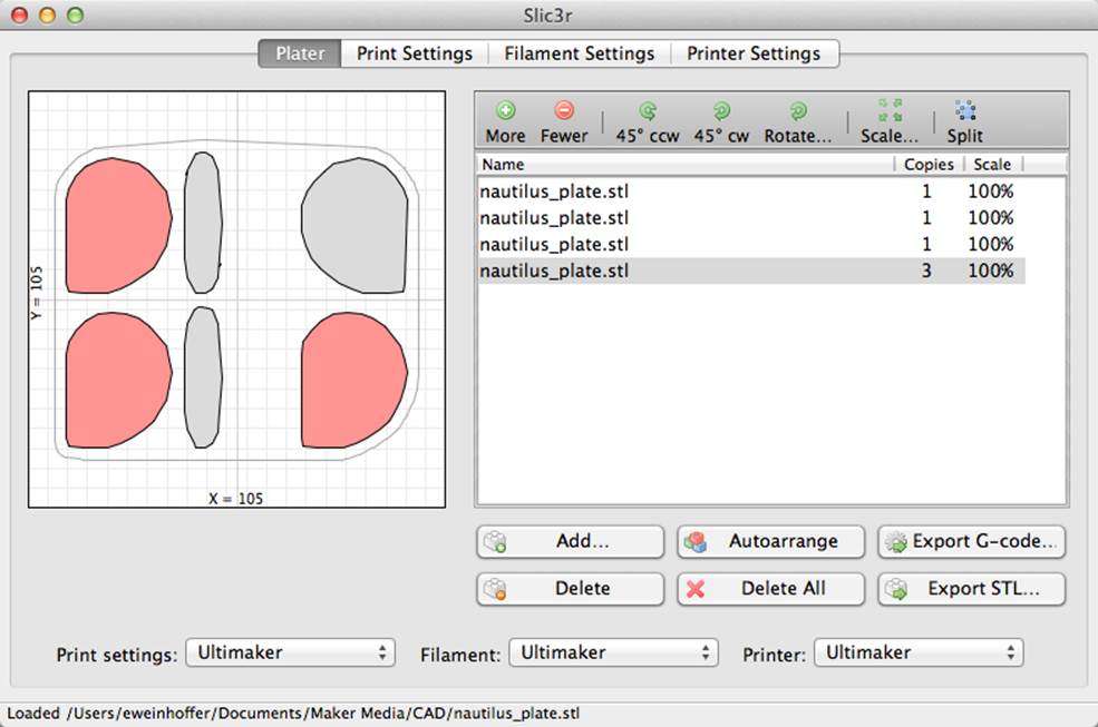
Figure 5-31. Split STLs
Have Fun!
That’s it! Enjoy using Slic3r.
The free in-browser G-code viewer used for a few of the photos is by Jeremy Herrman: GCode Viewer.
Eric Weinhoffer is a Product Development Engineer at MAKE. He creates kits and sources products that we sell in the Maker Shed. Occasionally he writes about cool things for the blog and magazine.
All materials on the site are licensed Creative Commons Attribution-Sharealike 3.0 Unported CC BY-SA 3.0 & GNU Free Documentation License (GFDL)
If you are the copyright holder of any material contained on our site and intend to remove it, please contact our site administrator for approval.
© 2016-2026 All site design rights belong to S.Y.A.