Canon EOS 70D: The Guide to Understanding and Using Your Camera (2014)
Chapter 9. The Shoot2 Menu

Shoot2

Figure 9-1. The Menu display with the Shoot2 tab selected
Lens Aberration Correction
When there’s a comma in the price of a lens (that is, anything over $999), you have good reason to expect superior quality. Nonetheless, the laws of physics limit just how far glass can be ground, and in what manner multiple lens elements can be combined, while still having an affordable and mobile assembly to mount on the front of a camera. Fortunately, there’s another branch of science—mathematics—that can be applied to in-camera image processing to assist in compensating for some of these residual shortcomings.
Canon creates correction profiles for several of their best lenses and makes that data available to register in the EOS 70D. Canon has also preloaded the correction data for 27 lenses into the camera. If you’ve enabled either or both of the Lens Aberration options, the EOS 70D will automatically determine which lens is mounted. If correction data has been registered for that lens, then that correction data will be applied to the captured image before the image is recorded to the memory card (once the image is recorded to the memory card, you cannot apply this aberration correction feature). You can use the EOS Utility software to delete from the camera any aberration-correction data for lenses that you do not have or to register aberration correction data for one or more lenses you have acquired. The EOS 70D can register aberration-correction data for as many as 40 lenses.
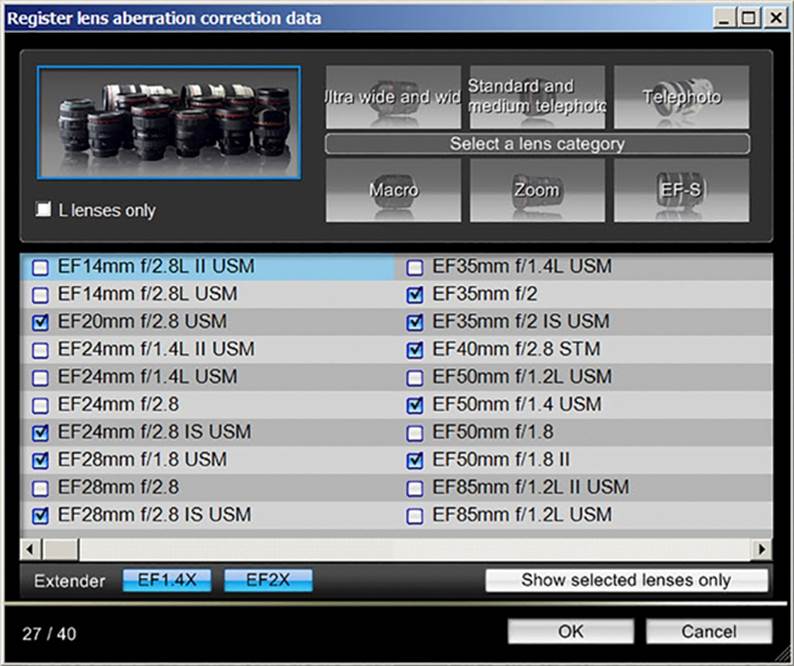
Figure 9-2. The list of registered lenses for the EOS 70D
Peripheral illumination is the term used to describe the phenomenon in which the corners of the image seem dark. This is a common problem that many lenses experience to some degree, but the problem becomes especially obvious when using large apertures. Peripheral illumination is similar to a vignetting problem, but is a result of lens design, and can be overcome by allowing the camera to automatically apply Peripheral Illumination correction if it’s available for the lens you are using.
Chromatic Aberration is a phenomenon that is aggravated by digital image capture, and becomes most evident in well-lit exposures with strong contrast. The result is something called color fringing. In the pair of photos in Figure 9-5, notice the edge of the building’s roof. In the left picture, you will see a translucent purple tinge at the junction of the roof and the sky (ah, yes, well lit with strong contrast). The right image was taken with the very same setup, except Chromatic Aberration correction was enabled.
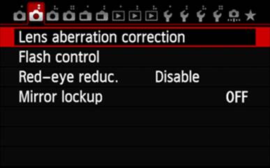
Figure 9-3. The Shoot2 menu’s Lens Aberration option
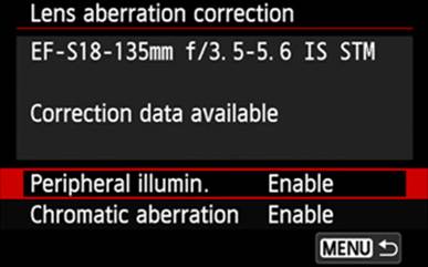
Figure 9-4. Enabling Peripheral Illumination correction for a registered lens
By default, the Peripheral Illumination and Chromatic Aberration options are both enabled. If you wish to disable either or both, or to re-enable them after they have been disabled:
1. Press the MENU button.
2. Use the touch feature or the Main Dial to select the Shoot2 menu.
3. Use touch, the Quick Control Dial, or the Multi-controller to select the Lens Aberration correction option.
4. If you used either the Quick Control Dial or the Multi-controller for option selection, press the SET button.
5. Use touch, the Quick Control Dial, or the Multi-controller to select the parameter you wish to change.
6. If you used either the Quick Control Dial or the Multi-controller for parameter selection, press the SET button.
7. Use touch, the Quick Control Dial, or the Multi-controller to select either Enable or Disable.
8. If you used either the Quick Control Dial or the Multi-controller for selection of the value, press the Menu button.
9. If you wish to change the other setting, repeat steps 5 through 8.
10. Press the MENU button or touch the MENU icon on the LCD Monitor to return to the Shoot2 menu.

Figure 9-5. Color fringing eliminated by in-camera Chromatic Aberration correction
Flash Control
The EOS 70D has a built-in (internal) electronic flash, which can work either alone or in conjunction with auxiliary lighting coming from external sources. Electronic flash units are the external light sources employed by the majority of DSLR users. Canon designs, builds, sells, and supports a line of electronic flash units under the name Speedlite. These units represent a broad spectrum of power and capabilities.
The internal flash is also referred to as a Speedlite.
Flash Firing
The EOS 70D can provide additional illumination through the internal flash, a flash-only hot shoe-mounted external flash, or an external flash capable of providing illumination as well as serving as a master unit for a number of remote slave units. The internal flash can also function as a master unit. For any of these to work, the Flash Firing option must be set to Enable.
If you don’t want the brief-but-blinding flash from an external Speedlite, but you do want to use its AF-assist beam, set this option to Disable, but ensure that External Flash C.Fn Setting 8 (AF-Assist Beam Firing) and C.Fn II-5 are both set to Enabled.
In most Basic Zone modes, the internal flash unit will automatically open if the camera determines additional light is required. However, when shooting in Creative Zone, you will need to press the Flash Button to release the built-in flash.
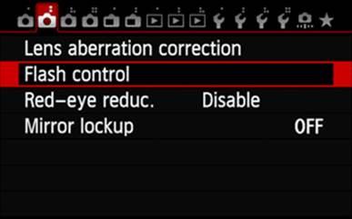
Figure 9-6. Selecting the Flash Control option
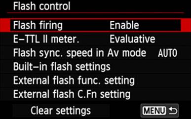
Figure 9-7. Choosing the Flash Firing setting
E-TTL II Meter.
The E-TTL II Metering option allows you to choose between Evaluative and Average. Both those metering choices function just as they do in the camera. Choose Evaluative for normal flash photography and Average for when it’s important that the entire image area be metered. Even then, it may be necessary to provide some degree of flash exposure compensation.
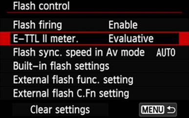
Figure 9-8. Selecting the E-TTL II Metering option
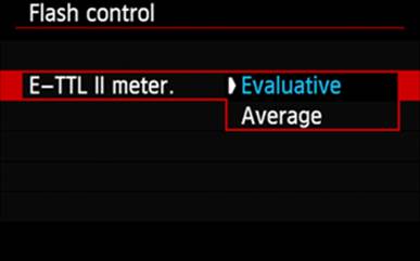
Figure 9-9. Choosing the E-TTL II Metering setting
Flash Sync. Speed In AV Mode
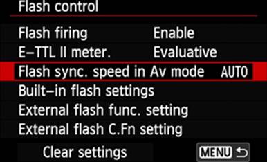
Figure 9-10. Selecting the Flash Sync Speed In Av Mode option
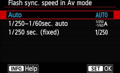
Figure 9-11. Choosing the Flash Sync Speed In Av Mode setting
The Flash Sync Speed in Av Mode option provides an opportunity to control what range of shutter speeds will be available when the Speedlite fires and the camera’s Mode Dial is set to Av. The Auto option will enable a range of shutter speeds from 1/180 second to as long as 30 seconds. If the exposure is going to require anything over 1/30 second (and sometimes not even that long), you will want to use a tripod or another means of ensuring there is no camera motion. The 1/180–1/60 Second Auto option reasonably ensures that the image will not be blurred because of a long exposure, but if capturing the background is important, you may find that 1/60 second is just not long enough. Simply providing more flash power will overexpose the subject and cast stronger shadows on the background. You need to either give the background more time (a longer shutter speed) for proper exposure, or provide some auxiliary lighting for the background. The third option, 1/180 Sec. Fixed, is good for limiting blurring caused by motion during the time the shutter is open, but any problems with well-exposed backgrounds will be even more apparent with this setting.
As shown in Figure 9-11, some menu panels will display the INFO button icon at the bottom of the screen. That serves to remind you that there is on-camera, menu-specific text that may be of value to you. To access that text, press the INFO button, then use the touch feature, the Quick Control Dial, or the Multi-controller to scroll down through the remaining pages in the help file. If you ask for a display of a help panel, and there is no red stripe down the right side of the text, then the help text is limited to that single page. To return to the Flash Sync Speed In Av Mode menu, touch the INFO icon or press the INFO button.
Built-in Flash Settings
These four settings apply only to the built-in flash, and are essentially ignored when an external flash is attached to the hot shoe.
Flash Mode
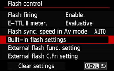
Figure 9-12. Selecting the Built-in Flash Settings option
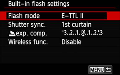
Figure 9-13. Choosing the Flash Mode setting
There are only two settings available for this option: E-TTL II and Manual Flash.
While E-TTL II is active, the camera will read reflected light and determine automatically when the light from the Speedlite should be extinguished. As is true for so many of the camera’s automatic functions, a majority of the results will be quite good, but there can be some tricky lighting situations, or even some creative artistic situations, when you will want to override the camera’s decisions. For such instances, select the Manual Flash option.
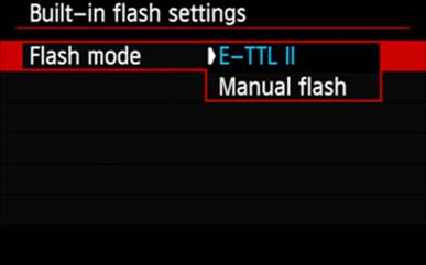
Figure 9-14. Selecting the E-TTL II option
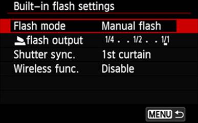
Figure 9-15. Having chosen the Manual Flash option
Internal Flash Output
In Manual Flash mode, the ability to select flash exposure compensation is replaced by the Internal Flash Output setting, which allows you to reduce the full flash output to suit your specific needs. The scale shows fractions of full output—each number is one stop less light output than the number to its right. You can see in Figure 9-17 that each stop is further divided into third-stop increments.
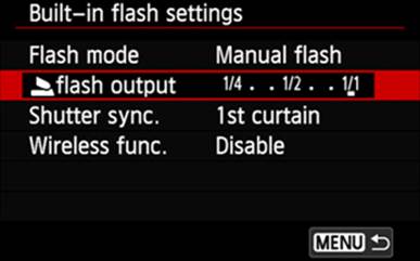
Figure 9-16. Selecting the Internal Flash Output option, for Manual Flash
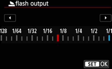
Figure 9-17. Choosing the Internal Flash Output setting, for Manual Flash
Shutter Sync.
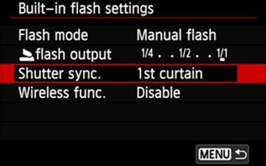
Figure 9-18. Selecting the Shutter Sync. option
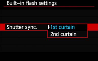
Figure 9-19. Choosing a Shutter Sync. setting
Shutter synchronization is a means of controlling when the flash is fired, relative to the start and end of an exposure. The term first curtain refers to the time at which the virtual first curtain of the shutter is dropped, starting the exposure. Conversely, the term second curtain refers to the time at which the virtual second curtain is dropped, ending the exposure. If flash is used, most situations will produce good exposures when the flash is fired immediately after the Shutter button is completely pressed (first curtain), but when you want to use a slow shutter speed to imply motion, using first curtain can result in a good exposure with the blurred portion of the image moving away from the sharp image, giving the wrong impression of movement direction. By using second curtain, you can capture the blurred image of the moving object, followed by a well-exposed image, giving a good and correct implication of motion in the correct direction. Be aware that if you are using the Second Curtain setting and the shutter speed is shorter that 1/25 second, the camera will automatically force first curtain shooting for that image.
Flash Exp. Comp.
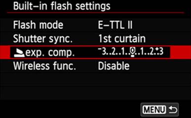
Figure 9-20. Selecting the Internal Flash Exp. Comp. option
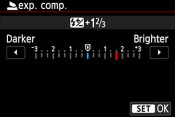
Figure 9-21. Choosing an Internal Flash Exp. Comp. setting
This option is replaced by the Internal Flash Output option when Flash Mode has been set to Manual Flash. This option is available in E-TTL II mode, and allows you to change the amount of light the camera has determined is appropriate. As shown in Figure 9-21, changes can be made in either direction—toward under-exposure or toward over-exposure—by as much as three stops, using one-third stop increments.
Wireless Func.
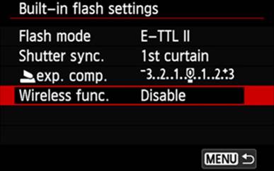
Figure 9-22. Selecting the Wireless Func option
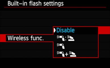
Figure 9-23. Choosing a Wireless Func setting
The built-in flash on the EOS 70D can function simultaneously as a flash and as a commander unit, wirelessly controlling one or several remote Speedlites. Such an arrangement—one that allows placing a flash to one side of (or even behind) the subject—helps eliminate the problems generally associated with having a source of light that is close to the axis of the lens. Complex, multi-flash configurations are also possible.
The commander function provided by the EOS 70D’s built-in flash depends on optical transmission of a coded set of low-intensity flashes to instruct the remote units. This introduces a potential problem: if you want to place a remote unit out of the direct line of sight of the commander flash, as there will be no communication between those two units. Choose your remote-unit placements carefully. (Using new radio transmission commanders and remote units eliminates this problem, but they are currently available only in the rather expensive 600EX-RT Speedlite. Since the radio transmission commander must sit in the hot shoe, the built-in flash is inoperative while using such a configuration.)
In Figure 9-23, pay particular attention to the flash icons on the right side of the screen. Using the top pair of icons as an example, note that the left-most icon of the pair represents an external remote Speedlite; the right-most icon is intended to look like the silhouette of the open, built-in Speedlite.
In the three icon images shown in Figure 9-23, the top image shows a pair of icons separated by a colon, which represents an external remote Speedlite set up to generate light as a multiple of the light generated by the built-in Speedlite. The available ratios range from 1:1, in which each unit is generating an equal amount of light, to 8:1, in which the external remote unit(s) will generate 8 times as much light as the built-in unit. This ratio of 8:1 is equivalent to three stops of external remote illumination for one stop of built-in flash illumination. As shown in Figure 9-25, this mode also allows setting flash exposure compensation, which applies equally to both the built-in and the external remote Speedlite units.
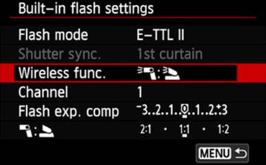
Figure 9-24. Selecting the Wireless Func. option
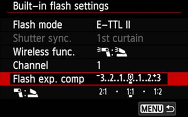
Figure 9-25. Selecting the Flash Exp. Comp. setting
The center image in Figure 9-23 is an icon for the external remote, only. Though the illumination will come from the external remote Speedlite, the built-in flash must be open and operational. When this mode is set, the built-in Speedlite will still send its coded flashes to the remote unit.
Figure 9-26 shows the Firing Group. With the All option selected, all remote Speedlites will be treated as one large flash. Alternatively, if your Speedlites have been organized into two groups (and a group ID of either “A” or “B” assigned to each), you can select the Firing Group: External Flash (A:B) option, and use the A:B Fire Ratio setting to establish the relative light output from the two groups, as shown in Figure 9-27. All units in a given group will perform the same, but one group can be set to provide a different amount of light than the other group.
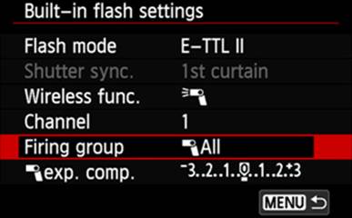
Figure 9-26. Selecting the Firing Group: All option
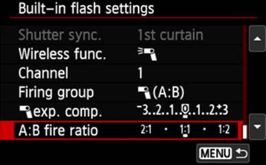
Figure 9-27. Choosing the A:B Fire Ratio option
At the bottom of this list is an icon pair separated by a plus sign, indicating that when in this mode, the built-in Speedlite and any external remote Speedlites will operate as two units. You have the ability to set exposure compensation for either or both units, allowing maximum flexibility in lighting control.
Going a step further, as shown in Figure 9-28, you can also support two groups of remote Speedlites as well as the built-in Speedlite. Take a close look at Figure 9-29: you now have the ability to set exposure compensation for the built-in Speedlite, separately set exposure compensation for the remote Speedlites, and set the firing ratio for the two groups of Speedlites.
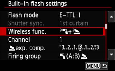
Figure 9-28. Selecting the E-TTL II Wireless Func option
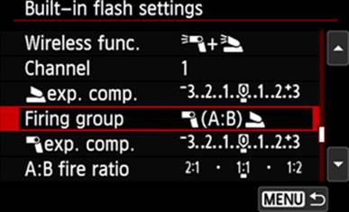
Figure 9-29. Choosing the wireless function Firing Group setting
Channel
When using the built-in Speedlite in wireless mode, the built-in flash and the remote units must all be set to use the same communication channel. Though different Speedlites may offer varying numbers of channels, the built-in flash can communicate over any one of four different channels. The most common reason for changing channels is interference from another photographer’s channel setup. By default, a professional photographer’s channel setup has priority over an amateur’s, but occasionally even the pros select conflicting channels; however, with a number of channels to choose from, a confrontation is rarely necessary to resolve this situation.
External Flash
A flash commander is capable of managing several remote flash units configured in numerous ways. The camera will expect to be able to communicate directly with a Speedlite, or a flash commander, mounted in the camera’s hot shoe, but that Speedlite or flash commander must be powered on in order to have a two-way communication with the camera.
In the course of discussing this menu item, I’ll be using the new Canon 600EX-RT Speedlite. As the Speedlite model numbers decrease, so does the number of features available. If I cover a feature in this section that does not appear on your flash unit, don’t get frustrated trying to find it. However, you may want to evaluate the feature and determine if you really can live without it.
Canon refers to their electronic flash units as Speedlites, so I will be using that term as well. Many photographers use electronic flash units and flash commanders from brands other than Canon, and they often must be managed differently than the Canon units. I won’t attempt to address all those possible combinations.
External Flash Func. Setting
The camera’s External Flash Func. Setting option allows many of a Speedlite’s configuration parameters to be set from the camera’s menu screens. In several instances, a given configuration parameter may be able to be set in either the camera’s menu or the Speedlite’s control panel; that usually means it can be set in both places, possibly to different values in each place. When a parameter is set in both places, the setting in the external Speedlite is always used and the camera is generally reset to match the setting on the external Speedlite’s control panel.
Canon cameras and Speedlites use a proprietary language to communicate with each other; therefore, if you mount any flash other than a Canon Speedlite, the camera can either ignore the flash or be thoroughly confused. You may see a message that says “incompatible flash.”
Flash Mode
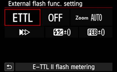
Figure 9-30. Selecting the Flash Mode option
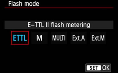
Figure 9-31. Choosing the E-TTL II Flash Metering setting
There are two options that are always available for Flash Mode: ETTL, which is the E-TTL II full-automatic through-the-lens metering system, and M, which is a fully manual flash system. More sophisticated systems may also offer a MULTI option that supports stroboscopic flash (multiple flashes per exposure), and possibly a Gr option designed to give you more extensive control over each group of remote Speedlites. In some instances, the Gr option will be replaced by the ExtA and ExtM options, which enable automatic or manual metering through the Speedlite itself rather than through the camera’s lens and sensor systems.
Wireless
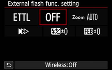
Figure 9-32. Selecting the Wireless option
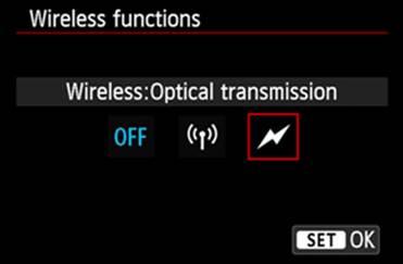
Figure 9-33. Choosing the Optical Transmission setting
With a wireless setting other than OFF, the camera treats the attached Speedlite as both a flash and a commander, unless it detects a commander-only device, such as the ST-E2 or the ST-E3-RT. An interesting exception is the 90EX Speedlite, which will function as a flash until this menu option is set to Optical Wireless, at which time it becomes a non-flash optical commander—it does not have the ability to function as both a flash and a commander at the same time.
Most of the Speedlites that can function as a commander are capable of transmitting control information only by using coded bursts of light, a technique Canon refers to as optical transmission. When you select the Wireless option, these Speedlites will show an OFF setting and a lightning-bolt icon setting. However, if you attach a 600EX-RT Speedlite, which is capable of commanding either optical transmission-controlled remotes or radio transmission remotes, the options are OFF, the lightning-bolt icon, and a radio antenna icon.
Depending on the wireless option selected, two more lines of icons will be added to the Flash Function Settings menu, allowing even more specific configuration. See the Speedlite’s manual for assistance on determining the best values to set.
Zoom
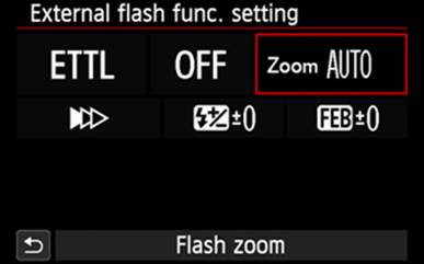
Figure 9-34. Selecting the Zoom option
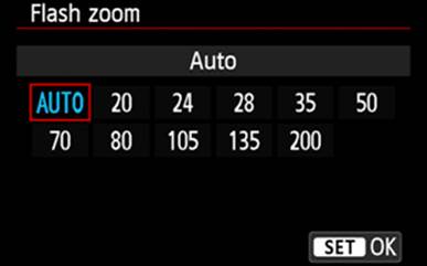
Figure 9-35. Choosing a Zoom setting
Some Speedlites provide an AUTO setting for this option. Such Speedlites communicate with the camera for an extensive amount of information, including the focal length setting for the camera’s lens, and will zoom the internal focusing system in the Speedlite to conform to the lens’s current focal length. Otherwise, you can select a focal length (just a bit shorter than the current lens’s focal length) to optimize the amount of light available. If you are manually setting this option and choose a focal length longer than the actual lens setting, you can expect to see dark, unlit edges.
Shutter Sync.
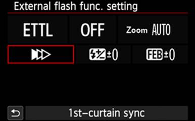
Figure 9-36. Selecting the Shutter Synchronization option
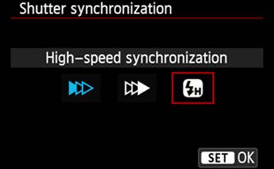
Figure 9-37. Choosing the High-Speed Synchronization setting
Shutter Synchronization refers to the correlation between the shutter movement and the timing of the flash from the Speedlite. Though often expressed in relatively small increments of time, shutter speed is still finite. With First-Curtain Synchronization, the Speedlite will wait until the shutter is completely open, and then fire the flash. This is the mode of operation we use most frequently. Occasionally, you may want to capture a picture showing the motion of your subject. This usually involves using a sufficiently long exposure to capture the subject in motion and firing the Speedlite just before the second curtain of the shutter closes to stop the motion so the subject is clearly identifiable. Because this technique is intended to show motion, it requires a shutter speed of 1/25 second or slower; any speed faster than 1/25 second will cause the camera to revert to First-Curtain Synchronization. Second-Curtain Synchronization is not available when you are using any form of wireless control.
As shown in Figure 9-37, the third icon represents High-Speed Synchronization. Using First- or Second-Curtain Synchronization forces the shutter speed to 1/250 second or slower, but you want to be able to capture an image using a faster shutter speed to stop as much motion as possible. The EOS 70D provides the High-Speed Synchronization setting for just that situation. Normally when we trigger the Speedlite, we expect it to fire the flash once, at maximum power. Varying the duration of the flash will determine how much illumination it provides. However, when the Speedlite is set to use High-Speed Synchronization, the Speedlite will determine the shutter speed set in the camera, then calculate the number of times it can flash in that time period, and set an initial percentage of full power to use for the first flash. Since there is insufficient time to recharge the Speedlite between each of the closely timed flashes, they are all fired at a level below maximum. With this approach, regardless of the shutter speed set, the Speedlite will provide illumination—albeit a bit less than maximum brightness—for the entire period the shutter is open, and the cumulative affect of those several flashes should yield a proper exposure.
Flash Exposure Compensation
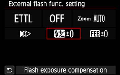
Figure 9-38. Selecting the External Flash Exposure Compensation option
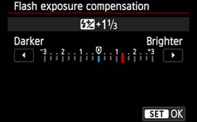
Figure 9-39. Establishing the direction and extent of flash exposure compensation
Flash Exposure Compensation gives you the ability to influence the amount of illumination the Speedlite will provide. After a test shot or two, you may determine that you need to provide more or less light. Rather than playing around with changes to ISO, shutter speed, or aperture, simply set the Flash Exposure Compensation to a value that will force the Speedlite to alter the amount of light released. Many Speedlites allow this adjustment to be set on the Speedlite, and several cameras allow you to set Flash Exposure Compensation on the camera itself (if set in both places, the setting on the Speedlite will override any setting on the camera). The EOS 70D will allow you to use the Flash Exposure Compensation option on the Quick Control screen to set the desired flash exposure compensation value. It also provides that capability through the External Flash Function Setting option in this menu. I’m not sure about other camera-and-Speedlite combinations, but in the case of the EOS 70D and the Speedlite 600EX-RT, when this menu is used to alter Flash Exposure Compensation, the Speedlite’s control panel is immediately updated, allowing you to readily confirm your action. If you use the Flash Exposure Compensation option on the Quick Control screen to modify the Flash Exposure Compensation, the Speedlite’s control panel is not updated until you press the Shutter button halfway.
The range of adjustment for Flash Exposure Compensation is +/−3 stops, in either 1/2-stop or 1/3-stop increments, depending on what you have selected for Exposure Level Increments in the C.Fn I-1 menu. Note that the increment selected in C.Fn I-1 will also be applied to the Speedlite 600EX-RT’s control panel.
Flash Exposure Bracketing
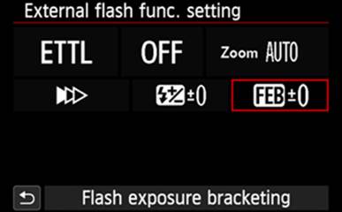
Figure 9-40. Selecting the External Flash Exposure Bracketing option
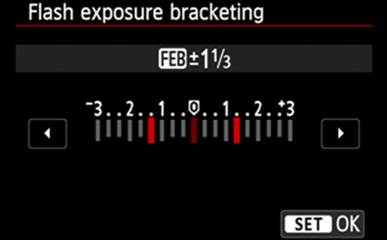
Figure 9-41. Setting the External Flash Exposure Bracketing range
Flash Exposure Bracketing allows you a bit of insurance by capturing three images: one at the calculated exposure, one with the exposure amended by the minus setting, and one with the exposure amended by the plus setting. This works only with the drive mode set to Single Shooting, and that requires you to trigger the shutter three times. These amended settings apply only to the second and third of the three exposures until you set FEB Auto Cancel (set at External Flash C.Fn Setting 3) to Enabled (at which point the camera will automatically turn off flash exposure bracketing after the three exposures). When that Custom Function is set to Disabled, the camera will continue to take one photograph with normal exposure, the next underexposed by the selected amount, and the third overexposed by the selected amount. If the camera used a three-shot burst mode for this operation, you would get three pictures of the same subject. Since you must press the Shutter button once for each of these exposures, if you forget to reset this option, you may wind up with a good exposure of the Tower of London, an underexposed photo of a double-decker bus, and an overexposed picture of the Queen’s Guard. I believe it’s better to leave this Custom Function set to Enabled, unless you have a long series of images to capture that all require bracketing.
External Flash C.Fn Setting
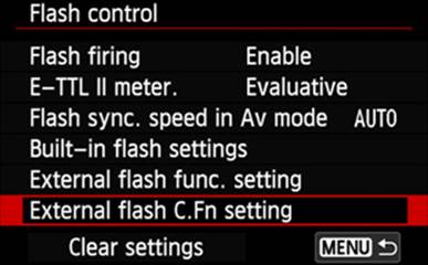
Figure 9-42. Selecting the External flash C.Fn setting option
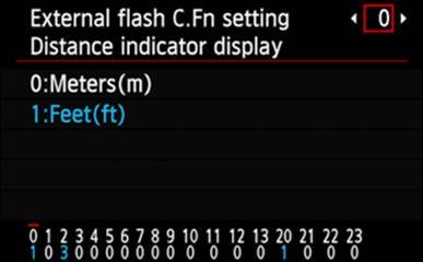
Figure 9-43. Selecting the first external flash custom function setting (number zero), Distance Indicator Display
The EOS 70D provides 18 different Custom Functions for an external flash. You may notice in Figure 9-43 that the numbers across the bottom of the panel reach 23, but not all numbers are used by this camera.
Navigating the maze of the flash-related functions that can be customized to your particular style is not intuitive. You will start with the panel shown in Figure 9-43. This is panel number zero, which represents Custom Function number zero. At the bottom of this panel you can see a short, red line over the upper digit (zero), which is simply another confirmation of which Custom Function is currently selected. Just below that zero is the number 1, which indicates the current offset, or displacement, into a list of values for this Custom Function.
If you wish to change the Distance Indicator Display from Meters (indicated with an offset of zero) to Feet (indicated with an offset of one), simply touch the Feet line twice; you can now use the Multi-controller to select another Custom Function for editing. If you prefer to use the dials and buttons, press the SET button. A bright red border will appear around the current selection, but you can use the touch feature, the Quick Control Dial, or the Multi-controller to make a new selection. To activate that new selection, press the SET button (you can also touch the MENU icon to set this selection, but the camera will take you all the way back to the Flash Control menu rather than simply allowing you to make more C.Fn selections). The selected value’s offset should now be on the bottom of the panel, directly under the number for the Custom Function. To scroll across the array of Custom Functions, use the touch feature, the Quick Control Dial, or the Multi-controller. To escape from this series of panels and return to the Flash Control menu, press the MENU button.
Some of the Custom Functions provide more than two settings, but the technique for selecting and confirming these settings is the same.
Clear Settings
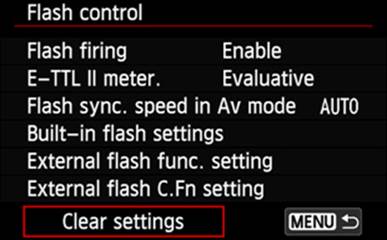
Figure 9-44. Selecting the Clear Settings option
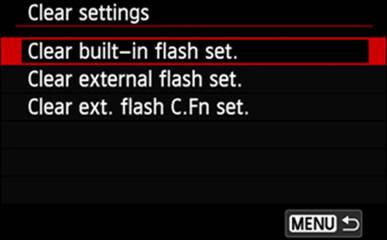
Figure 9-45. Choosing a Clear Settings setting
This option is too easily missed and misunderstood. Photographers sometimes assume it is not one of the External Speedlite Control options because it’s on the bottom line and indented. This option is a rare example of very poor, non-intuitive user-interface design on Canon’s part: selecting it and pressing the MENU button will not clear your settings. If you wish to clear either the built-in or external flash settings, or the external flash custom function settings, you should select this option and then select the appropriate option on the next screen. Pressing the MENU button while on the screen shown in Figure 9-44 will return you to the Shoot2 menu.
If you wish to clear only the flash settings and not the flash Custom Functions, select the Clear built-in flash set. option or the Clear external flash set. option (as shown in Figure 9-46) and press the SET button. Figure 9-47 shows that you can select either Cancel or OK. Once you have made that selection, press the SET button. Each of these three options will present a confirmation screen; if you select OK and press SET, all settings associated with that flash option are immediately cleared. Regardless of your selection, when you press SET, the camera automatically returns you to the Clear Settings menu.
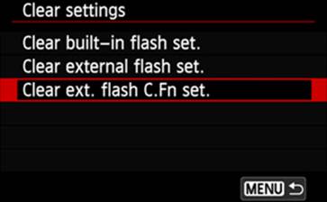
Figure 9-46. Selecting the Clear Ext. Flash C.Fn set. option
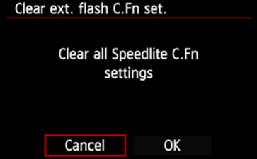
Figure 9-47. Choosing to cancel the Clear Ext. Flash C.Fn set. operation
The description of the Clear ext. flash C.Fn option in Figure 9-47 is not quite correct. When you use this option to reset the Custom Functions to their default values, all except the first are reset. You must manually use the External Flash C.Fn Setting option to access and reset Custom Function Zero.
From the Clear Settings menu, touch the MENU icon or press the MENU button to return to the Flash Control menu.
Red-eye Reduction
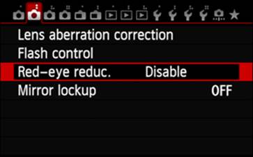
Figure 9-48. Selecting the Red-eye Reduc. option
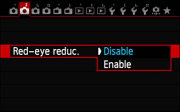
Figure 9-49. Choosing a Red-eye Reduc. setting
This function is not some hocus-pocus software implementation; it’s an operational feature that illuminates a reasonably bright light that will cause the subject’s pupils to constrict, reducing the amount of light admitted into the eye, thereby reducing the amount that is reflected back to the camera after gathering red coloration along the way.
For optimal effect, the light needs to stay on for very few seconds. While Red-eye Reduction is enabled, Canon replaces the exposure compensation scale at the bottom of the viewfinder with a similar (but non-graduated) scale that will start to diminish after the Shutter button is pressed halfway. You should hold the Shutter button in this halfway state until this scale disappears, then press the shutter button completely. There is no display of this scale, nor is there a specific illumination of the Red-eye Reduction lamp, if the DRIVE mode has been set to either of the self-timer positions. However, the self-timer and Red-eye Reduction share the same lamp, so as the self-timer winds down, the self-timer lamp accomplishes most of the red-eye reduction you would otherwise achieve.
Mirror Lockup
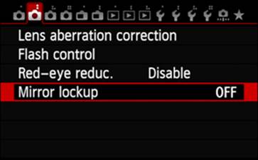
Figure 9-50. Selecting the Mirror Lockup option
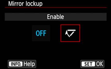
Figure 9-51. Choosing the Mirror Lockup Enable setting
Enabling Mirror Lockup consists of touching the option on the Shoot2 menu, touching the Enable icon, then touching the Set icon. Alternatively, you can select the option on the Shoot2 menu, press the SET button, use the Quick Control Dial or the Multi-controller to select the Enable icon, and then press SET again to return to the Shoot2 menu.
The text in the Mirror Lockup help panel is not quite complete. Yes, camera shake can be caused by mirror shock; but pressing the Shutter button to initiate Mirror Lockup introduces mirror shock. In order for Mirror Lockup to be of any value, you need to wait at least two seconds after locking the mirror in its up position before pressing the Shutter button again to actually capture the photograph. Notice that it takes two depressions of the Shutter button to capture the image.
Pressing the Shutter button the second time can introduce its own vibrations, which can easily exceed those of mirror shock. Therefore, I encourage you to consider using a good sturdy tripod, and either the camera’s self-timer or a remote control to trip the shutter. With the drive mode set to a self-timer option, the camera lifts the mirror when you first press the Shutter button, and then captures the image when the self-timer goes to zero; no second press of the Shutter button is required. A similar technique also works well with remote control, so if you do not want to use the self-timer, you can press the remote control’s shutter release to lift the mirror, wait two seconds, and then press the remote control’s shutter release again.
At the bottom of the panel shown in Figure 9-51, you can see a prompt to press the INFO button to access a help screen. This prompt warns you against pointing the camera at the sun while the mirror is up because it can seriously damage the shutter. Note that when in the help screen, you must press the INFO button again to return to the Mirror Lockup screen.
All materials on the site are licensed Creative Commons Attribution-Sharealike 3.0 Unported CC BY-SA 3.0 & GNU Free Documentation License (GFDL)
If you are the copyright holder of any material contained on our site and intend to remove it, please contact our site administrator for approval.
© 2016-2026 All site design rights belong to S.Y.A.