Creative flash photography : great lighting with small flashes: 40 flash workshops (2014)
Part I. What Every Strobist Needs to Know
You have a lot to learn before you can use flash in your sleep, and getting started can be tricky. This chapter provides a crash course in flash basics and introduces the gear you need to effectively use flash. You will learn how to fine-tune your skills using the sample setups in the individual workshop chapters that follow. If you find this chapter difficult, whet your appetite by looking at some of the workshops, then refer back to this chapter to find the answers to questions you may have. Of course, you can spend a lot of money on flash gear, but you don’t have to spend a lot to get started. I’ll show you what I keep in my camera and tripod bags and I’ll explain which equipment has been invaluable during my career.
Chapter 1. Flash Basics
▸ Up close and personal with spectra, the inverse square law, and guide numbers
▸ How to meter exposures and use light shapers
▸ Set up and unleash your flash
Even without flash, you need plenty of practice to successfully juggle exposure times, ISO values, and apertures while you shoot. Flash adds even more variables to the mix. The routine of everyday photography becomes more complex with the introduction of flash output, subject distance, angles of emission, and light-shaping tools. When you use flash, rusty old friends like exposure times need to be reviewed and you will need to learn new techniques like high-speed sync and second-curtain sync. The following sections explain the relationships among all these factors, andappendix A on page 266 includes some sample calculations for you to try.
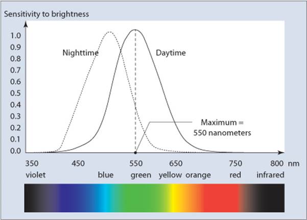
The sensitivity curve for the human eye and the corresponding visible spectrum
Let There Be Light!
Along with the main subject in an image, light is the most important aspect of the photographic process. If the light is right, you can make great photos, even using a simple cell phone camera. In extreme situations you may have to deal with too little or too much light, and this means that the sensor of your camera only delivers the tonal values black or white. Light can communicate information and evoke emotions. After you learn to work with light, you will be able to accentuate important parts of a scene and let less important elements disappear into the background.
Physically speaking, light is the part of the electromagnetic spectrum that can be visually perceived. The sensitivity curve for the human eye shows that we are capable of seeing wavelengths between 400 and 800 nanometers (nm) and that we are most sensitive to green tones. Dogs and camera sensors see light differently. Dogs, for instance, are red/green color blind, and digital image sensors can pick up near-infrared waves that the human eye cannot see.
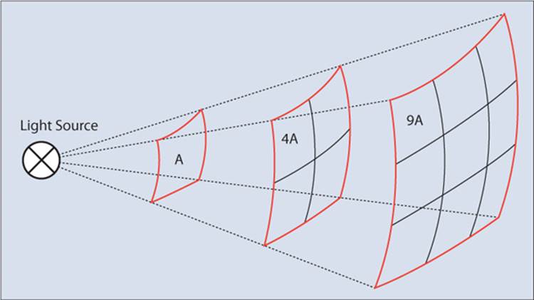
Light propagates in space according to the inverse square law, which states that the intensity of light close to its source is proportional to the inverse square of the distance to the source.
The inverse square law: If you double the distance between the subject and the light source, you will need four times as much light to illuminate a surface with the same intensity. If you triple the distance, you need nine times as much light.

The inverse square law: If you double the distance between the subject and the light source, you will need four times as much light to illuminate a surface with the same intensity. If you triple the distance, you need nine times as much light.
The inverse square law assumes that you are using a light source that radiates symmetrically. In the figure above you can see that only one-fourth of the light from the source is available to illuminate each of the four squares of the subject at double the distance. That is, the amount of light that reaches the subject decreases proportionally to the square of its distance from the light source. The inverse square law is especially important in flash photography, and we will revisit this concept many times throughout this book. Appendix A explains how to calculate with the inverse square law in real-world situations.
Continuous Light
Why is there a section about continuous light in a book about flash? The main reason is that the advantages and disadvantages of flash become even more obvious when flash light is compared with other light sources. The sun is the most widely used source of continuous light. It provides cheap, bright light with a useful spectrum and it’s available everywhere. But to tame sunlight you need to use reflectors, diffusers, shades, and other light-shaping tools. These tools transform hard, direct sunlight into a soft, diffuse source of photographic illumination. Unfortunately, the opposite is impossible; you can’t produce hard sunlight on a cloudy day.
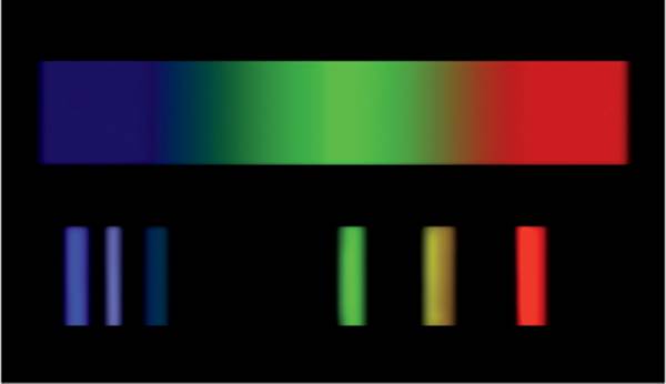
Some continuous light sources have problematic gaps in their spectrums. This figure shows the spectrum produced by sunlight or flash (top) compared to a typical energy-saving lamp (bottom).
The color temperature of ambient light varies during the day from warm gold to pure white to cool blue tones. If you need consistent light indoors or outdoors during the evening, you need to use either a continuous artificial light source or a flash. The major advantages of continuous light over flash are that it allows you to immediately see how your image will look, and you can use it to capture moving images. But the disadvantages outweigh the advantages. The light yield is relatively low, and many conventional sources of continuous light—halogen, neon, and light-emitting diode (LED) lamps, for example—produce illumination that is either too warm or too cool, or it simply has too many gaps in its spectrum. All continuous light sources require long exposure times, high ISO values, or both, which inevitably leads to increased image noise. Images taken with a flash usually look cleaner.
The Nature of Flash
Photographers have used flash since the very beginning of the photographic age. The first flash experiments used magnesium powder that was ignited by hand during the exposure. Nowadays, we use sealed glass tubes filled with xenon. One of the major reasons flash has become so popular is that it provides an extremely bright source of light for a very short period of time (see a comparison of continuous light and flash light on page 266 in appendix A). Xenon produces a visible spectrum with a color temperature that is similar to the midday sun, which makes it well suited to photographic applications. In contrast to neon or LED light, xenon has very few gaps in its spectrum. Flash light and sunlight produce great results when they are combined, and battery-powered flash units are small and easy to carry. They can allow the photographer to freeze action in an image, and their point-shaped light source is perfect for use with accessories such as umbrellas and softboxes. The following sections list the terms and units that are used to describe the light produced by a flash unit.
Flash Output | The energy released when a flash unit is fired is measured in joules (J) or watt-seconds (Ws). If you know the size of the capacitor in your flash unit and its charge voltage, you can calculate the energy stored in the capacitor using the following formula:
![]()
The output of most studio flash units is expressed in Ws (400 Ws is a typical value), but an accessory flash unit is often described in terms of its guide number (see the “Guide Numbers” section on page 8). Converting joules directly to guide numbers doesn’t work because guide numbers depend on additional factors, such as the light beam’s angle of reflection and the zoom setting of the flash reflector. If you need to compare accessory and studio flash units, you can generally assume that the most common models (SB-900, 580EX II, YN-560, etc.) have output values of around 60–70 Ws. The relationship between flash output and exposure value (EV) numbers is linear (see appendix A on page 266). If you double the flash output, the EV for the shot is also doubled.
Flash Duration | People often assume that flash durations are so short they are negligible when it comes to calculating exposures. However, when you use high-speed flash or another technically advanced technique, such as Supersync (also sometimes called pseudo-HSS or tail-sync hack), the duration is highly relevant. As the curve in the figure shows, flash duration is logarithmic rather than linear, and it is stated in terms of the two constants t0.5 and t0.1 which represent the time it takes for the flash output to subside to 0.5x and 0.1x of the full output. The following formula delivers a good approximation of the relationship between the two:
![]()
When you use an accessory flash, assume that the flash duration is approximately proportional to the output setting you use. For example, a Nikon SB-900 unit produces flash light for 1/20,000 second at t0.1 (minimum output) and 1/500 second at full output. If you want to freeze the movement of liquids or splashes, you need to select a low output setting and use additional flash units in parallel if one unit doesn’t provide enough light. Studio flash units often cannot be set to such low output power and therefore are generally slower.
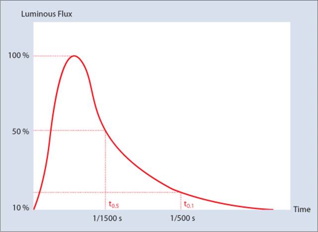
The flash durations t0.5 and t0.1 in relation to the curve of flash output over time
The relationship of flash output ~flash duration doesn’t always apply. Studio flash units often use multiple capacitors, depending on the current output setting. The best way to find the right setting for the shortest possible flash duration is to refer to the user’s manual or ask the manufacturer.
Guide numbers | A guide number (GN) is used to indicate how much light a flash unit can produce. The GN is defined as the product of the maximum distance at which the flash can illuminate a subject (A) and the aperture (B):
GN = A x B
Guide numbers can be quoted for specific angles of view and ISO settings. For example, for the Canon Speedlite 580EX II, the GN is given as 58 meters at ISO 100 and a zoom setting of 105mm. Because large numbers are more impressive, flash manufacturers usually quote guide numbers at the maximum (i.e., narrowest) available zoom setting. You can use the maximum subject distance or a known aperture setting to calculate the required guide number setting. If the ISO value changes, you can calculate the maximum flash range using the following formula:
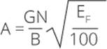
Here, the maximum distance or range, A, and the guide number, GN, are given in meters; B is the aperture setting; and EF represents the current ISO setting, which is usually assumed to be 100.
Examples of how to calculate using guide numbers are provided in appendix A on page 266.
Shaping and Directing Light
In addition to its spectral distribution and energy, light is also described in terms of its directionality and diffuseness, such as harsh direct sunlight, the soft light found in shade, or the light that enters through a north-facing window. Sunlight is a direct, point-shaped light source and creates well-defined, hard-edged shadows, whereas the light from a north-facing window is diffuse and forms soft-edged shadows. If neither sunlight nor light from the north is available, you can still produce various degrees of diffused light using flash and light shapers.
Diffusers function like clouds; they enlarge the light source and soften its overall effect. Reflectors—such as a white wall or a piece of Styrofoam—have a similar effect and also enlarge the light source. Because light that enters a north-facing window does not come directly from the sun and is scattered by the surroundings, this type of light is diffuse, even on cloudless days. The distance between the subject and the light source also plays a role; the closer the subject is to the light source, the larger and softer it will appear. The sun is an extremely large light source, but it’s very far away, so sunlight acts like a hard point of light.
Direct and Diffuse Reflection | If you point a small light source at a mirror, the reflected light will look nearly the same as the source light because the light is directly reflected. A mirror is therefore no use as a reflector unless you simply want to redirect the light. If you want to soften the reflected light, you need to use a textured matte surface to diffuse the reflection.
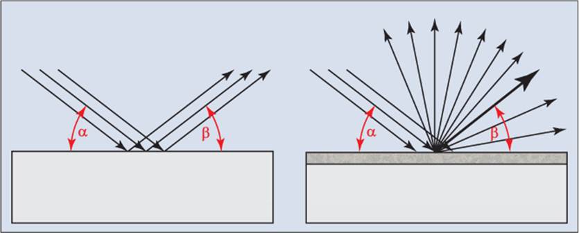
Just like in a game of pool, the angle of incidence of light rays is the same as the angle of reflection. The left side of the illustration shows the behavior of light rays hitting a smooth surface, such as a mirror. On the right, it shows how a textured matte surface partly diffuses the incoming light rays. This results in a mix of direct and diffuse reflection.
Playing off the Cushions | Just like the balls in a game of pool, reflected light and diffused-reflected rays follow the equation angle of incidence = angle of reflection. If you bounce light off a reflector, you have to keep this rule in mind when you position your lights.
Standard Light-Shaping Tools | In addition to reflectors, you can also use partially transparent diffusers to shape the light from a flash unit. Frosted and sandblasted glass make great diffusers, as do translucent foils, light-colored textiles, and paper. Diffused light allows you to produce more subtle lighting effects. The most widely used type of light shapers are 5-in-1 or 7-in-1 reflectors, which have a diffuser at their core and can be used with white, silver, or gold coverings. You can also use these reflectors with a black cover to reduce the amount of light that reaches the subject.
A translucent umbrella is a type of collapsible diffuser, and a reflective umbrella can serve as a simple foldable reflector.
Umbrellas produce soft light too, but because they are open at the back they can allow unwanted stray light to reach the subject. The idea of a closed umbrella led to the invention of the softbox—a kind of box-shaped diffuser with a rear covering that does not allow light to enter the box. The inside surface of the rear covering is lined with reflective silver material, which helps to increase the light yield. Softboxes can be square, octagonal, rectangular, or long and thin like a strip light. In contrast to diffusers and reflectors, which soften light, other types of light shapers can concentrate and shape light. Typical light shapers include snoots and honeycomb grids, which form and reduce light into narrow beams; barn doors allow you to precisely adjust the vertical or horizontal dispersion of light. You can also mount dark-colored flags close to the light source to darken specific areas of the scene.
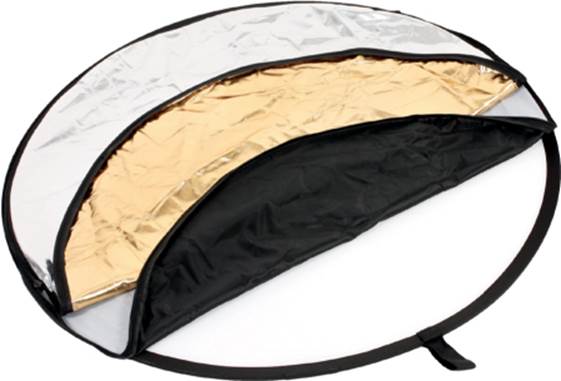
A 5-in-1 reflector set. The base can also be used as a diffuser. (Photo courtesy of EnjoyYourCamera)
The illustrations on pages 12–14 show various professional studio lighting products and the effects they produce. All these tools are available in versions designed to be used with a camera’s hot shoe, also referred to as system flash. It is important to remember that system flash units produce much less output than their studio equivalents, so they are not suitable for use with oversized reflectors or softboxes. Additionally, because these products have built-in reflectors, the light they produce is more direct. They can be effectively used with umbrellas, but they are less suitable for use with specialized accessories such as parabolic tele reflectors, which are designed to be used with omnidirectional light sources (e.g., sunlight that comes from all directions). There are two ways to work around this restriction:
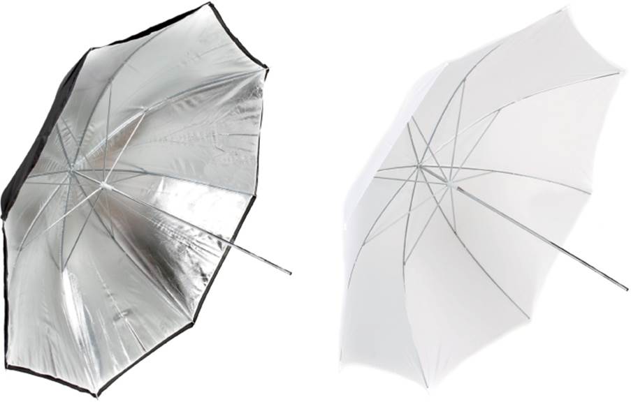
With a reflective umbrella (left), the flash is directed into the reflector and the light is reflected toward the subject. Conversely, the light from the flash shines through a diffuser umbrella (right). Both types of umbrella enlarge the light source and produce softer light. (Photos courtesy of EnjoyYourCamera)
▸Attach a clip-on diffuser to your flash. This produces a more omnidirectional light but reduces the flash output.
▸Modify your flash unit to work in bare-bulb mode. For details about how to do this, search the Internet for “bare-bulb flash.”
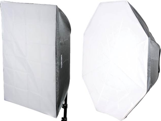
The insides of softboxes (left) and octaboxes (right) are coated with a silver material to increase the light yield. The effect they produce is similar to that of a diffuser umbrella, but without the risk of stray light escaping from the device. (Photos courtesy of EnjoyYourCamera)
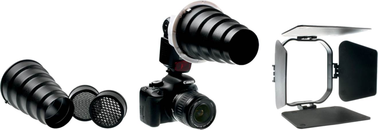
A snoot with honeycomb grids (left), a snoot mounted on an on-camera flash unit (center), and barn doors (right). These light shapers are used to reduce and direct the light to small spots or stripes. (Photos courtesy of EnjoyYourCamera)
Exposure Metering
Exposure metering for flash requires a different approach than metering in continuous light. The following sections provide detail about the available options and discuss which approach is best in certain situations. Also covered is how to mix flash and ambient light.
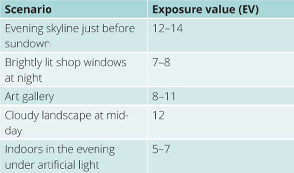
Using Tried-and-True Settings | The EV of a photo is an absolute value, so you can use standard values in situations with known conditions. The accompanying table lists a few sample situations and the values you can expect to use. Zero EV is assumed to be the result of shooting with an aperture of f/1 and an exposure time of 1 second (see also “Setting Exposure Using Known Values” on page 270). In real-world situations you will rarely use this method of adjusting your exposure, but it will help you develop a feel for what happens when you alter the exposure time or ISO value. For example, when you shoot indoors in artificial light, you need to use a relatively wide aperture, such as f/2.8, and an ISO value of 800 or more. In contrast, the sunny 16 rule states that in sunlight, if you set the aperture to f/16 and the exposure time to the inverse of the ISO value (e.g., 1/100 second at ISO 100, 1/200 second at ISO 200, etc.), you will probably produce a correctly exposed image. At ISO 100 and 1/200 second, you would need to set the aperture to f/11.
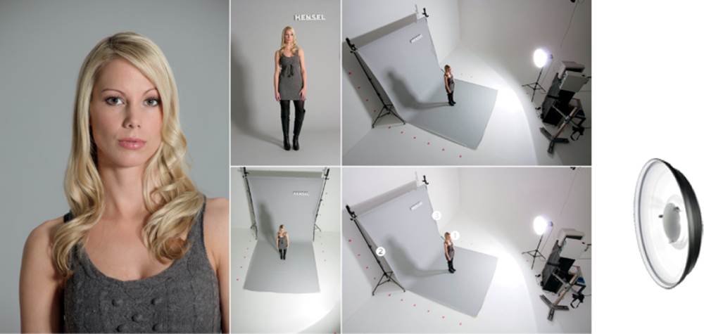
Type S 9˝ parabolic reflector, Expert Pro Plus 500, 88 Ws.
Metered apertures:
1f/8
2f/4 + 8/10
3f/4 + 6/10
Type S 9˝ parabolic reflector with #1 honeycomb grid, Expert Pro Plus 500, 189 Ws.
Metered apertures:
1 f/8
2 f/2.8 + 8/10
3 f/1 + 3/10
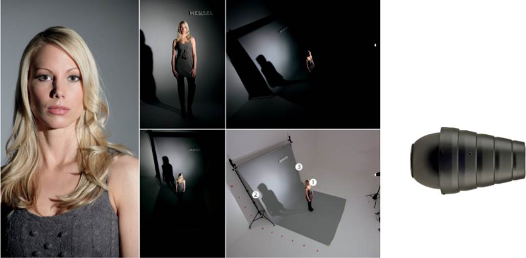
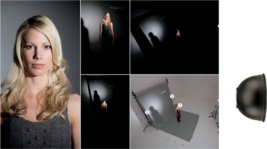
Hensel Accent Tube snoot and Expert Pro Plus 1000, 812 Ws.
Metered apertures:
1 f/8
2 f/4
3 f/1.4
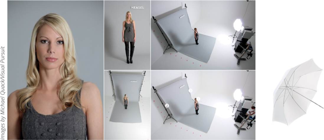
Hensel Softstar 42 in diffusion umbrella, Expert Pro Plus 500, 330 Ws.
Metered apertures:
1 f/8
2 f/5.6 + 2/10
3 f/5.6 + 8/10
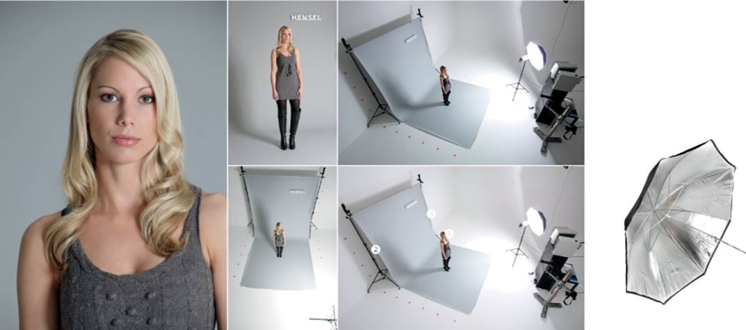
Hensel Master 42 in silver umbrella, Expert Pro Plus 500, 379 Ws.
Metered apertures:
1 f/8
2 f/5.6 + 2/10
3 f/5.6 + 5/10
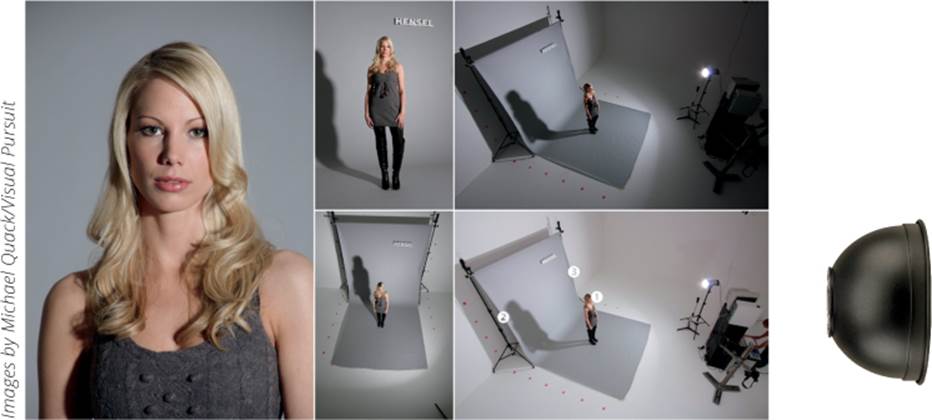
White Hensel beauty dish, Expert Pro Plus 1000, 616 Ws.
Metered apertures:
1 f/8
2 f/5.6
3 f/5.6 + 5/10
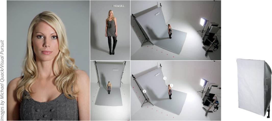
Hensel softbox 18 x 26 in, Hensel Tria 3000-AS with EH Pro Mini head, 462 Ws.
Metered apertures:
1 f/8
2 f/4 + 8/10
3 f/5.6 + 1/10
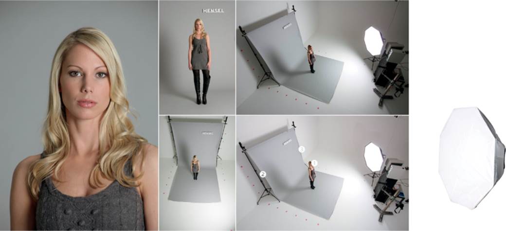
Hensel Octaform 60 in octabox, Hensel Tria 3000-AS with EH Pro Mini head, 350 Ws.
Metered apertures:
1 f/8
2 f/4 + 7/10
3 f/5.6 + 2/10
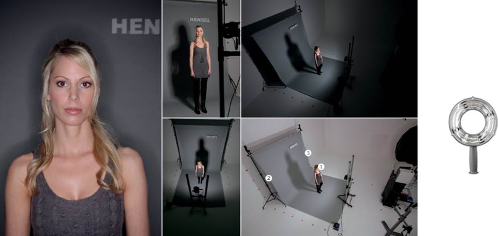
Hensel 3000-AS Ringflash with EH Pro Mini head, 462 Ws.
Metered apertures:
1 f/8
2 f/4 + 8/10
3 f/5.6 + 1/10
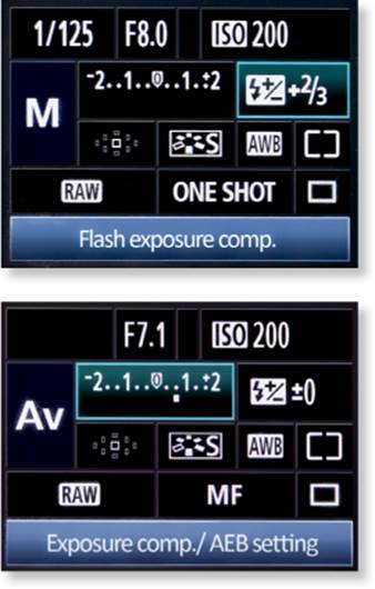
Flash exposure compensation (top). In auto exposure mode (bottom), exposure compensation can be used to influence your results.
The exposure meter display works in manual mode too
Because 1/200 second is the standard flash sync value for many cameras, it’s an important base value if you want to use additional flash (see “Flash Synchronization” on page 25). Although the formula works only for available light, you can still use it as a jumping-off point to calculate settings for flash shots that also include ambient light.
Using the Camera’s Built-in Light Meter | If you use your camera’s automatic exposure mode, you are sure to use the built-in light meter often. In this mode the camera uses readings from the built-in exposure meter to automatically set the exposure time, aperture, and ISO value. You can adjust the exposure by using the camera’s exposure compensation function.
If you then mount a through-the-lens (TTL) flash unit from the same manufacturer as your camera, the camera will automatically adjust the exposure. Again, you can influence the exposure by adjusting the exposure compensation. I find that automatic exposure metering produces slightly inconsistent results from shot to shot, so I use it only if I’m in a hurry. You will get more stable and predictable results if you shoot in manual (M) mode and take your time to carefully meter each shot. Keep an eye on the viewfinder meter display to help you judge the ambient light while you shoot. If you use the built-in meter as the basis for your calculations, it is important to remember that the readings assume the subject has a reflectivity of 18%. If you base your measurements on a reading from a standard gray card, everything will be fine. If, however, you take meter readings from pale skin or white textiles, you will have to deliberately overexpose your shot (e.g., between 2/3 and 1 1/3 stops) to prevent the image from turning out too dark. A useful way to set up your camera for a portrait shot using ambient light is to turn off autofocus and switch to center-weighted metering before you switch to manual (M) mode, then zoom in so the subject’s face fills the frame. Adjust the exposure so the meter reading in the viewfinder is at 0, and then add 2/3 stop of overexposure.
If you are able to operate your camera controls without looking, you can use this method to set a correct exposure without taking your eye away from the viewfinder. This procedure can also work in spot and matrix metering modes. I often use spot metering in tricky situations, and I use center-weighted metering for general shooting.
This approach to metering will also help you practice non-TTL flash metering. If you want to block out the ambient light in a scene, you can keep an eye on the appropriate level of underexposure in the viewfinder display, and if you want to include ambient light in your shot, you can also adjust the exposure on ambient light in this way.
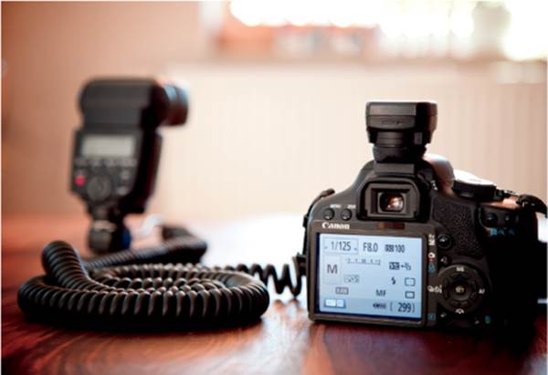
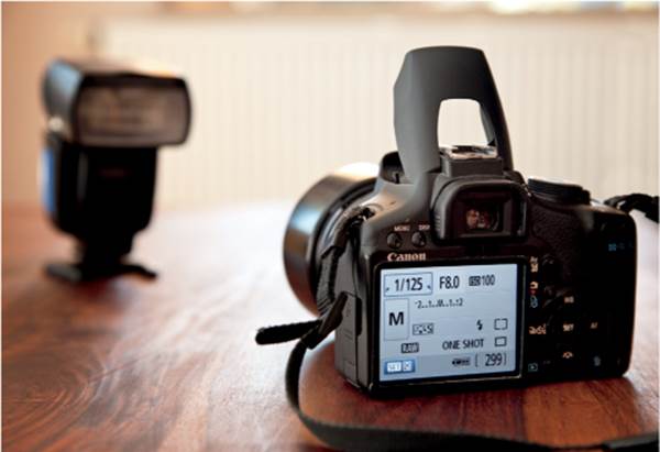
Using a Separate Light Meter | Apart from the special case of TTL flash metering, built-in exposure meters can measure only continuous light sources. To work around this limitation, you can use a separate handheld exposure meter that calculates the exposure value or aperture (if you preset the ISO value and exposure time).
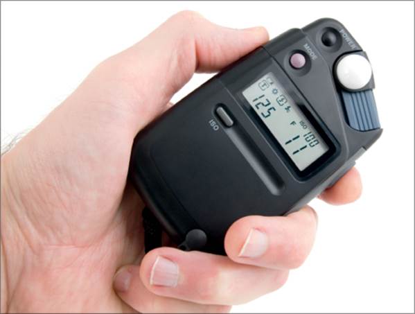
The photographer has preset ISO 100 and 1/125 second, and the meter has calculated an aperture value of f/11 (Photo courtesy of Arturko, Fotolia.de)
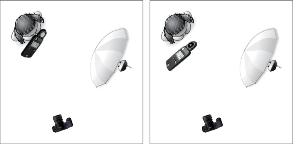
High-end light meters allow you to meter the light coming directly from the source or the light reflected by the subject
Most studio photographers meter the light that comes from their lamps, even though this increases the risk of dark objects turning out too dark and light objects turning out too bright. Metering reflected light allows you to better judge the correct exposure for complex subjects.
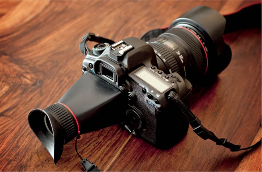
A screen loupe enlarges the monitor image and makes it much easier to judge the quality and sharpness of your images, regardless of how bright the ambient light is
Many of today’s light meters can also be used to meter flash light, either by using a built-in sensor to measure the peak flash intensity or by RF-triggering these devices parallel to the flash unit itself. To use a flash meter, begin by setting reasonable base values, such as ISO 100 and 1/125 second, before you turn on the meter and fire the flash. If the meter indicates an aperture of f/11 for a correct exposure, but your planned shot requires a larger aperture, simply dial in the appropriate value on your flash. Remember that each full f-stop doubles (or halves) the flash output. If your flash unit supports smaller increments between full f-stops, each increment usually represents 1/3 stop or 1/10 stop.
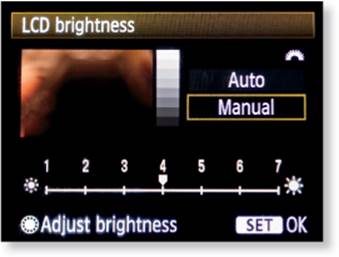
Metering Using the Camera Monitor and Histogram | This metering method involves taking a test shot and checking it visually (with the help of the overexposure warning) on the camera monitor. This is a fast and reliable way to judge your exposure. Camera monitors are small, but they display adequate image quality and show precisely how the light is distributed in the image. You can quickly judge if the main and accent lights are placed correctly and if you have struck a good balance of flash and ambient light. If the image in the camera monitor is too bright or too dark, you can turn off the auto brightness function. I always do this and set a static medium brightness value. In bright light, a dedicated screen loupe is a great tool to help you accurately see the preview image. I also use the highlight overexposure warning function (the blinking overexposed areas) to help me identify any clipped highlights.
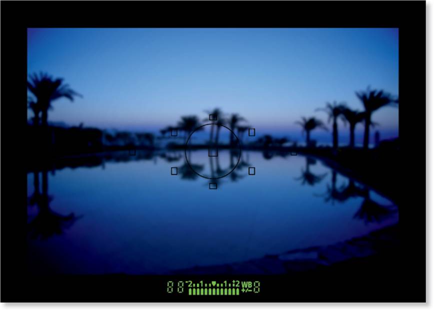
If you use your camera monitor to evaluate the exposure, always switch off the automatic brightness control, and if possible, use a screen loupe
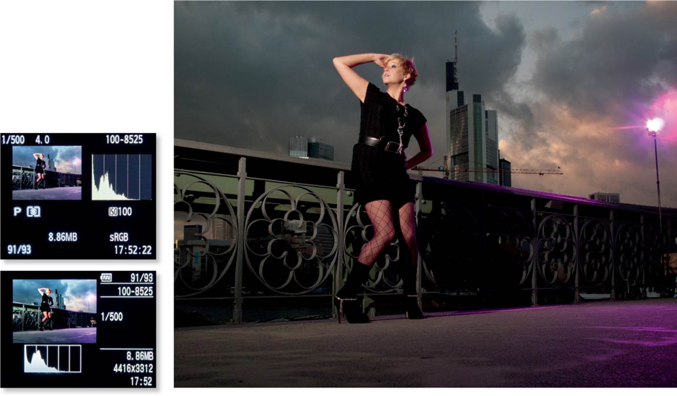
The histogram is also a useful exposure aid. A well-exposed photo will have a histogram curve that approaches, but doesn’t touch, the right side of the graph. With a little practice, you will learn to identify which parts of an image are represented in the histogram by the peaks and valleys. In the sample image in the accompanying figure, for example, you might decide that the sky is of less importance than other areas of the image. The blown-out highlights might not matter, and you may decide that retaining the shadow detail on the fronts of the buildings is worth the overexposure.
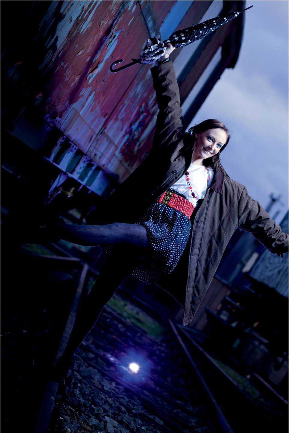
On the other hand, you can expose backlit subjects to retain background detail while the subject appears as a silhouette. The histogram for the image of a mannequin makes it easy to tell if the image is correctly exposed. For example, in the backlit shot of Kimi on the next page, the background plays a secondary role and the blinking warning areas do not matter.
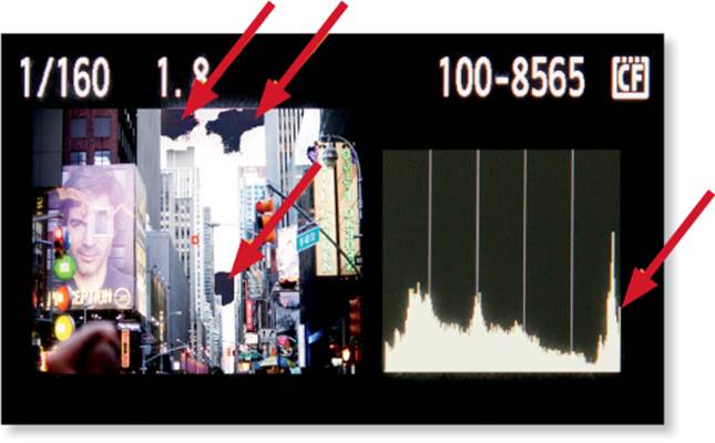
The arrows pointing to the blinking areas in the image (left) are reflected in the histogram (right). Note that the peak on the right side of the histogram shows the overexposure: these areas of the image are blown out (i.e., they contain no usable data).
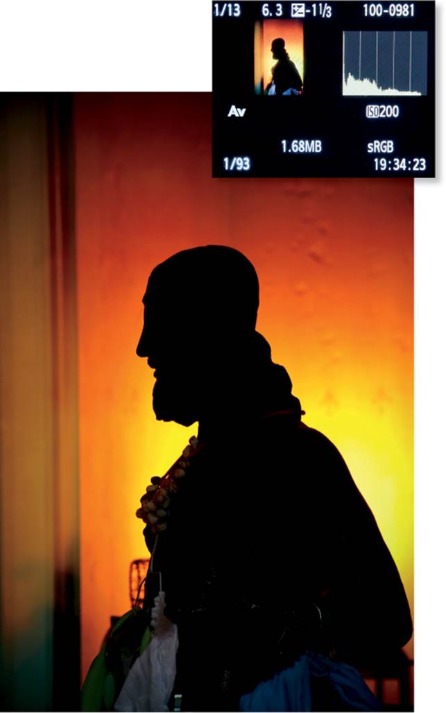
The histogram indicates a perfect silhouette with deep, saturated blacks and no blown-out areas in the background
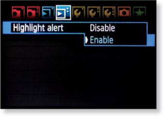
The histogram warning function is enabled so you can see if you need to adjust the exposure
There are only a few bright areas in the image (the model’s face and arm, and the light in the background), and that makes this image appear underexposed in the histogram, but it is correctly exposed. The screenshots are from a Canon EOS Rebel T1i (EOS 500D) (top) and a Canon PowerShot G10 (bottom). (Model: Layka)
I shot the above photo with a Canon PowerShot G10. This combination of camera and subject required a lot of care when it came to identifying the few relevant peaks at the right side of the histogram. Be careful when you shoot subjects that don’t fill much of the frame. Depending on the scene and the camera, it can be extremely difficult to correctly identify the parts of the histogram that relate to the subject, which makes it hard to evaluate the exposure. In this case, it was preferable to using the camera’s display or checking the blinking histogram warning.
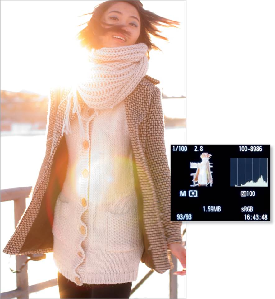
The blinking areas show that the strong backlight completely burns out the background, but the model is correctly exposed (Model: Kimi)
You need to know your camera monitor well if you want to use the histogram and the blinking warnings to evaluate your exposures. If you change camera systems (for example, from Canon to Nikon), you will need to get used to the behavior of the new camera. Different cameras indicate overexposure at different thresholds, and the monitor brightness varies from camera to camera. As previously mentioned, using consistent monitor brightness and a screen loupe will greatly help you to evaluate your exposure correctly. With a little practice you will be able to judge the exposure by eye almost as well as if you used a light meter. If you master this approach, you will be in the company of an illustrious group of pro photographers that includes David Ziser, Neil van Niekerk, David Hobby, Joel Grimes, and Kevin Kubota, all of whom rarely use light meters.
Manual Flash Settings
There are various ways to manually set up non-TTL flash units. The simplest approach is to suppress the effects of ambient light and illuminate the subject using flash only. Things get more complex when you want to mix natural light and flash.
Flash without Ambient Light | This is the easiest type of shot to set up. Begin by using settings such as ISO 100 (for low noise), f/5.6 (for sufficient depth of field), and 1/125 second to ensure that there are no conflicts with your camera’s sync speed capabilities (discussed later). Place your flash as close to the subject as possible but far enough away to ensure that the entire scene is sufficiently lit, and then set the flash output to 1/4. You can fine-tune the output setting after you take one or two test shots, but remember to make your first test shot without flash to check that you have suppressed the ambient light. Because the flash duration is much shorter than the time the shutter is open, only the aperture, subject distance, and flash output determine the look of the image—the length of exposure has no effect. The only exception is when you use high-speed sync (HSS) techniques (see page 25).
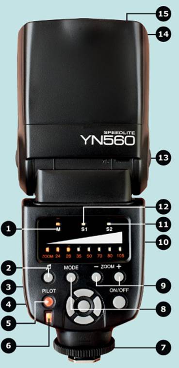
The generic YN-560 strobist flash has no built-in TTL functionality and must be controlled manually
1 Standard manual mode
2 Flash ready sound on/off switch
3 Battery pack connector
4 PC sync socket
5 Charge indicator lamp/test flash button
6 Power save indicator
7 Locking ring
8 Mode switch (M, S1, S2)
9 Zoom +/–
10 On the front: optical sensor for slave firing
11 Slave mode with preflash suppression
12 Slave mode
13 Articulated tilt/swivel joint
14 Reflector
15 Wide-angle diffusor
Other Options
If you don’t have enough flash power, you can always increase the ISO value. If the ambient light is too bright, adjust the exposure time to match your camera’s sync speed (usually 1/200 or 1/250 second). If these adjustments don’t solve the problem, see the “High-Speed Synchronization” section later in this chapter.
This strobist-style manual flash setup requires more effort, but you won’t need to use a flash with any kind of smart features or built-in electronic trickery. In fact, you can use the cheapest flash units you can find. The accompanying figure shows the Yongnuo YN-560 model, which is a widely used, low-cost flash unit. Each LED represents a full stop (i.e., each increment halves or doubles the flash output). The YN-560 provides just as much flash output as the Canon Speedlite 580EX II at about an eighth of the cost. Canon’s Speedlite, on the other hand, offers advanced features such as TTL auto mode, high-speed sync, wireless flash control, and stroboscopic mode—and, of course, you can also use it in manual mode as an expensive alternative to a strobist flash.
Combining Ambient Light and Flash | In the right situation, ambient light and flash light can be mixed to produce interesting results. Try capturing the mood at dusk by combining the artificial lights in a scene with a flash-lit subject. In such cases, the exposure time determines the proportions of flash light and natural light in the image. Longer exposure times allow more ambient light to reach the sensor. You don’t need to change the amount of flash light you use, but you do have to slightly underexpose the main subject. If the subject is correctly lit by the ambient light, adding flash will overexpose it.
Begin by selecting camera settings that expose the scene correctly without flash, and then underexpose the background by 1 or 2 stops to make sure it looks good. Check the meter readings and the results on the camera monitor before you add flash to light the subject.
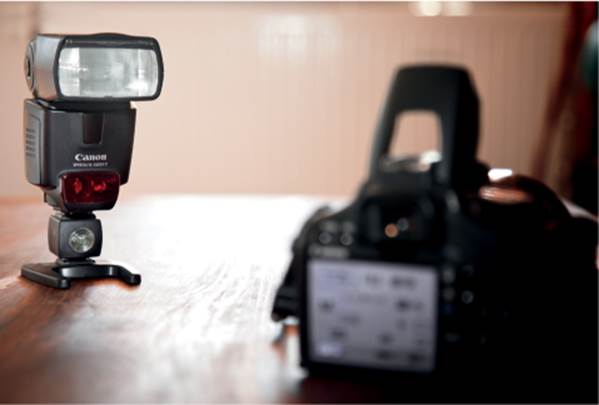
Manually Controlled Off-Camera Flash Units | Using manually controlled off-camera flash units provides a number of advantages. You can choose the flash-to-subject distance and the direction the flash is facing, and you can use light modifiers to fine-tune the flash effect. You can remotely fire off-camera flash in non-TTL mode by using a cable or an infrared release. Flash cables come in a variety of shapes and sizes, and all TTL cables can be used to fire flashes that are set to manual mode. The top-left figure on page 22 shows the Yongnuo OC-E3 cable. It has hot shoes at both ends so you can use it with flash units that don’t have a PC socket.
Most flashes can be fired remotely using the built-in optical sensor. If the direct light from the master flash unit on the camera spoils the lighting, you can cover the reflector with an infrared filter (for example, the Nikon SG-3IR IR Panel for built-in flash).
The most elegant and robust way to fire a flash unit remotely is with a radio control. This high-end technology has now reached the mass market, and modules from Asian manufacturers, such as the Yongnuo RF-602, are highly recommended. PocketWizard is another manufacturer of flash accessories that offers additional features, such as TTL functionality and a slightly better build quality than Yongnuo products.
Some cameras have built-in wireless flash control functionality and therefore require no additional accessories if you use flash units made by the same manufacturer. Cable, optical, and slave release systems generally work with any make of camera and flash. Exceptions to this rule are cameras made by Sony because they use a proprietary flash shoe. However, adapters are available.
Connecting an off-camera flash unit with a cable. This is the simplest, cheapest, and most reliable way to remotely fire a flash, though it comes with the risk of stepping on the cable. The Yongnuo OC-E3 cable shown here is suitable for manual or TTL use with Canon flashes. Similar cables are also available for flashes made by Nikon and other manufacturers.
An off-camera flash unit (here, the YN-560) fired using its built-in optical sensor. This is a cheap way to fire off-camera flashes, but it only works at short distances. An articulated shoe-mounted flash used as a master unit would offer more power and hence more control than the popup flash shown here.
An off-camera flash unit fired with an accessory optical slave unit from Kaiser. The figure shows a Canon flash (that has no built-in optical slave cell of its own) mounted atop the Kaiser unit. This is a cheap solution that works best over short distances, but only if the master and slave devices have clear visual contact.
The Yongnuo RF-602 is a non-TTL radio trigger (the transmitter is mounted on the hot shoe and the receiver sits under the off-camera flash). This simple, cheap solution works over relatively long distances. It requires no direct visual contact with the slave and even works through concrete walls. The drawbacks are that this model does not offer TTL (auto) flash and does not support high-speed and second-curtain sync.
TTL Technology
TTL technology is the successor to an earlier flash technology that used a built-in sensor to calculate the necessary flash output, independent of the camera’s own circuitry. As the name suggests, TTL (through-the-lens) technology meters flash directly through the camera’s lens and ensures that the light emitted by the flash unit corresponds perfectly to the scene and the angle of view of the lens. A TTL system fires a preflash that the camera circuitry uses to calculate the correct exposure and transmit the corresponding data to the flash. The flash unit then uses the data to calculate the correct flash output setting. This complex data transmission requires high-end technology in the camera and the flash unit, as well as a high-tech interface between the two. TTL-capable flash units are easily recognizable by their multiple hot shoe contacts. TTL software and hardware is generally proprietary to the manufacturer, although third-party manufacturers—such as Nissin and Metz—make flash units that are compatible with Nikon, Canon, Sony, Pentax, or Olympus systems, but still you have to choose the right type for your flash. The figure on the next page shows the popular Canon Speedlite 430EX II.
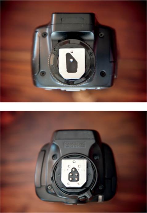
A non-TTL hot shoe (top) has two contacts: ground and fire. A TTL hot shoe, like the one from Canon (bottom), has multiple contacts that transmit complex control signals and exposure data between the camera and the flash unit.
Metering Modes | In TTL mode, the camera controls the exposure by using techniques that are very similar to the familiar spot, center-weighted, and matrix metering methods used in continuous light situations. Canon’s TTL technology offers center-weighted and matrix modes, and other manufacturers offer similar options. Canon and Nikon offer spot flash metering—called Flash Exposure Lock (FE Lock) by Canon, and Flash Value Lock (FV Lock) by Nikon. FE Lock and FV Lock save spot-metered exposure values that you can then use to light a reframed image; this technique is often called meter and recompose. Spot metering/FE Lock is used in the first workshop, allowing the preflash to be decoupled from the main flash. With this trick, it’s possible to even use slave flashes without preflash suppression.
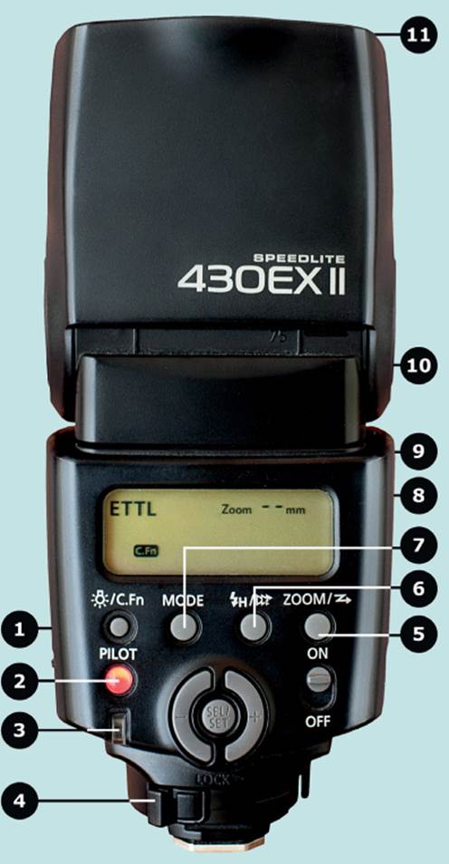
The Canon Speedlite 430EX II TTL flash
1 LCD panel illumination/custom function button
2 Pilot lamp/test firing button
3 Flash exposure confirmation lamp
4 Hot shoe Lock release button
5 Zoom/wireless setting button
6 High-speed sync/2nd curtain button
7 Mode setting button (TTL/manual mode)
8 On the front: wireless TTL sensor
9 On the front: AF-assist beam emitter
10 Tilt/swivel flash head and locking button
11 Wide-angle diffusor
Combining Flash and Ambient Light in TTL Mode | TTL technology makes it easy to mix flash and ambient light. Just meter the scene (without flash) using one of your camera’s auto modes, reduce the overall exposure value using exposure compensation (EC), turn on your flash unit, and shoot. The flash will automatically illuminate the main subject with the correct output. In a situation like this, for the flash, the Canon system ignores any EC settings you make and always meters the flash for the main subject, whereas the Nikon system automatically incorporates the compensation value in its flash calculations. To work around this, you have to use the flash exposure compensation (FEC) function on the flash unit to balance out the camera-based EC setting. For example, if you set an EC value of –1 EV, you have to set an FEC value of +1 EV to compensate. The Canon and Nikon systems function almost identically in manual mode. You can meter for the ambient light and let the flash automatically calculate the correct lighting for the main foreground subject. The only difference is that Nikon’s EC values also influence the exposure in manual mode. This may seem a bit strange, but at least it’s consistent with the behavior in aperture-priority (AV) and shutter-priority (TV) modes, and it enables the user to bias the exposure metering display in manual (M) mode.
If you are shooting in a tricky situation, such as in low natural light, it’s better to set the camera to manual mode and draw on your experience to select the best camera settings (the ISO-setting that is tolerable with the camera regarding noise, the shutter speed that can be used handheld, and the aperture that is tolerable regarding DOF) instead of relying on the camera’s automatic exposure meter. This way you will control the amount of ambient light that is included in your exposure, and the TTL flash will control the illumination of the main subject. By now, you have probably realized that TTL technology is a somewhat elusive science. If you want to get the most out of your TTL equipment, it is essential to thoroughly study your camera and flash manuals and take plenty of test shots under a wide range of conditions.
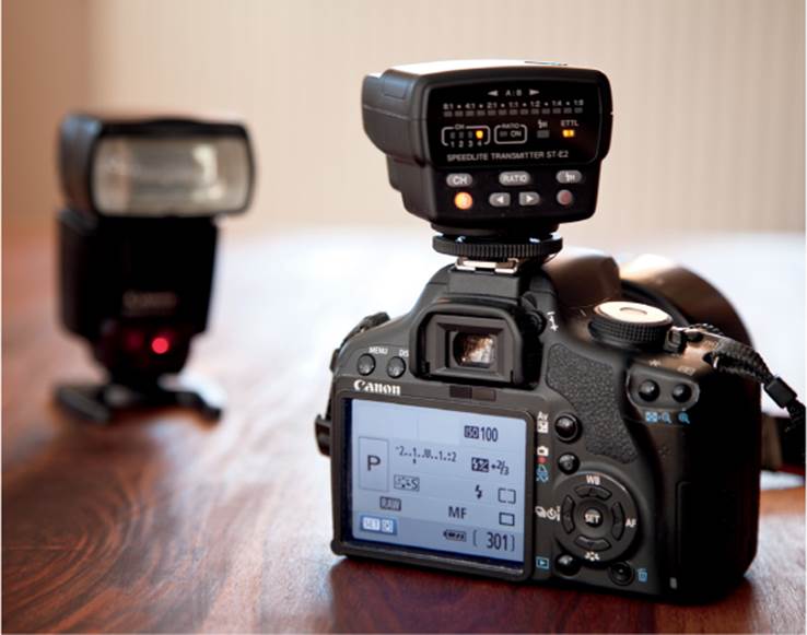
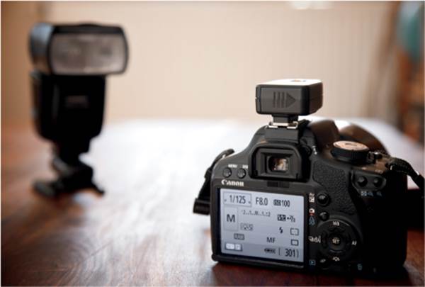
TTL off-camera flash control using a Yongnuo ST-E2 as the master and a Canon Speedlite 430EX II as a slave. This is a relatively inexpensive and reliable solution, but it requires a direct line of sight between the units. A Canon flash, such as the Speedlite 580EX II, could also be used as a master in this setup (a second 430EX II would not work, because it doesn’t have built-in master functionality).
Off-Camera TTL Flash | TTL flash can be used off-camera, most easily and cheaply with a manufacturerspecific flash cable, but there are better solutions. The major manufacturers have developed their own optical flash control systems based on either infrared technology (Canon) or pulsed flash (Nikon Creative Lighting System, or CLS). Some Canon cameras (such as the EOS 7D) have built-in master functionality, and others require a proprietary or third-party shoe-mounted infrared transmitter, such as the ST-E2 module (available from Canon and, in a clone version, from Yongnuo).
Radio control is a reliable (but more expensive) way to control flash, and it does not require a direct line of sight between the transmitter and the receiver. Canon offers the Speedlite 600EX-RT radio-controlled flash system, and the MiniTT1 from third-party manufacturer PocketWizard is compatible with Canon and Nikon flashes.
Flash Synchronization
A flash unit normally must fire while the shutter is open. The following sections describe how the simultaneous interaction of flash and focal plane shutter can be achieved.
Focal Plane Shutter | Most current digital singlelens reflex cameras (DSLRs) have a two-curtain focal plane shutter that works in standard mode, as shown in the figure below-left. When the shutter is released (t0), the first shutter curtain descends until the sensor is completely uncovered (t1). The sensor is exposed to light from the start of the process (t0) and is fully revealed between t1 and t2. The second shutter curtain then descends to cover the sensor, and the shutter movement is complete at t3. If the condition for successful flash synchronization isn’t upheld—that is, the exposure time is shorter than the camera’s flash sync speed (1/200 second for Canon and 1/250 second for Nikon)—the sensor is never completely uncovered, resulting in a stripe that appears at the bottom of the frame, as shown in the photograph on page 26.
To avoid having a black stripe across the frame, you can use high-speed synchronization (HSS). The alternative, SuperSync (also called pseudo-HSS or tail-sync hack), is not supported directly by the major camera manufacturers, but I explain how to use it in workshop 4.
In practice, if you use RF-triggered off-camera flash, you will need a little headroom in your exposure times to compensate for the slight lag due to the RF transmission. A shutter speed of 1/125 second is a good choice in most situations.
High-Speed Synchronization | In high-speed sync mode, the flash unit not only emits a preflash and then a main flash, as in standard mode, but it pulses like a strobe light for the entire duration of the exposure. The multiple flashes have the same effect as a continuous light source, which eliminates the problem of a black stripe in the image. In HSS mode, you have to calculate the exposure values as if you were shooting in continuous light. For example, if you halve the exposure time, you will have only half as much light to play with (see the sample exposure calculations onpage 266). Note that with most flash units you can set this HSS mode even while in manual mode, thereby eliminating the metering preflash.
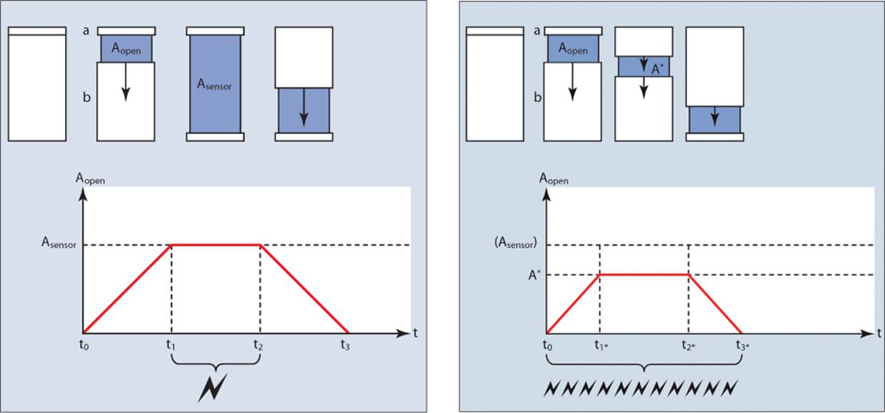
The figure on the left depicts successful synchronization. The figure on the right shows an exposure time that is too short; the flash will work only in high-speed sync (HSS) mode, which uses multiple weak flashes to simulate continuous light.
If you use flash with an exposure time that is shorter than your camera’s sync speed, the photo will usually have a black bar along the frame. This shot was taken with a Canon EOS 5D Mark II (with a sync speed of 1/200 second) set to 1/250 second. (Model: Romashka).
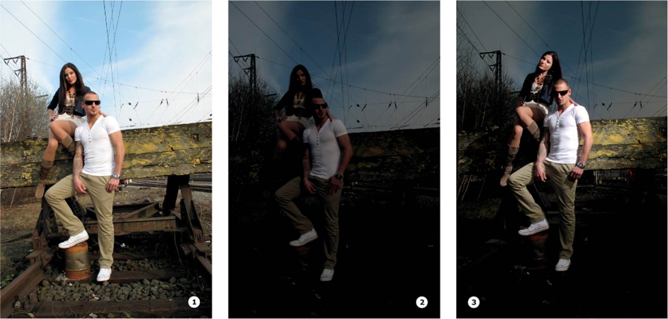
Left to right:
1 Canon PowerShot G10 in Av mode (no flash);
2 same as previous but underexposed by 2 stops;
3 with a YN-460 non-TTL flash attached with a spiral cable
Picture #3 f/4.5 | 1/2000 second | ISO 100 (Models: Cherryberry and Chris)
You may wonder why such short exposure times are needed. Various situations require this approach. For example, if you shoot with flash in direct sunlight, you usually have to set an exposure time longer than 1/200 second, and therefore, in return, you have to close the aperture down. However, this approach uses a lot of flash power, and you can’t use a wide aperture. One way around this problem is to use a neutral density (ND) filter, although it will adversely affect the image quality (see page 64).
The described HSS option can be a solution, but there are also drawbacks. The main disadvantage of HSS is that the overall amount of light is reduced by about two stops (with a Canon camera, the loss is –1.66 EV). Furthermore, for a long time HSS was feasible only in off-camera flash that is used along with the more expensive infrared or radio-controlled systems from your camera manufacturer, or the MiniTT1 and FlexTT5 models from PocketWizard. Cheaper radio trigger solutions now come from companies like Yongnuo (YN-622C/N) and Phottix (Odin TTL Flash Trigger) (see appendix A “Calculating HSS Exposure” on page 274).
Another possibility is to use a camera such as the Nikon D70 and the Canon EOS-1D, which have hybrid electromechanical shutters that make it possible to use extremely short flash sync speeds. Electronic leaf-type shutters are more widespread in compact cameras, such as the Canon PowerShot G9 and G10 models, which are capable of shooting at flash sync speeds as short as 1/4,000 second.
SuperSync or Pseudo-HSS (see page 54) is another way to produce similar effects. It involves using studio or portable flash heads set to high output (i.e., long flash duration) and setting the flash duration to be at least as long as the exposure time. In other words, the light from the flash unit shines the whole time the shutter is open. This technique requires a very responsive triggering system that is based on a dedicated system flash, as well as an optical servo slave trigger. The system flash has to be set to manual mode (to suppress the preflash) and HSS. It then triggers the optical servo, which then triggers a standard radio transmitter like the Yongnuo RF-602 (actually even a bit earlier). If the flash is set to a sufficiently high output setting, the flash duration will be longer than the exposure.
Interestingly, this technique can also be applied with low-cost accessory flash units without any TTL or HSS functionality. A Yongnuo YN-560 can, for example, be used at speeds shorter than the camera’s sync speed. However, the flash must be set to full output (to keep the flash duration as long as possible) and you will probably have to use several flashes in parallel to provide enough light. One disadvantage of this approach is the uneven brightness during the flash burning-off. Such imperfections can be repaired in Photoshop, but the problem can be serious enough to ruin an image—the trick is in the timing. This relatively new approach is gaining followers, so you can learn more by searching the Internet for “SuperSync,” “HyperSync,” “tail-sync hack,” and “strobist.”
First- and Second-Curtain Sync | If you take another look at the lower-left figure on page 25, you will see that there are various moments during the exposure when the flash can be fired. First-curtain sync fires the flash at t1 whereas second-curtain sync fires the flash at approximately t2minus the flash duration. Using second-curtain sync in combination with longer exposure times alters the look of the image, and the results are usually more in harmony with the viewer’s visual perception.
Most proprietary system flashes allow you to set first-or second-curtain sync in the menus of the camera or the flash unit, but it’s tricky when you use third-party gear. You can work around any restrictions by using an accessory flash to remotely trigger a second flash with its slave sensor. This allows you to shoot second-curtain (and SuperSync/pseudo-HSS) effects using studio flash. If you take this route, remember to switch the trigger flash to manual mode to suppress the preflash. Last but not least, if you aren’t convinced of the reliability of a slave sensor, place the slave trigger close to your flash and use it to trigger a radio transmitter. There is no end to the combinations you can use!
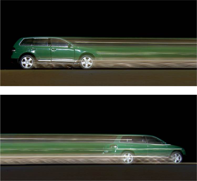
The car was moving from left to right in both photos. The top image demonstrates the sometimes implausible results of using first-curtain sync. The bottom image shows that second-curtain sync produces results that are more in line with our expectations.
All materials on the site are licensed Creative Commons Attribution-Sharealike 3.0 Unported CC BY-SA 3.0 & GNU Free Documentation License (GFDL)
If you are the copyright holder of any material contained on our site and intend to remove it, please contact our site administrator for approval.
© 2016-2026 All site design rights belong to S.Y.A.