Mastering the Olympus OM-D E-M1 (2015)
Control Location Reference
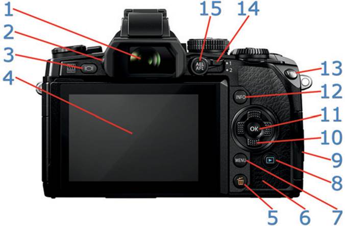
Figure 1: Back of camera body
1. Viewfinder (EVF)
2. Diopter adjustment dial
3. LV button
4. Monitor (Live view touch screen)
5. Erase button (Delete)
6. Speaker
7. MENU button
8. Playback button
9. Card slot cover (memory card)
10. Arrow Pad buttons
11. OK button
12. INFO button
13. Fn1 button
14. Lever
15. AEL/AFL button
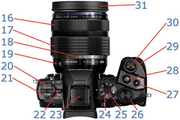
Figure 2: Top of camera body
16. Lens focus ring
17. Lens zoom ring
18. Lens zoom numbers (current focal length)
19. L-Fn button (only on certain lenses)
20. Sequential shooting/Self-timer/HDR button
21. AF/Metering mode button
22. On/Off lever
23. Hot shoe
24. Mode dial
25. Mode dial lock button
26. Rear dial
27. Movie button
28. Fn2 button
29. Front dial
30. Shutter button
31. Lens shade mount
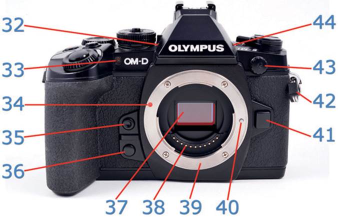
Figure 3: Front of camera body
32. Stereo microphone (right channel)
33. Self-timer lamp/AF illuminator
34. Lens attachment mark
35. One-touch white balance button
36. Preview button
37. Micro Four Thirds (4:3) Imaging Sensor (16 MP)
38. Lens electronic communication connectors
39. Lens bayonet mount
40. Lens lock pin
41. Lens release button
42. Strap eyelet
43. External flash connector (wired)
44. Stereo microphone (left channel)
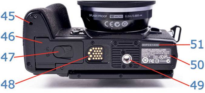
Figure 4: Bottom of camera body
45. Power battery holder (PBH) pin hole
46. Battery compartment cover
47. Battery compartment lock lever
48. Power battery holder electronic connectors (rubber cover removed)
49. Tripod socket
50. Camera ID plate
51. Serial number

Figure 5: Camera external connector ports
52. Microphone connector
53. HDMI connector (Type C)
54. Multi connector (USB)
55. Rubber covers (held open)
Colors and Wording Legend
Throughout this book, you’ll notice in the step-by-step instructions that there are colored terms as well as terms that are displayed in italic or bold font.
1. Blue is used to refer to the camera’s physical features.
2. Green is for functions and settings displayed on the camera’s screens.
3. Italic is for textual prompts seen on the camera’s LCD screens.
4. Italic or bold type is also used on select occasions for special emphasis.
Here is a sample paragraph with the colors and italic font in use:
Press the MENU button to open Shooting Menu 1, and then scroll to the Card Setup option by pressing the right Arrow pad button. Select Format and choose Yes from the menu. All images on Memory card will be deleted. Press the OK button to format the memory card. See page 131 in the Shooting Menu 1 chapter, under the Card Setup heading for deeper information.
With Card Setup highlighted, you can press the Info button to use the camera’s menu help system. The help system will inform you of the purpose of the Card Setup function, with the following explanation: Delete all pictures in the memory card or format the memory card.
All materials on the site are licensed Creative Commons Attribution-Sharealike 3.0 Unported CC BY-SA 3.0 & GNU Free Documentation License (GFDL)
If you are the copyright holder of any material contained on our site and intend to remove it, please contact our site administrator for approval.
© 2016-2026 All site design rights belong to S.Y.A.