3D Printing with SketchUp (2014)
Chapter 3. From 2D Drawing to 3D Model
One of the simplest kinds of 3D models starts from a simple drawing. Starting with pen and paper, a precise, professionally designed graphic or anything in between, you can quickly make a 3D-printable model. Logos and cookie cutters are some common 3D prints that are made from 2D graphics. In this chapter, we'll create a useful household object, starting from a simple hand-drawn sketch.
Starting from a quick sketch
For this exercise, let's start with something useful, and somewhat simple. But since we're going to 3D print it, we'll make a fun design.
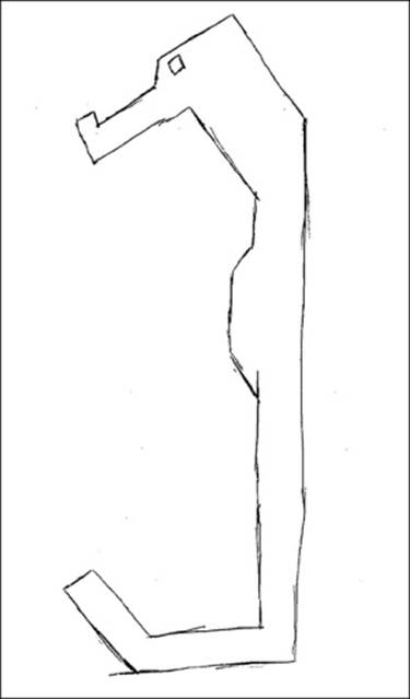
I started by making a pen and paper sketch of my initial concept—a hook-shaped, low-resolution version of a seahorse. I then scanned the image into a JPEG file and saved it to my computer. As you can see in the following figure, it's not a great drawing, but rather a starting point:
Designing for ease of printing
Let's talk about my thought process for this design. I intend for this hook to be printed on a desktop FFF printer. For that reason, I'm going to design parallel lines, no overhangs, and no tiny details. Although more complex designs are certainly printable, this will ensure an easy print from the start. Now, let's model!
Modeling in SketchUp from a sketch
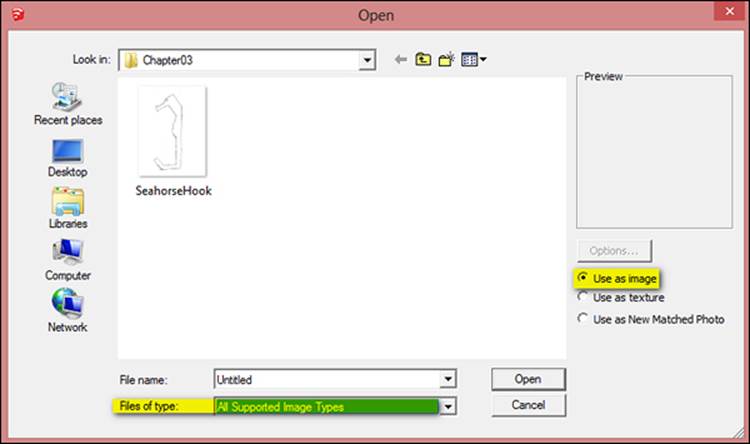
To get started, we need to import the image into SketchUp. Navigate to File | Import...; under Files of type, click on All Supported Image Types; and under Options, click on the Use as image radio button.
Double-click on the image or select the image and click on Open to close the Import dialog box, as shown in the following screenshot:
Click near the origin in SketchUp to set one corner of the image, and then move your cursor towards the upper-right side of the screen to set the size of the image. You want the image to be large enough to see but the exact scale isn't important now.
If you draw on the image right now, the SketchUp lines will be hard to see. Let's reduce the opacity of the image to make it easier to draw on. To do so, right-click on the image and click on Explode. Right away, double-click on the image to select it and its bounding edges, and then make it into a Group.
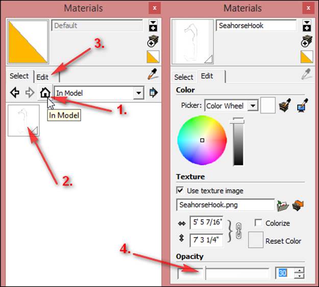
Open the Materials dialog box. Click on the home icon and then click on the In Model option. Now, select the imported image. Click on the Edit tab and drag the opacity slider down to around 30 percent as shown in the following screenshot:
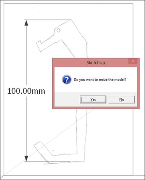
Now we'll scale the image to size. I want the printed hook to be 100 mm tall overall. For this step, the Tape Measure tool is fast and accurate. With Tape Measure, click on the top point of the seahorse's head, then the bottom flat edge of the hook. Immediately type100 mm and hit Enter. As shown in the following screenshot, SketchUp will ask, Do you want to resize the model?; click on Yes.
The model will scale to the correct size and may shift out of view. Use the Zoom Extents tool to center it back on the screen.
Now we're ready to begin drawing. Using the Line tool, trace the sketch, using the sketch as a rough guide, and not as an exact template. Because the sketch lines are probably not perfectly vertical and horizontal, be sure your horizontal and vertical lines in SketchUp align to the red and green axes, and not necessarily align exactly to the sketch.
Start at one point and work your way around the sketch, making sure each line is connected to the last one. Using the left and right arrow keys to lock to the green and red axes may help you at this point.
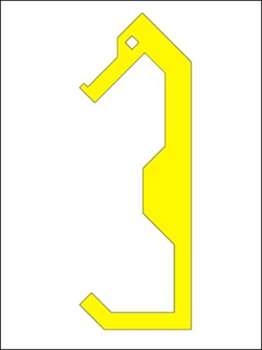
For the angled lines, I used the Protractor tool to create guides at 45 degrees, and traced over the guides. I used the Tape Measure tool to create guides for parallel lines. Before you move on to the next step, you should have a continuous outline that creates a face. Draw the eye last, then select and delete the interior face of the eye, as shown in the following figure:
Keeping a historical timeline of changes speeds iteration
Many of the products you use in your daily life are designed in a process where an idea is modeled, manufactured as a prototype, tested, analyzed, and then redesigned to improve functionality. This process of building a design and improving it over time is callediterative design, and each new model in the design is one iteration.
When you use a 3D printer to make the prototype, the process goes dramatically quicker, which is where the term rapid prototyping comes from. Saving a history of the models made during the design process is a good practice, so you know what changes have been made. One way to keep track of changes is by saving the file with a new version number, such as DesignV1 and DesignV2.
On a model as simple as this seahorse hook, I simply save copies of the new versions inside the original SketchUp model. Taking this idea one step further, I make copies at important stages of the model, even before one design is finished. This way, if you want to make changes to a part of the model when you're nearly finished, you can go back to an earlier stage of the model and work from there, rather than starting completely from scratch.
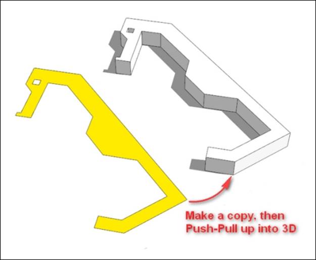
Let's apply this principle to our model now. Using the Move tool + CTRL, create a copy of the seahorse outline you just drew a few centimeters away. It's time to go 3D! Use the Push/Pull tool and extrude the copied face up. I chose a thickness of 8 mm, as shown in the following figure:
The original outline is still available to copy again, tweak the shape, and change it into an improved design, thereby saving the time it takes to trace the outline again.
Exporting the model and printing
Group the hook, verify that it's solid using the Entity Info dialog box, and you're ready to export it as an .STL file for 3D printing after following the steps outlined in Chapter 2, Setting Up SketchUp for 3D Printing.
If the group is not solid, look for interior faces, missing faces, or stray lines in the group. Interior faces and stray lines should be deleted, whereas missing faces need to be filled in. The Solid Inspector extension is an excellent tool for finding problems in this step. Refer to the Appendix, Resources for Your 3D Printing Success for more detailed information about troubleshooting models.
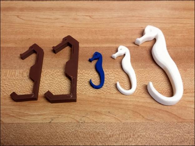
In the following screenshot, you can see several iterations of hooks that I 3D-printed starting from this exact model:
That completes this exercise. With a little practice, a small project like this will take you less than 15 minutes to go from the sketch to the printer.
Importing vector artwork
Sometimes artwork is available in vector format, having already been drawn in Illustrator or another 2D drawing program. In this case, you can save a lot of tedious tracing work by importing the drawing and using it as a base for your 3D model.
Tip
Vector graphics are different from the usual raster images we see that are made of pixels. Unlike raster images that look blurry when zoomed up close, vector graphics can be scaled, re-sized, and zoomed up without any loss of quality. Vector graphics describe the artwork in a way that SketchUp can interpret as lines, saving you from tracing the image manually. As an analogy, you can think of SketchUp models as 3D vector graphics.
In your 2D app, save the artwork as a .DXF file. You may need to add anchor points before exporting so that curves import smoothly. Please see the documentation for your vector graphics app for more info on how to add anchor points. SketchUp Pro natively imports .DWG and .DXF files. SketchUp Make imports .DXF with the Dxf_In plugin (http://sketchucation.com/forums/viewtopic.php?f=323&t=31186).
The import process doesn't always work perfectly. There may be tiny gaps between lines, short stray lines, or a variety of other problems. The Edge Tools² extension helps with those problems (https://extensions.sketchup.com/en/content/edge-tools²).
After importing, create faces inside the drawing outlines by tracing over an edge. For complex models, you may also use the Make Faces plugin to create the faces (http://www.smustard.com/script/MakeFaces).
At this point, you can pull the faces into 3D, and manipulate them just as with any other SketchUp geometry.
Changing the scale of the part
For printing in different sizes, you can use either the Scale tool or the Tape Measure tool just as you learned how to scale the image. The Scale tool works best for even increments such as 0.5 size or 3 times larger.
Sometimes you may want to scale along only one axis of a model. This is a job for the Scale tool. Learn how the various grips on the Scale tool affect the scaling of the model to quickly modify those parts.
The Tape Measure tool is a better choice when you know the exact dimensions (for example, 3.5 inches tall) and can measure directly on the part. With Tape Measure, pick any two points, and enter the desired dimension. The entire model will change scale uniformly. If you want to change just the scale of one group with Tape Measure, then open just that definition for editing and perform the scale operation. Only that group will change size and the rest of the model will remain the same size.
A bonus tip – the 45-degree overhang rule for filament printers
Filament printers perform best when overhangs are supported or are angled at 45 degrees or less. This is because the material must be deposited onto something, usually the layer below. You can see the difference as shown in the following figure:
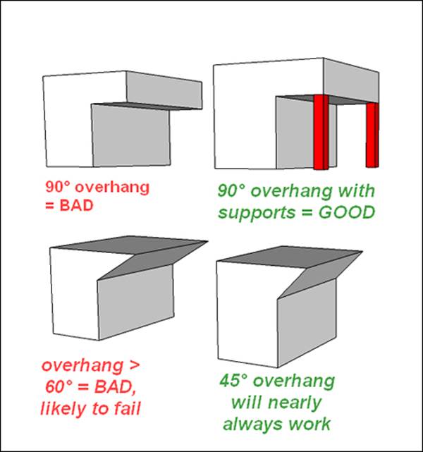
This leads to a common design rule called the "45-degree overhang rule". When designing for filament printers, keep the slope at 45 degrees or less for best results.
Bridging across a short distance (about 2-3 inches should be no problem) as shown in the preceding image, is also a viable solution, but the two sides must be of equal heights. The following figure shows how I added mounting holes for screws in the seahorse hook:
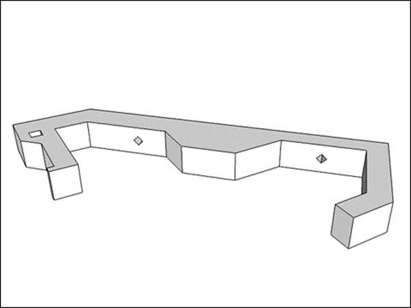
Notice how the holes are in a diamond shape so they meet the 45 degree overhang rule. Holes this small will actually print fine as circles as the filament will bridge the small gap, but for larger holes a diamond shape like this is a good idea.
Making the design your own
To take the design further, you can use the Arc tool or Roundcorner plugin to smooth out the sharp corners. You could cut a mounting hole at the back for a magnet, or add seahorse scales for decoration. How would you customize the design to make it your own?
Summary
In this chapter, you learned how to import an image and use the Tape Measure tool to scale your model. You learned to make a closed loop of edges to form a face, which may then be pulled up into a 3D shape. The Tape Measure and Protractor tools are useful for making guidelines to model accurately.
We discussed what iterative design is, and how to efficiently save copies of a model to create a history of changes.
Importing vector artwork created in a 2D drawing app can save you tedious drawing in SketchUp. Export the artwork as .DWG or .DXF to import into SketchUp.
We learned about the 45-degree rule when designing for filament printers. Keeping overhangs to 45 degrees or less results in the best prints. Bridging short distances is also viable when the two sides are of equal height. These principles are discussed further inChapter 6, Designing a Phone Cradle.