Introduction to 3D Game Programming with DirectX 12 (Computer Science) (2016)
|
Part 3 |
TOPICS
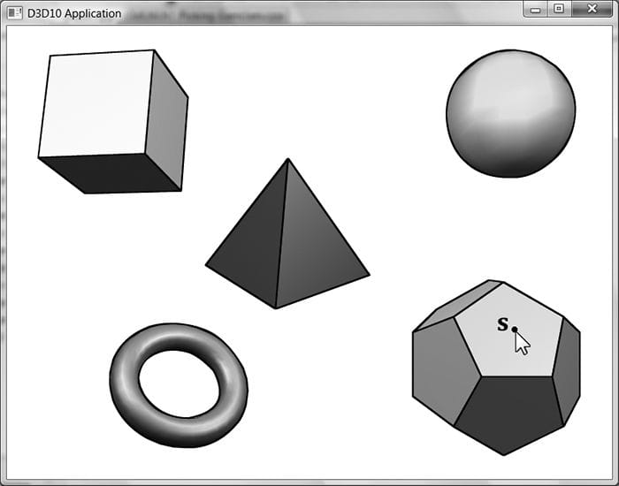
In this chapter, we have the problem of determining the 3D object (or primitive) the user picked with the mouse cursor (see Figure 17.1). In other words, given the 2D screen coordinates of the mouse cursor, can we determine the 3D object that was projected onto that point? To solve this problem, in some sense, we must work backwards; that is to say, we typically transform from 3D space to screen space, but here we transform from screen space back to 3D space. Of course, we already have a slight problem: a 2D screen point does not correspond to a unique 3D point (i.e., more than one 3D point could be projected onto the same 2D projection window point—see Figure 17.2). Thus, there is some ambiguity in determining which object is really picked. However, this is not such a big problem, as the closest object to the camera is usually the one we want.
Figure 17.1. The user picking the dodecahedron.
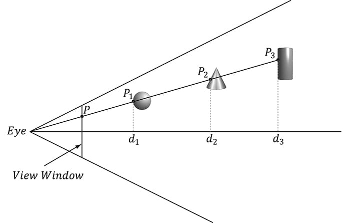
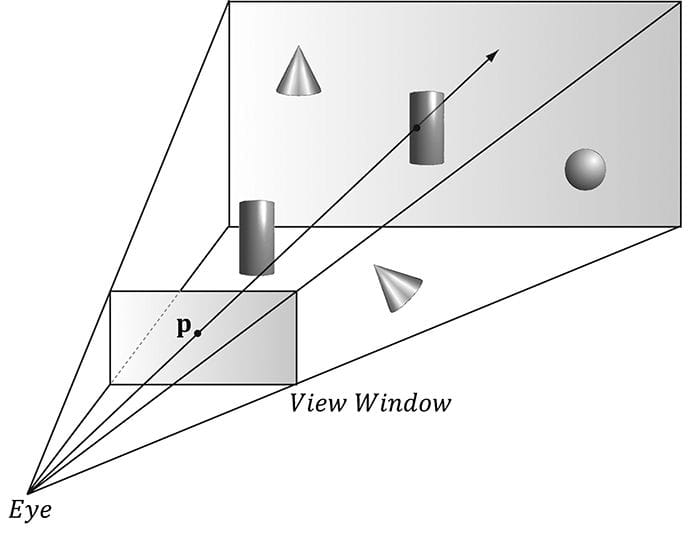
Figure 17.2. A side view of the frustum. Observe that several points in 3D space can get projected onto a point on the projection window. Consider Figure 17.3, which shows the viewing frustum. Here p is the point on the projection window that corresponds to the clicked screen point s. Now, we see that if we shoot a picking ray, originating at the eye position, through p, we will intersect the object whose projection surrounds p, namely the cylinder in this example. Therefore, our strategy is as follows: Once we compute the picking ray, we can iterate through each object in the scene and test if the ray intersects it. The object that the ray intersects is the object that was picked by the user. As mentioned, the ray may intersect several scene objects (or none at all—nothing was picked), if the objects are along the ray’s path but with different depth values, for example. In this case, we can just take the intersected object nearest to the camera as the picked object.
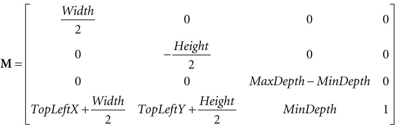
Figure 17.3. A ray shooting through p will intersect the object whose projection surrounds p. Note that the projected point p on the projection window corresponds to the clicked screen point s. Objectives: 1. To learn how to implement the picking algorithm and to understand how it works. We break picking down into the following four steps: 1. Given the clicked screen point s, find its corresponding point on the projection window and call it p. 2. Compute the picking ray in view space. That is the ray originating at the origin, in view space, which shoots through p. 3. Transform the picking ray and the models to be tested with the ray into the same space. 4. Determine the object the picking ray intersects. The nearest (from the camera) intersected object corresponds to the picked screen object. 17.1 SCREEN TO PROJECTION WINDOW TRANSFORM The first task is to transform the clicked screen point to normalized device coordinates (see §5.4.3.3). Recall that the viewport matrix transforms vertices from normalized device coordinates to screen space; it is given below:
The variables of the viewport matrix refer to those of the D3D12_VIEWPORT structure: typedef struct D3D12_VIEWPORT { FLOAT TopLeftX; FLOAT TopLeftY; FLOAT Width; FLOAT Height; FLOAT MinDepth; FLOAT MaxDepth; } D3D12_VIEWPORT; Generally, for a game, the viewport is the entire backbuffer and the depth buffer range is 0 to 1. Thus, TopLeftX = 0, TopLeftY = 0, MinDepth = 0, MaxDepth = 1, Width = w, and Height = h, where w and h, are the width and height of the backbuffer, respectively. Assuming this is indeed the case, the viewport matrix simplifies to:
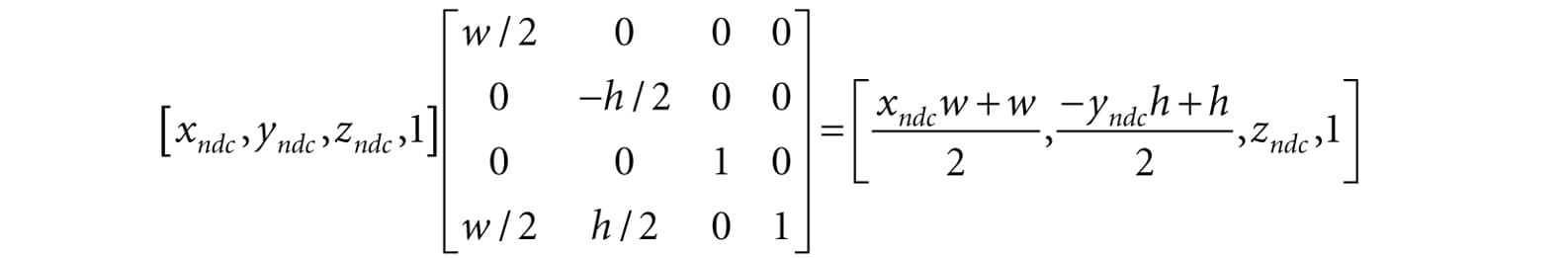
Now let pndc = (xndc, yndc, zndc, 1) be a point in normalized device space (i.e., −1 ≤ xndc ≤ 1, −1 ≤ yndc ≤ 1, and 0 ≤ zndc ≤ 1). Transforming pndc to screen space yields:
The coordinate zndc is just used by the depth buffer and we are not concerned with any depth coordinates for picking. The 2D screen point ps = (xs, ys) corresponding to pndc is just the transformed x- and y-coordinates:
The above equation gives us the screen point ps in terms of the normalized device point pndc and the viewport dimensions. However, in our picking situation, we are initially given the screen point ps and the viewport dimensions, and we want to find pndc. Solving the above equations for pndc yields:
We now have the clicked point in NDC space. But to shoot the picking ray, we really want the screen point in view space. Recall from §5.6.3.3 that we mapped the projected point from view space to NDC space by dividing the x-coordinate by the aspect ratio r:
Thus, to get back to view space, we just need to multiply the x-coordinate in NDC space by the aspect ratio. The clicked point in view space is thus:
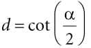
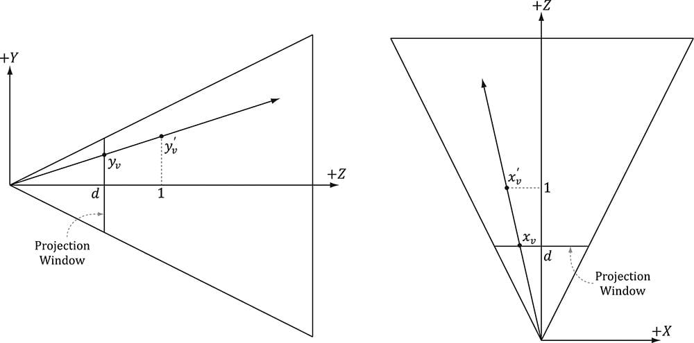
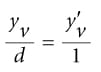
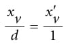
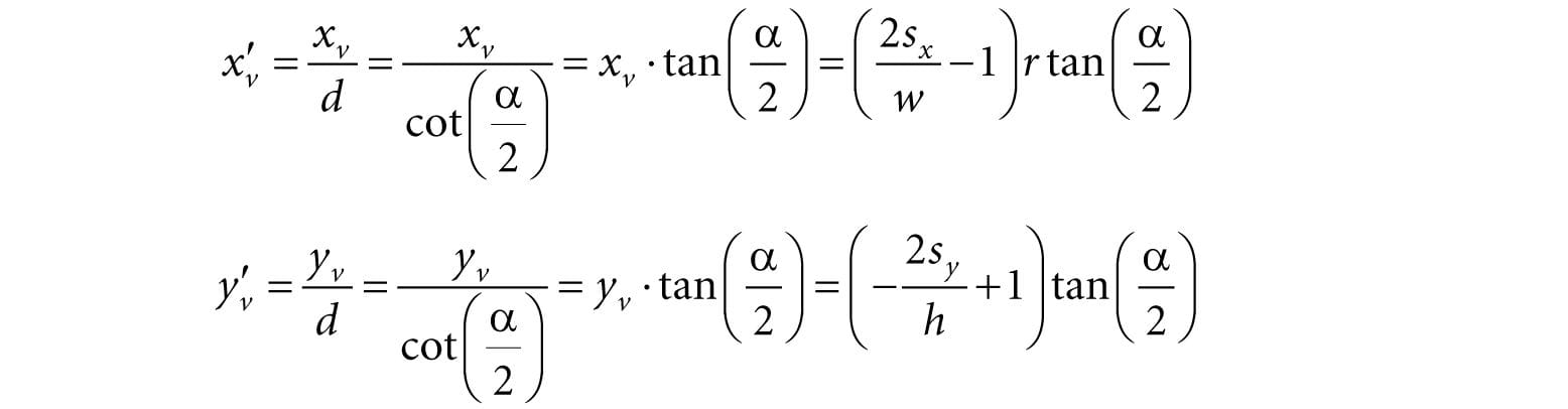
Now recall from §5.6.3.1 that the projection window lies at a distance from the origin, where α is the vertical field of view angle. So we could shoot the picking ray through the point (xv, yv, d ) on the projection window. However, this requires that we compute . A simpler way is to observe from Figure 17.4 that:
Figure 17.4. By similar triangles, and .
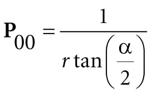
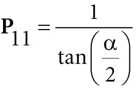
Recalling that and in the projection matrix, we can rewrite this as:
Thus, we can shoot our picking ray through the point (x′v, y′v, 1) instead. Note that this yields the same picking ray as the one shot through the point (xv, yv, d). The code that computes the picking ray in view space is given below: void PickingApp::Pick(int sx, int sy) { XMFLOAT4X4 P = mCamera.GetProj4x4f(); // Compute picking ray in view space. float vx = (+2.0f*sx / mClientWidth - 1.0f) / P(0, 0); float vy = (-2.0f*sy / mClientHeight + 1.0f) / P(1, 1); // Ray definition in view space. XMVECTOR rayOrigin = XMVectorSet(0.0f, 0.0f, 0.0f, 1.0f); XMVECTOR rayDir = XMVectorSet(vx, vy, 1.0f, 0.0f); Note that the ray originates from the origin in view space since the eye sits at the origin in view space. 17.2 WORLD/LOCAL SPACE PICKING RAY So far we have the picking ray in view space, but this is only useful if our objects are in view space as well. Because the view matrix transforms geometry from world space to view space, the inverse of the view matrix transforms geometry from view space to world space. If rv(t) = q + tu is the view space picking ray and V is the view matrix, then the world space picking ray is given by:
Note that the ray origin q is transformed as a point (i.e., qw = 1) and the ray direction u is transformed as a vector (i.e., uw = 0). A world space picking ray can be useful in some situations where you have some objects defined in world space. However, most of the time, the geometry of an object is defined relative to the object’s own local space. Therefore, to perform the ray/object intersection test, we must transform the ray into the local space of the object. If W is the world matrix of an object, the matrix W−1 transforms geometry from world space to the local space of the object. Thus the local space picking ray is:
Generally, each object in the scene has its own local space. Therefore, the ray must be transformed to the local space of each scene object to do the intersection test. One might suggest transforming the meshes to world space and doing the intersection test there. However, this is too expensive. A mesh may contain thousands of vertices, and all those vertices would need to be transformed to world space. It is much more efficient to just transform the ray to the local spaces of the objects. The following code shows how the picking ray is transformed from view space to the local space of an object: // Assume nothing is picked to start, so the picked render-item is invisible. mPickedRitem->Visible = false; // Check if we picked an opaque render item. A real app might keep a separate // "picking list" of objects that can be selected. for(auto ri : mRitemLayer[(int)RenderLayer::Opaque]) { auto geo = ri->Geo; // Skip invisible render-items. if(ri->Visible == false) continue; XMMATRIX V = mCamera.GetView(); XMMATRIX invView = XMMatrixInverse(&XMMatrixDeterminant(V), V); XMMATRIX W = XMLoadFloat4x4(&ri->World); XMMATRIX invWorld = XMMatrixInverse(&XMMatrixDeterminant(W), W); // Tranform ray to vi space of Mesh. XMMATRIX toLocal = XMMatrixMultiply(invView, invWorld); rayOrigin = XMVector3TransformCoord(rayOrigin, toLocal); rayDir = XMVector3TransformNormal(rayDir, toLocal); // Make the ray direction unit length for the intersection tests. rayDir = XMVector3Normalize(rayDir); The XMVector3TransformCoord and XMVector3TransformNormal functions take 3D vectors as parameters, but note that with the XMVector3TransformCoord function there is an understood w = 1 for the fourth component. On the other hand, with the XMVector3TransformNormal function there is an understood w = 0 for the fourth component. Thus we can use XMVector3TransformCoord to transform points and we can use XMVector3TransformNormal to transform vectors. 17.3 RAY/MESH INTERSECTION Once we have the picking ray and a mesh in the same space, we can perform the intersection test to see if the picking ray intersects the mesh. The following code iterates through each triangle in the mesh and does a ray/triangle intersection test. If the ray intersects one of the triangles, then it must have hit the mesh the triangle belongs to. Otherwise, the ray misses the mesh. Typically, we want the nearest triangle intersection, as it is possible for a ray to intersect several mesh triangles if the triangles overlap with respect to the ray. // If we hit the bounding box of the Mesh, then we might have // picked a Mesh triangle, so do the ray/triangle tests. // // If we did not hit the bounding box, then it is impossible that we hit // the Mesh, so do not waste effort doing ray/triangle tests. float tmin = 0.0f; if(ri->Bounds.Intersects(rayOrigin, rayDir, tmin)) { // NOTE: For the demo, we know what to cast the vertex/index data to. // If we were mixing formats, some metadata would be needed to figure // out what to cast it to. auto vertices = (Vertex*)geo->VertexBufferCPU->GetBufferPointer(); auto indices = (std::uint32_t*)geo->IndexBufferCPU->GetBufferPointer(); UINT triCount = ri->IndexCount / 3; // Find the nearest ray/triangle intersection. tmin = MathHelper::Infinity; for(UINT i = 0; i < triCount; ++i) { // Indices for this triangle. UINT i0 = indices[i * 3 + 0]; UINT i1 = indices[i * 3 + 1]; UINT i2 = indices[i * 3 + 2]; // Vertices for this triangle. XMVECTOR v0 = XMLoadFloat3(&vertices[i0].Pos); XMVECTOR v1 = XMLoadFloat3(&vertices[i1].Pos); XMVECTOR v2 = XMLoadFloat3(&vertices[i2].Pos); // We have to iterate over all the triangles in order to find // the nearest intersection. float t = 0.0f; if(TriangleTests::Intersects(rayOrigin, rayDir, v0, v1, v2, t)) { if(t < tmin) { // This is the new nearest picked triangle. tmin = t; UINT pickedTriangle = i; // Set a render item to the picked triangle so that // we can render it with a special "highlight" material. mPickedRitem->Visible = true; mPickedRitem->IndexCount = 3; mPickedRitem->BaseVertexLocation = 0; // Picked render item needs same world matrix as object picked. mPickedRitem->World = ri->World; mPickedRitem->NumFramesDirty = gNumFrameResources; // Offset to the picked triangle in the mesh index buffer. mPickedRitem->StartIndexLocation = 3 * pickedTriangle; } } } } Observe that for picking, we use the system memory copy of the mesh geometry stored in the MeshGeometry class. This is because we cannot access a vertex/index buffer for reading that is going to be drawn by the GPU. It is common to store system memory copies of geometry for things like picking and collision detection. Sometimes a simplified version of the mesh is stored for these purposes to save memory and computation. 17.3.1 Ray/AABB Intersection Observe that we first use the DirectX collision library function BoundingBox:: Intersects to see if the ray intersects the bounding box of the mesh. This is analogous to the frustum culling optimization in the previous chapter. Performing a ray intersection test for every triangle in the scene adds up in computation time. Even for meshes not near the picking ray, we would still have to iterate over each triangle to conclude the ray misses the mesh; this is wasteful and inefficient. A popular strategy is to approximate the mesh with a simple bounding volume, like a sphere or box. Then, instead of intersecting the ray with the mesh, we first intersect the ray with the bounding volume. If the ray misses the bounding volume, then the ray necessarily misses the triangle mesh and so there is no need to do further calculations. If the ray intersects the bounding volume, then we do the more precise ray/mesh test. Assuming that the ray will miss most bounding volumes in the scene, this saves us many ray/triangle intersection tests. The BoundingBox::Intersects function returns true if the ray intersects the box and false otherwise; it is prototyped as follows: bool XM_CALLCONV BoundingBox::Intersects( FXMVECTOR Origin, // ray origin FXMVECTOR Direction, // ray direction (must be unit length) float& Dist ); const // ray intersection parameter Given the ray r(t) = q + tu, the last parameter outputs the ray parameter t0 that yields the actual intersection point p:
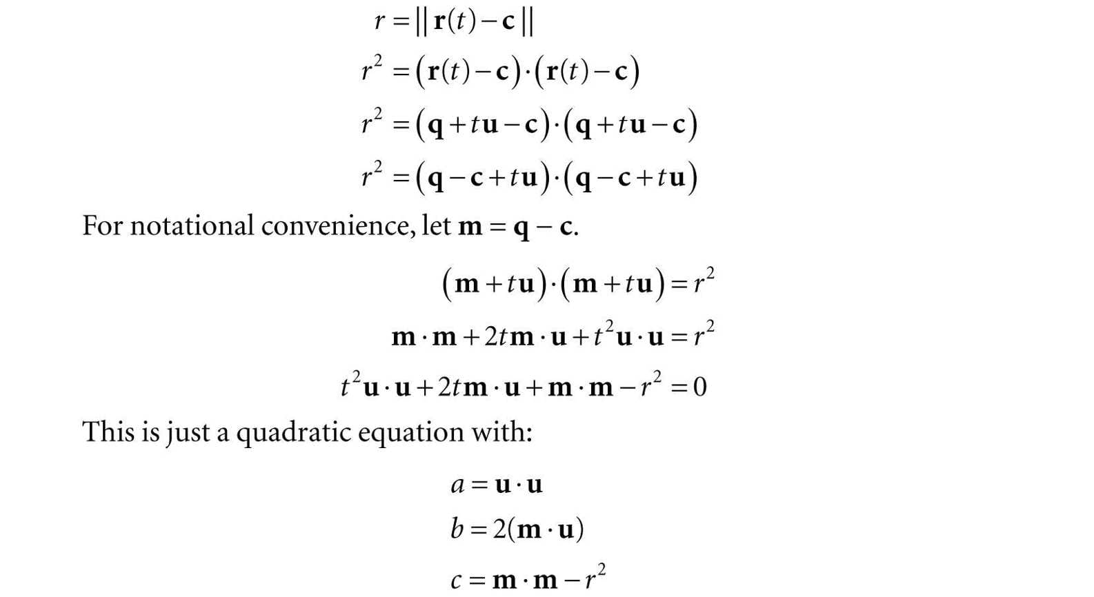
17.3.2 Ray/Sphere Intersection There is also a ray/sphere intersection test given in the DirectX collision library: bool XM_CALLCONV BoundingSphere::Intersects( FXMVECTOR Origin, FXMVECTOR Direction, float& Dist ); const To give a flavor of these tests, we show how to derive the ray/sphere intersection test. The points p on the surface of a sphere with center c and radius r satisfy the equation:
Let r(t) = q + tu be a ray. We wish to solve for t1 and t2 such that r(t1) and r(t2) satisfy the sphere equation (i.e., the parameters t1 and t2 along the ray that yields the intersection points).
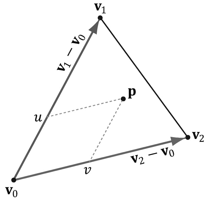
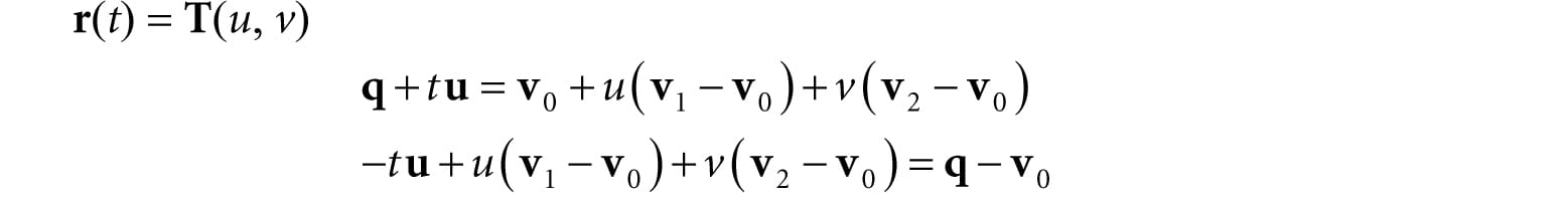
If the ray direction is unit length, then a = u · u =1. If the solution has imaginary components, the ray misses the sphere. If the two real solutions are the same, the ray intersects a point tangent to the sphere. If the two real solutions are distinct, the ray pierces two points of the sphere. A negative solution indicates an intersection point “behind” the ray. The smallest positive solution gives the nearest intersection parameter. 17.3.3 Ray/Triangle Intersection For performing a ray/triangle intersection test, we use the DirectX collision library function TriangleTests::Intersects: bool XM_CALLCONV TriangleTests::Intersects( FXMVECTOR Origin, // ray origin FXMVECTOR Direction, // ray direction (unit length) FXMVECTOR V0, // triangle vertex v0 GXMVECTOR V1, // triangle vertex v1 HXMVECTOR V2, // triangle vertex v2 float& Dist ); // ray intersection parameter Let r(t) = q + tu be a ray and T(u, v) = v0 + u(v1 – v0) + v(v2 – v0) for u ≥ 0, v ≥ 0, u + v ≤ 1 be a triangle (see Figure 17.5). We wish to simultaneously solve for t, u, v such that r(t) = T(u, v) (i.e., the point the ray and triangle intersect):
Figure 17.5. The point p in the plane of the triangle has coordinates (u, v) relative to the skewed coordinate system with origin v0 and axes v1 − v0 and v2 − v0.
For notational convenience, let e1 = v1 − v0, e2 = v2 − v0 and m = q − v0
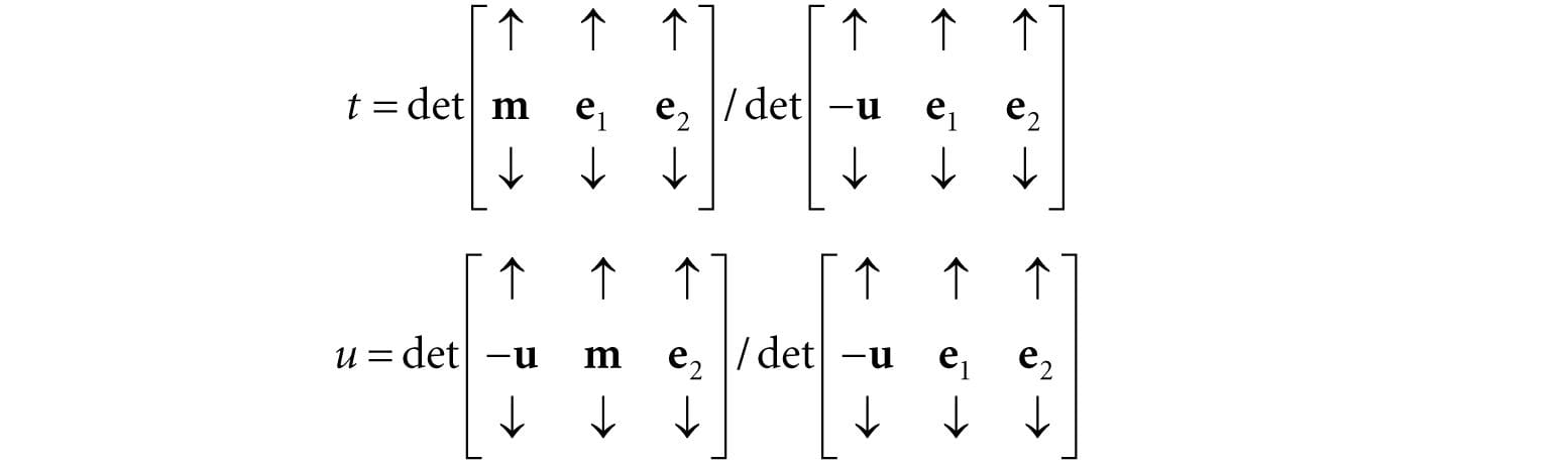
Consider the matrix equation Ax = b, where A is invertible. Then Cramer’s Rule tells us that xi = det Ai/det A, where Ai is found by swapping the ith column vector in A with b. Therefore,
Using the fact that we can reformulate this as:
To optimize the computations a bit, we can use the fact that every time we swap columns in a matrix, the sign of the determinant changes:
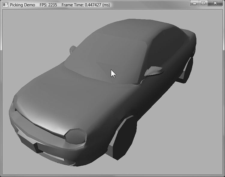
And note the common cross products that can be reused in the calculations: m × e1 and u × e2. 17.4 DEMO APPLICATION The demo for this chapter renders a car mesh and allows the user to pick a triangle by pressing the right mouse button, and the selected triangle is rendered using a “highlight” material (see Figure 17.6). To render the triangle with a highlight, we need a render-item for it. Unlike the previous render-items in this book where we defined them at initialization time, this render-item can only be partially filled out at initialization time. This is because we do not yet know which triangle will be picked, and so we do not know the starting index location and world matrix. In addition, a triangle does not need to always be picked. Therefore, we have added a Visible property to the render-item structure. An invisible render-item will not be drawn. The below code, which is part of the PickingApp::Pick method, shows how we fill out the remaining render-item properties based on the selected triangle:
Figure 17.6. The picked triangle is highlighted green. // Cache a pointer to the render-item of the picked // triangle in the PickingApp class. RenderItem* mPickedRitem; if(TriangleTests::Intersects(rayOrigin, rayDir, v0, v1, v2, t)) { if(t < tmin) { // This is the new nearest picked triangle. tmin = t; UINT pickedTriangle = i; // Set a render item to the picked triangle so that // we can render it with a special "highlight" material. mPickedRitem->Visible = true; mPickedRitem->IndexCount = 3; mPickedRitem->BaseVertexLocation = 0; // Picked render item needs same world matrix as object picked. mPickedRitem->World = ri->World; mPickedRitem->NumFramesDirty = gNumFrameResources; // Offset to the picked triangle in the mesh index buffer. mPickedRitem->StartIndexLocation = 3 * pickedTriangle; } } This render-item is drawn after we draw our opaque render-items. It uses a special highlight PSO, which uses transparency blending and sets the depth test comparison function to D3D12_COMPARISON_FUNC_LESS_EQUAL. This is needed because the picked triangle will be drawn twice, the second time with the highlighted material. The second time the triangle is drawn the depth test would fail if the comparison function was just D3D12_COMPARISON_FUNC_LESS. DrawRenderItems(mCommandList.Get(), mRitemLayer[(int)RenderLayer::Opaque]); mCommandList->SetPipelineState(mPSOs["highlight"].Get()); DrawRenderItems(mCommandList.Get(), mRitemLayer[(int)RenderLayer::Highlight]); 17.5 SUMMARY 1. Picking is the technique used to determine the 3D object that corresponds to the 2D projected object displayed on the screen that the user clicked on with the mouse. 2. The picking ray is found by shooting a ray, originating at the origin of the view space, through the point on the projection window that corresponds to the clicked screen point. 3. We can transform a ray r(t) = q + tu by transforming its origin q and direction u by a transformation matrix. Note that the origin is transformed as a point (w = 1) and the direction is treated as a vector (w = 0). 4. To test if a ray has intersected an object, we perform a ray/triangle intersection test for every triangle in the object. If the ray intersects one of the triangles, then it must have hit the mesh the triangle belongs to. Otherwise, the ray misses the mesh. Typically, we want the nearest triangle intersection, as it is possible for a ray to intersect several mesh triangles if the triangles overlap with respect to the ray. 5. A performance optimization for ray/mesh intersection tests is to first perform an intersection test between the ray and a bounding volume that approximates the mesh. If the ray misses the bounding volume, then the ray necessarily misses the triangle mesh and so there is no need to do further calculations. If the ray intersects the bounding volume, then we do the more precise ray/mesh test. Assuming that the ray will miss most bounding volumes in the scene, this saves us many ray/triangle intersection tests. 17.6 EXERCISES 1. Modify the “Picking” demo to use a bounding sphere for the mesh instead of an AABB. 2. Research the algorithm for doing a ray/AABB intersection test. 3. If you had thousands of objects in a scene, you would still have to do thousands of ray/bounding volume tests for picking. Research octrees, and explain how they can be used to reduce ray/bounding volume intersection tests. Incidentally, the same general strategy works for reducing frustum/bounding volume intersection tests for frustum culling. All materials on the site are licensed Creative Commons Attribution-Sharealike 3.0 Unported CC BY-SA 3.0 & GNU Free Documentation License (GFDL) If you are the copyright holder of any material contained on our site and intend to remove it, please contact our site administrator for approval. © 2016-2026 All site design rights belong to S.Y.A. |