Introduction to 3D Game Programming with DirectX 12 (Computer Science) (2016)
|
Part 2 |
DIRECT3D
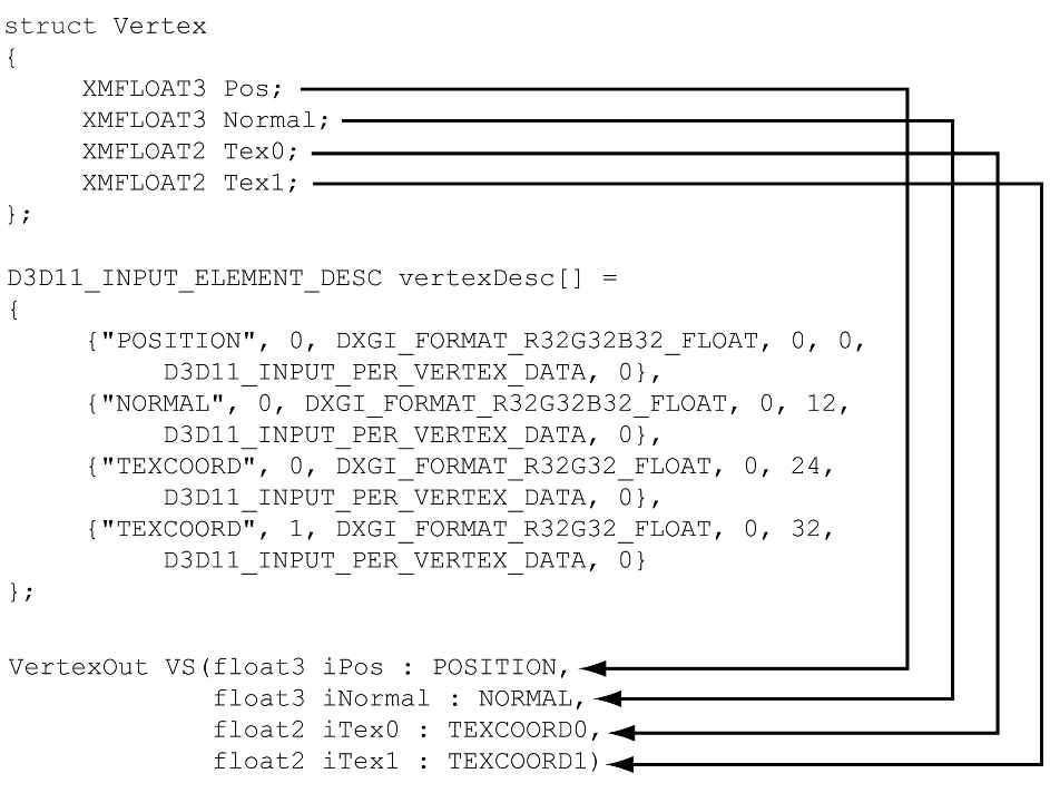
In the previous chapter, we mostly focused on the conceptual and mathematical aspects of the rendering pipeline. This chapter, in turn, focuses on the Direct3D API interfaces and methods needed to configure the rendering pipeline, define vertex and pixel shaders, and submit geometry to the rendering pipeline for drawing. By the end of this chapter, you will be able to draw a 3D box with solid coloring or in wireframe mode. Objectives: 1. To discover the Direct3D interfaces methods for defining, storing, and drawing geometric data. 2. To learn how to write basic vertex and pixel shaders. 3. To find out how to configure the rendering pipeline with pipeline state objects. 4. To understand how to create and bind constant buffer data to the pipeline, and to become familiar with the root signature. 6.1 VERTICES AND INPUT LAYOUTS Recall from §5.5.1 that a vertex in Direct3D can consist of additional data besides spatial location. To create a custom vertex format, we first create a structure that holds the vertex data we choose. For instance, the following illustrates two different kinds of vertex formats; one consists of position and color, and the second consists of position, normal vector, and two sets of 2D texture coordinates. struct Vertex1 { XMFLOAT3 Pos; XMFLOAT4 Color; }; struct Vertex2 { XMFLOAT3 Pos; XMFLOAT3 Normal; XMFLOAT2 Tex0; XMFLOAT2 Tex1; }; Once we have defined a vertex structure, we need to provide Direct3D with a description of our vertex structure so that it knows what to do with each component. This description is provided to Direct3D in the form of an input layout description which is represented by the D3D12_INPUT_LAYOUT_DESC structure: typedef struct D3D12_INPUT_LAYOUT_DESC { const D3D12_INPUT_ELEMENT_DESC *pInputElementDescs; UINT NumElements; } D3D12_INPUT_LAYOUT_DESC; An input layout description is simply an array of D3D12_INPUT_ELEMENT_DESC elements, and the number of elements in the array. Each element in the D3D12_INPUT_ELEMENT_DESC array describes and corresponds to one component in the vertex structure. So if the vertex structure has two components, then the corresponding D3D12_INPUT_ELEMENT_DESC array will have two elements. The D3D12_INPUT_ELEMENT_DESC structure is defined as: typedef struct D3D12_INPUT_ELEMENT_DESC { LPCSTR SemanticName; UINT SemanticIndex; DXGI_FORMAT Format; UINT InputSlot; UINT AlignedByteOffset; D3D12_INPUT_CLASSIFICATION InputSlotClass; UINT InstanceDataStepRate; } D3D12_INPUT_ELEMENT_DESC; 1. SemanticName: A string to associate with the element. This can be any valid variable name. Semantics are used to map elements in the vertex structure to elements in the vertex shader input signature; see Figure 6.1.
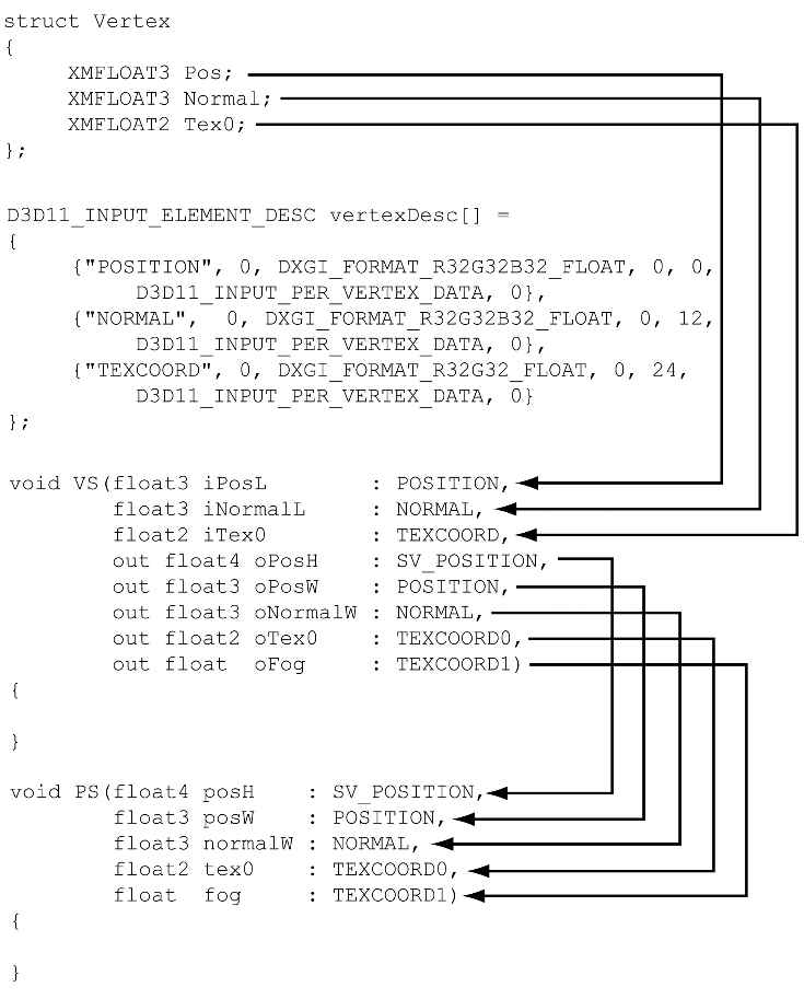
Figure 6.1. Each element in the vertex structure is described by a corresponding element in the D3D12_INPUT_ELEMENT_DESC array. The semantic name and index provides way for mapping vertex elements to the corresponding parameters of the vertex shader. 2. SemanticIndex: An index to attach to a semantic. The motivation for this is illustrated in Figure 6.1, where, for example, a vertex structure may have more than one set of texture coordinates; so rather than introducing a new semantic name, we can just attach an index to the end to distinguish the two texture coordinate sets. A semantic with no index specified in the shader code defaults to index zero; for instance, POSITION is equivalent to POSITION0 in Figure 6.1. 3. Format: A member of the DXGI_FORMAT enumerated type specifying the format (i.e., the data type) of this vertex element to Direct3D; here are some common examples of formats used: DXGI_FORMAT_R32_FLOAT // 1D 32-bit float scalar DXGI_FORMAT_R32G32_FLOAT // 2D 32-bit float vector DXGI_FORMAT_R32G32B32_FLOAT // 3D 32-bit float vector DXGI_FORMAT_R32G32B32A32_FLOAT // 4D 32-bit float vector DXGI_FORMAT_R8_UINT // 1D 8-bit unsigned integer scalar DXGI_FORMAT_R16G16_SINT // 2D 16-bit signed integer vector DXGI_FORMAT_R32G32B32_UINT // 3D 32-bit unsigned integer vector DXGI_FORMAT_R8G8B8A8_SINT // 4D 8-bit signed integer vector DXGI_FORMAT_R8G8B8A8_UINT // 4D 8-bit unsigned integer vector 4. InputSlot: Specifies the input slot index this element will come from. Direct3D supports sixteen input slots (indexed from 0-15) through which you can feed vertex data. For now, we will only be using input slot 0 (i.e., all vertex elements come from the same input slot); Exercise 2 asks you to experiment with multiple input slots. 5. AlignedByteOffset: The offset, in bytes, from the start of the C++ vertex structure of the specified input slot to the start of the vertex component. For example, in the following vertex structure, the element Pos has a 0-byte offset since its start coincides with the start of the vertex structure; the element Normal has a 12-byte offset because we have to skip over the bytes of Pos to get to the start of Normal; the element Tex0 has a 24-byte offset because we need to skip over the bytes of Pos and Normal to get to the start of Tex0; the element Tex1 has a 32-byte offset because we need to skip over the bytes of Pos, Normal, and Tex0 to get to the start of Tex1. struct Vertex2 { XMFLOAT3 Pos; // 0-byte offset XMFLOAT3 Normal; // 12-byte offset XMFLOAT2 Tex0; // 24-byte offset XMFLOAT2 Tex1; // 32-byte offset }; 6. InputSlotClass: Specify D3D12_INPUT_PER_VERTEX_DATA for now; the other option is used for the advanced technique of instancing. 7. InstanceDataStepRate: Specify 0 for now; other values are only used for the advanced technique of instancing. For the previous two example vertex structures, Vertex1 and Vertex2, the corresponding input layout descriptions would be: D3D12_INPUT_ELEMENT_DESC desc1[] = { {"POSITION", 0, DXGI_FORMAT_R32G32B32_FLOAT, 0, 0, D3D12_INPUT_PER_VERTEX_DATA, 0}, {"COLOR", 0, DXGI_FORMAT_R32G32B32A32_FLOAT, 0, 12, D3D12_INPUT_PER_VERTEX_DATA, 0} }; D3D12_INPUT_ELEMENT_DESC desc2[] = { {"POSITION", 0, DXGI_FORMAT_R32G32B32_FLOAT, 0, 0, D3D12_INPUT_PER_VERTEX_DATA, 0}, {"NORMAL", 0, DXGI_FORMAT_R32G32B32_FLOAT, 0, 12, D3D12_INPUT_PER_VERTEX_DATA, 0}, {"TEXCOORD", 0, DXGI_FORMAT_R32G32_FLOAT, 0, 24, D3D12_INPUT_PER_VERTEX_DATA, 0} {"TEXCOORD", 1, DXGI_FORMAT_R32G32_FLOAT, 0, 32, D3D12_INPUT_PER_VERTEX_DATA, 0} }; 6.2 VERTEX BUFFERS In order for the GPU to access an array of vertices, they need to be placed in a GPU resource (ID3D12Resource) called a buffer. We call a buffer that stores vertices a vertex buffer. Buffers are simpler resources than textures; they are not multidimensional, and do not have mipmaps, filters, or multisampling support. We will use buffers whenever we need to provide the GPU with an array of data elements such as vertices. As we did in §4.3.8, we create an ID3D12Resource object by filling out a D3D12_RESOURCE_DESC structure describing the buffer resource, and then calling the ID3D12Device::CreateCommittedResource method. See §4.3.8 for a description of all the members of the D3D12_RESOURCE_DESC structure. Direct3D 12 provides a C++ wrapper class CD3DX12_RESOURCE_DESC, which derives from D3D12_RESOURCE_DESC and provides convenience constructors and methods. In particular, it provides the following method that simplifies the construction of a D3D12_RESOURCE_DESC describing a buffer: static inline CD3DX12_RESOURCE_DESC Buffer( UINT64 width, D3D12_RESOURCE_FLAGS flags = D3D12_RESOURCE_FLAG_NONE, UINT64 alignment = 0 ) { return CD3DX12_RESOURCE_DESC( D3D12_RESOURCE_DIMENSION_BUFFER, alignment, width, 1, 1, 1, DXGI_FORMAT_UNKNOWN, 1, 0, D3D12_TEXTURE_LAYOUT_ROW_MAJOR, flags ); } For a buffer, the width refers to the number of bytes in the buffer. For example, if the buffer stored 64 floats, then the width would be 64*sizeof(float).
1. CD3DX12_RESOURCE_DESC::Tex1D 2. CD3DX12_RESOURCE_DESC::Tex2D 3. CD3DX12_RESOURCE_DESC::Tex3D
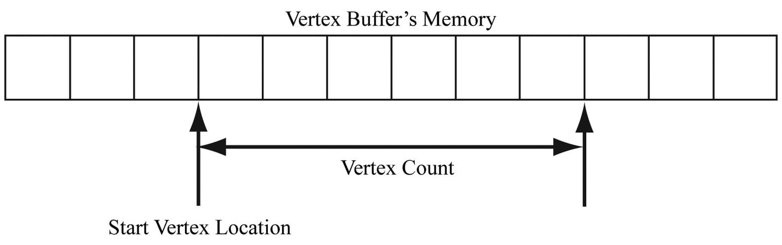
For static geometry (i.e., geometry that does not change on a per-frame basis), we put vertex buffers in the default heap (D3D12_HEAP_TYPE_DEFAULT) for optimal performance. Generally, most geometry in a game will be like this (e.g., trees, buildings, terrain, characters). After the vertex buffer has been initialized, only the GPU needs to read from the vertex buffer to draw the geometry, so the default heap makes sense. However, if the CPU cannot write to the vertex buffer in the default heap, how do we initialize the vertex buffer? In addition to creating the actual vertex buffer resource, we need to create an intermediate upload buffer resource with heap type D3D12_HEAP_TYPE_UPLOAD. Recall from §4.3.8 that we commit a resource to the upload heap when we need to copy data from CPU to GPU memory. After we create the upload buffer, we copy our vertex data from system memory to the upload buffer, and then we copy the vertex data from the upload buffer to the actual vertex buffer. Because an intermediate upload buffer is required to initialize the data of a default buffer (buffer with heap type D3D12_HEAP_TYPE_DEFAULT), we build the following utility function in d3dUtil.h/.cpp to avoid repeating this work every time we need a default buffer: Microsoft::WRL::ComPtr<ID3D12Resource> d3dUtil::CreateDefaultBuffer( ID3D12Device* device, ID3D12GraphicsCommandList* cmdList, const void* initData, UINT64 byteSize, Microsoft::WRL::ComPtr<ID3D12Resource>& uploadBuffer) { ComPtr<ID3D12Resource> defaultBuffer; // Create the actual default buffer resource. ThrowIfFailed(device->CreateCommittedResource( &CD3DX12_HEAP_PROPERTIES(D3D12_HEAP_TYPE_DEFAULT), D3D12_HEAP_FLAG_NONE, &CD3DX12_RESOURCE_DESC::Buffer(byteSize), D3D12_RESOURCE_STATE_COMMON, nullptr, IID_PPV_ARGS(defaultBuffer.GetAddressOf()))); // In order to copy CPU memory data into our default buffer, we need // to create an intermediate upload heap. ThrowIfFailed(device->CreateCommittedResource( &CD3DX12_HEAP_PROPERTIES(D3D12_HEAP_TYPE_UPLOAD), D3D12_HEAP_FLAG_NONE, &CD3DX12_RESOURCE_DESC::Buffer(byteSize), D3D12_RESOURCE_STATE_GENERIC_READ, nullptr, IID_PPV_ARGS(uploadBuffer.GetAddressOf()))); // Describe the data we want to copy into the default buffer. D3D12_SUBRESOURCE_DATA subResourceData = {}; subResourceData.pData = initData; subResourceData.RowPitch = byteSize; subResourceData.SlicePitch = subResourceData.RowPitch; // Schedule to copy the data to the default buffer resource. // At a high level, the helper function UpdateSubresources // will copy the CPU memory into the intermediate upload heap. // Then, using ID3D12CommandList::CopySubresourceRegion, // the intermediate upload heap data will be copied to mBuffer. cmdList->ResourceBarrier(1, &CD3DX12_RESOURCE_BARRIER::Transition(defaultBuffer.Get(), D3D12_RESOURCE_STATE_COMMON, D3D12_RESOURCE_STATE_COPY_DEST)); UpdateSubresources<1>(cmdList, defaultBuffer.Get(), uploadBuffer.Get(), 0, 0, 1, &subResourceData); cmdList->ResourceBarrier(1, &CD3DX12_RESOURCE_BARRIER::Transition(defaultBuffer.Get(), D3D12_RESOURCE_STATE_COPY_DEST, D3D12_RESOURCE_STATE_GENERIC_READ)); // Note: uploadBuffer has to be kept alive after the above function // calls because the command list has not been executed yet that // performs the actual copy. // The caller can Release the uploadBuffer after it knows the copy // has been executed. return defaultBuffer; } The D3D12_SUBRESOURCE_DATA structure is defined as follows: typedef struct D3D12_SUBRESOURCE_DATA { const void *pData; LONG_PTR RowPitch; LONG_PTR SlicePitch; } D3D12_SUBRESOURCE_DATA; 1. pData: A pointer to a system memory array which contains the data to initialize the buffer with. If the buffer can store n vertices, then the system array must contain at least n vertices so that the entire buffer can be initialized. 2. RowPitch: For buffers, the size of the data we are copying in bytes. 3. SlicePitch: For buffers, the size of the data we are copying in bytes. The following code shows how this class would be used to create a default buffer that stored the 8 vertices of a cube, where each vertex had a different color associated with it: Vertex vertices[] = { { XMFLOAT3(-1.0f, -1.0f, -1.0f), XMFLOAT4(Colors::White) }, { XMFLOAT3(-1.0f, +1.0f, -1.0f), XMFLOAT4(Colors::Black) }, { XMFLOAT3(+1.0f, +1.0f, -1.0f), XMFLOAT4(Colors::Red) }, { XMFLOAT3(+1.0f, -1.0f, -1.0f), XMFLOAT4(Colors::Green) }, { XMFLOAT3(-1.0f, -1.0f, +1.0f), XMFLOAT4(Colors::Blue) }, { XMFLOAT3(-1.0f, +1.0f, +1.0f), XMFLOAT4(Colors::Yellow) }, { XMFLOAT3(+1.0f, +1.0f, +1.0f), XMFLOAT4(Colors::Cyan) }, { XMFLOAT3(+1.0f, -1.0f, +1.0f), XMFLOAT4(Colors::Magenta) } }; const UINT64 vbByteSize = 8 * sizeof(Vertex); ComPtr<ID3D12Resource> VertexBufferGPU = nullptr; ComPtr<ID3D12Resource> VertexBufferUploader = nullptr; VertexBufferGPU = d3dUtil::CreateDefaultBuffer(md3dDevice.Get(), mCommandList.Get(), vertices, vbByteSize, VertexBufferUploader); where the Vertex type and colors are defined as follows: struct Vertex { XMFLOAT3 Pos; XMFLOAT4 Color; }; In order to bind a vertex buffer to the pipeline, we need to create a vertex buffer view to the vertex buffer resource. Unlike an RTV (render target view), we do not need a descriptor heap for a vertex buffer view. A vertex buffer view is represented by the D3D12_VERTEX_BUFFER_VIEW_DESC structure: typedef struct D3D12_VERTEX_BUFFER_VIEW { D3D12_GPU_VIRTUAL_ADDRESS BufferLocation; UINT SizeInBytes; UINT StrideInBytes; } D3D12_VERTEX_BUFFER_VIEW; 1. BufferLocation: The virtual address of the vertex buffer resource we want to create a view to. We can use the ID3D12Resource::GetGPUVirtualAddress method to get this. 2. SizeInBytes: The number of bytes to view in the vertex buffer starting from BufferLocation. 3. StrideInBytes: The size of each vertex element, in bytes. After a vertex buffer has been created and we have created a view to it, we can bind it to an input slot of the pipeline to feed the vertices to the input assembler stage of the pipeline. This can be done with the following method: void ID3D12GraphicsCommandList::IASetVertexBuffers( UINT StartSlot, UINT NumBuffers, const D3D12_VERTEX_BUFFER_VIEW *pViews); 1. StartSlot: The input slot to start binding vertex buffers to. There are 16 input slots indexed from 0-15. 2. NumBuffers: The number of vertex buffers we are binding to the input slots. If the start slot has index k and we are binding n buffers, then we are binding buffers to input slots Ik, Ik+1,…,Ik+n-1. 3. pViews: Pointer to the first element of an array of vertex buffers views. Below is an example call: D3D12_VERTEX_BUFFER_VIEW vbv; vbv.BufferLocation = VertexBufferGPU->GetGPUVirtualAddress(); vbv.StrideInBytes = sizeof(Vertex); vbv.SizeInBytes = 8 * sizeof(Vertex); D3D12_VERTEX_BUFFER_VIEW vertexBuffers[1] = { vbv }; mCommandList->IASetVertexBuffers(0, 1, vertexBuffers); The IASetVertexBuffers method may seem a little complicated because it supports setting an array of vertex buffers to various input slots. However, we will only use one input slot. An end-of-chapter exercise gives you some experience working with two input slots. A vertex buffer will stay bound to an input slot until you change it. So you may structure your code like this, if you are using more than one vertex buffer: ID3D12Resource* mVB1; // stores vertices of type Vertex1 ID3D12Resource* mVB2; // stores vertices of type Vertex2 D3D12_VERTEX_BUFFER_VIEW_DESC mVBView1; // view to mVB1 D3D12_VERTEX_BUFFER_VIEW_DESC mVBView2; // view to mVB2 /*…Create the vertex buffers and views…*/ mCommandList->IASetVertexBuffers(0, 1, &VBView1); /* …draw objects using vertex buffer 1… */ mCommandList->IASetVertexBuffers(0, 1, &mVBView2); /* …draw objects using vertex buffer 2… */ Setting a vertex buffer to an input slot does not draw them; it only makes the vertices ready to be fed into the pipeline. The final step to actually draw the vertices is done with the ID3D12GraphicsCommandList::DrawInstanced method: void ID3D12CommandList::DrawInstanced( UINT VertexCountPerInstance, UINT InstanceCount, UINT StartVertexLocation, UINT StartInstanceLocation); 1. VertexCountPerInstance: The number of vertices to draw (per instance). 2. InstanceCount: Used for an advanced technique called instancing; for now, set this to 1 as we only draw one instance. 3. StartVertexLocation: specifies the index (zero-based) of the first vertex in the vertex buffer to begin drawing. 4. StartInstanceLocation: Used for an advanced technique called instancing; for now, set this to 0. The two parameters VertexCountPerInstance and StartVertexLocation define a contiguous subset of vertices in the vertex buffer to draw; see Figure 6.2.
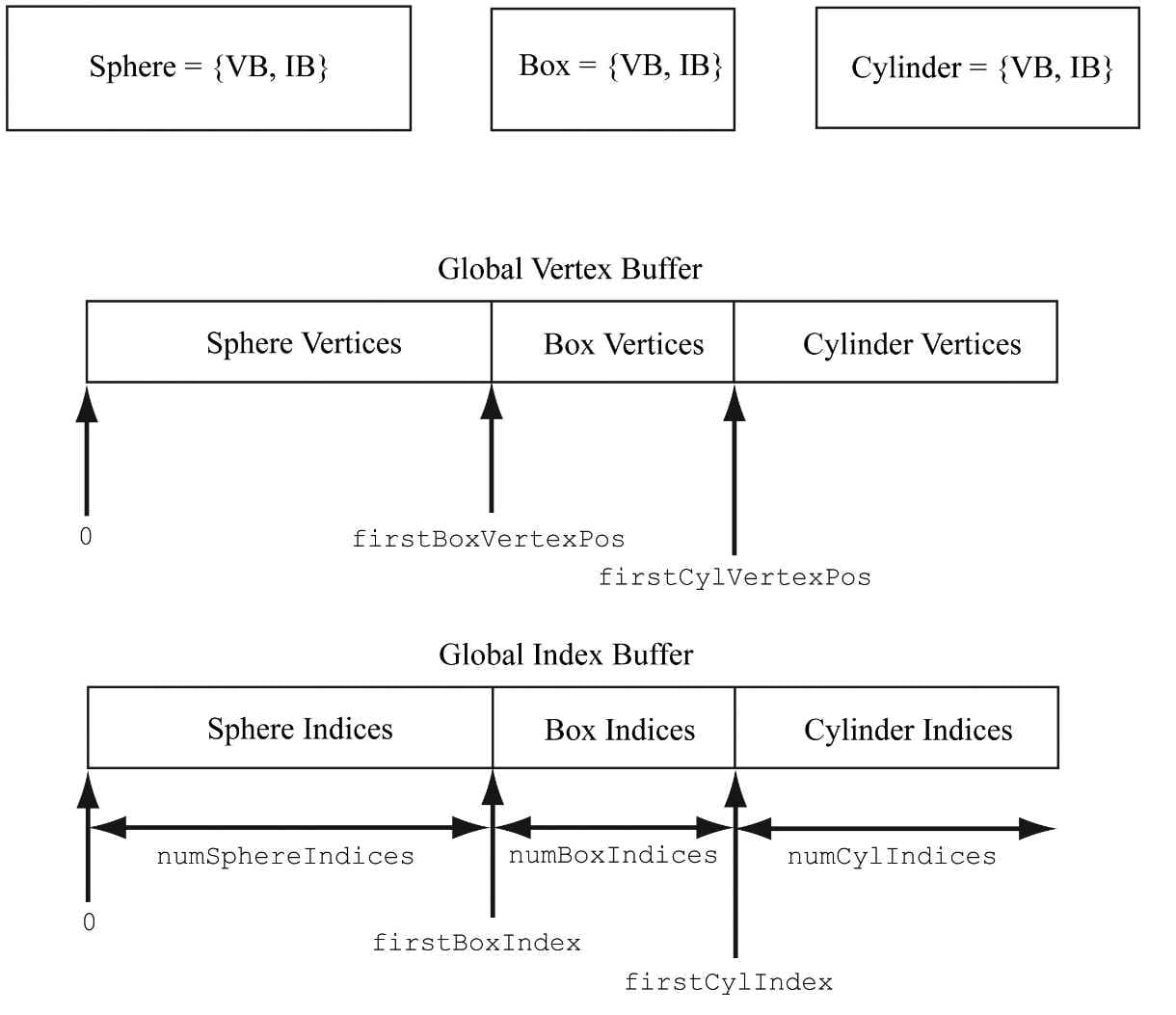
Figure 6.2. StartVertexLocation specifies the index (zero-based) of the first vertex in the vertex buffer to begin drawing. VertexCountPerInstance specifies the number of vertices to draw. Figure 6.2. StartVertexLocation specifies the index (zero-based) of the first vertex in the vertex buffer to begin drawing. VertexCountPerInstance specifies the number of vertices to draw. The DrawInstanced method does not specify what kind of primitive the vertices define. Should they be drawn as points, line lists, or triangle lists? Recall from §5.5.2 that the primitive topology state is set with the ID3D12GraphicsCommandList::IASetPrimitiveTopology method. Here is an example call: cmdList->IASetPrimitiveTopology(D3D_PRIMITIVE_TOPOLOGY_TRIANGLELIST); 6.3 INDICES AND INDEX BUFFERS Similar to vertices, in order for the GPU to access an array of indices, they need to be placed in a buffer GPU resource (ID3D12Resource). We call a buffer that stores indices an index buffer. Because our d3dUtil::CreateDefaultBuffer function works with generic data via a void*, we can use this same function to create an index buffer (or any default buffer). In order to bind an index buffer to the pipeline, we need to create an index buffer view to the index buffer resource. As with vertex buffer views, we do not need a descriptor heap for an index buffer view. An index buffer view is represented by the D3D12_INDEX_BUFFER_VIEW structure: typedef struct D3D12_INDEX_BUFFER_VIEW { D3D12_GPU_VIRTUAL_ADDRESS BufferLocation; UINT SizeInBytes; DXGI_FORMAT Format; } D3D12_INDEX_BUFFER_VIEW; 1. BufferLocation: The virtual address of the vertex buffer resource we want to create a view to. We can use the ID3D12Resource::GetGPUVirtualAddress method to get this. 2. SizeInBytes: The number of bytes to view in the index buffer starting from BufferLocation. 3. Format: The format of the indices which must be either DXGI_FORMAT_R16_UINT for 16-bit indices or DXGI_FORMAT_R32_UINT for 32-bit indices. You should use 16-bit indices to reduce memory and bandwidth, and only use 32-bit indices if you have index values that need the extra 32-bit range. As with vertex buffers, and other Direct3D resource for that matter, before we can use it, we need to bind it to the pipeline. An index buffer is bound to the input assembler stage with the ID3D12CommandList::SetIndexBuffer method. The following code shows how to create an index buffer defining the triangles of a cube, create a view to it, and bind it to the pipeline: std::uint16_t indices[] = { // front face 0, 1, 2, 0, 2, 3, // back face 4, 6, 5, 4, 7, 6, // left face 4, 5, 1, 4, 1, 0, // right face 3, 2, 6, 3, 6, 7, // top face 1, 5, 6, 1, 6, 2, // bottom face 4, 0, 3, 4, 3, 7 }; const UINT ibByteSize = 36 * sizeof(std::uint16_t); ComPtr<ID3D12Resource> IndexBufferGPU = nullptr; ComPtr<ID3D12Resource> IndexBufferUploader = nullptr; IndexBufferGPU = d3dUtil::CreateDefaultBuffer(md3dDevice.Get(), mCommandList.Get(), indices), ibByteSize, IndexBufferUploader); D3D12_INDEX_BUFFER_VIEW ibv; ibv.BufferLocation = IndexBufferGPU->GetGPUVirtualAddress(); ibv.Format = DXGI_FORMAT_R16_UINT; ibv.SizeInBytes = ibByteSize; mCommandList->IASetIndexBuffer(&ibv); Finally, when using indices, we must use the ID3D12GraphicsCommandList::DrawIndexedInstanced method instead of DrawInstanced: void ID3D12GraphicsCommandList::DrawIndexedInstanced( UINT IndexCountPerInstance, UINT InstanceCount, UINT StartIndexLocation, INT BaseVertexLocation, UINT StartInstanceLocation); 1. IndexCountPerInstance: The number of indices to draw (per instance). 2. InstanceCount: Used for an advanced technique called instancing; for now, set this to 1 as we only draw one instance. 3. StartIndexLocation: Index to an element in the index buffer that marks the starting point from which to begin reading indices. 4. BaseVertexLocation: An integer value to be added to the indices used in this draw call before the vertices are fetched. 5. StartInstanceLocation: Used for an advanced technique called instancing; for now, set this to 0. To illustrate these parameters, consider the following situation. Suppose we have three objects: a sphere, box, and cylinder. At first, each object has its own vertex buffer and its own index buffer. The indices in each local index buffer are relative to the corresponding local vertex buffer. Now suppose that we concatenate the vertices and indices of the sphere, box, and cylinder into one global vertex and index buffer, as shown in Figure 6.3. (One might concatenate vertex and index buffers because there is some API overhead when changing the vertex and index buffers. Most likely this will not be a bottleneck, but if you have many small vertex and index buffers that could be easily merged, it may be worth doing so for performance reasons.) After this concatenation, the indices are no longer correct, as they store index locations relative to their corresponding local vertex buffers, not the global one; thus the indices need to be recomputed to index correctly into the global vertex buffer. The original box indices were computed with the assumption that the box’s vertices ran through the indices
Figure 6.3. Concatenating several vertex buffers into one large vertex buffer, and concatenating several index buffers into one large index buffer. 0, 1, …, numBoxVertices-1 But after the merger, they run from firstBoxVertexPos, firstBoxVertexPos+1, …, firstBoxVertexPos+numBoxVertices-1 Therefore, to update the indices, we need to add firstBoxVertexPos to every box index. Likewise, we need to add firstCylVertexPos to every cylinder index. Note that the sphere’s indices do not need to be changed (since the first sphere vertex position is zero). Let us call the position of an object’s first vertex relative to the global vertex buffer its base vertex location. In general, the new indices of an object are computed by adding its base vertex location to each index. Instead of having to compute the new indices ourselves, we can let Direct3D do it by passing the base vertex location to the fourth parameter of DrawIndexedInstanced. We can then draw the sphere, box, and cylinder one-by-one with the following three calls: mCmdList->DrawIndexedInstanced( numSphereIndices, 1, 0, 0, 0); mCmdList->DrawIndexedInstanced( numBoxIndices, 1, firstBoxIndex, firstBoxVertexPos, 0); mCmdList->DrawIndexedInstanced( numCylIndices, 1, firstCylIndex, firstCylVertexPos, 0); The “Shapes” demo project in the next chapter uses this technique. 6.4 EXAMPLE VERTEX SHADER Below in an implementation of the simple vertex shader (recall §5.6): cbuffer cbPerObject : register(b0) { float4x4 gWorldViewProj; }; void VS(float3 iPosL : POSITION, float4 iColor : COLOR, out float4 oPosH : SV_POSITION, out float4 oColor : COLOR) { // Transform to homogeneous clip space. oPosH = mul(float4(iPosL, 1.0f), gWorldViewProj); // Just pass vertex color into the pixel shader. oColor = iColor; } Shaders are written in a language called the high level shading language (HLSL), which has similar syntax to C++, so it is easy to learn. Appendix B provides a concise reference to the HLSL. Our approach to teaching the HLSL and programming shaders will be example based. That is, as we progress through the book, we will introduce any new HLSL concepts we need in order to implement the demo at hand. Shaders are usually written in text-based files with a .hlsl extension. The vertex shader is the function called VS. Note that you can give the vertex shader any valid function name. This vertex shader has four parameters; the first two are input parameters, and the last two are output parameters (indicated by the out keyword). The HLSL does not have references or pointers, so to return multiple values from a function, you need to either use structures or out parameters. In HLSL, functions are always inlined. The first two input parameters form the input signature of the vertex shader and correspond to data members in our custom vertex structure we are using for the draw. The parameter semantics “:POSITION” and “:COLOR” are used for mapping the elements in the vertex structure to the vertex shader input parameters, as Figure 6.4 shows.
Figure 6.4. Each vertex element has an associated semantic specified by the D3D12_INPUT_ELEMENT_DESC array. Each parameter of the vertex shader also has an attached semantic. The semantics are used to match vertex elements with vertex shader parameters. The output parameters also have attached semantics (“:SV_POSITION” and “:COLOR”). These are used to map vertex shader outputs to the corresponding inputs of the next stage (either the geometry shader or pixel shader). Note that the SV_POSITION semantic is special (SV stands for system value). It is used to denote the vertex shader output element that holds the vertex position in homogeneous clip space. We must attach the SV_POSITION semantic to the position output because the GPU needs to be aware of this value because it is involved in operations the other attributes are not involved in, such as clipping, depth testing and rasterization. The semantic name for output parameters that are not system values can be any valid semantic name. The first line transforms the vertex position from local space to homogeneous clip space by multiplying by the 4 × 4 matrix gWorldViewProj: // Transform to homogeneous clip space. oPosH = mul(float4(iPosL, 1.0f), gWorldViewProj); The constructor syntax float4(iPosL, 1.0f) constructs a 4D vector and is equivalent to float4(iPosL.x, iPosL.y, iPosL.z, 1.0f); because we know the position of vertices are points and not vectors, we place a 1 in the fourth component (w = 1). The float2 and float3 types represent 2D and 3D vectors, respectively. The matrix variable gWorldViewProj lives in what is called a constant buffer, which will be discussed in the next section. The built-in function mul is used for the vector-matrix multiplication. Incidentally, the mul function is overloaded for matrix multiplications of different sizes; for example, you can use it to multiply two 4 × 4 matrices, two 3 × 3 matrices, or a 1 × 3 vector and a 3 × 3 matrix. The last line in the shader body just copies the input color to the output parameter so that the color will be fed into the next stage of the pipeline: oColor = iColor; We can equivalently rewrite the above vertex shader above using structures for the return type and input signature (as opposed to a long parameter list): cbuffer cbPerObject : register(b0) { float4x4 gWorldViewProj; }; struct VertexIn { float3 PosL : POSITION; float4 Color : COLOR; }; struct VertexOut { float4 PosH : SV_POSITION; float4 Color : COLOR; }; VertexOut VS(VertexIn vin) { VertexOut vout; // Transform to homogeneous clip space. vout.PosH = mul(float4(vin.PosL, 1.0f), gWorldViewProj); // Just pass vertex color into the pixel shader. vout.Color = vin.Color; return vout; }
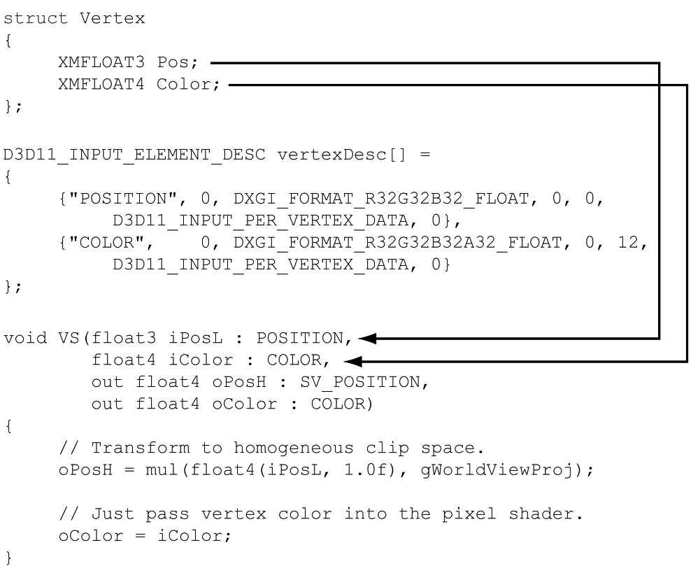
6.4.1 Input Layout Description and Input Signature Linking Note from Figure 6.4 that there is a linking between the attributes of the vertices being fed into the pipeline, which is defined by the input layout description. If you feed in vertices that do not supply all the inputs a vertex shader expects, an error will result. For example, the following vertex shader input signature and vertex data are incompatible: //-------------- // C++ app code //-------------- struct Vertex { XMFLOAT3 Pos; XMFLOAT4 Color; }; D3D12_INPUT_ELEMENT_DESC desc[] = { {"POSITION", 0, DXGI_FORMAT_R32G32B32_FLOAT, 0, 0, D3D12_INPUT_PER_VERTEX_DATA, 0}, {"COLOR", 0, DXGI_FORMAT_R32G32B32A32_FLOAT, 0, 12, D3D12_INPUT_PER_VERTEX_DATA, 0} }; //-------------- // Vertex shader //-------------- struct VertexIn { float3 PosL : POSITION; float4 Color : COLOR; float3 Normal : NORMAL; }; struct VertexOut { float4 PosH : SV_POSITION; float4 Color : COLOR; }; VertexOut VS(VertexIn vin) { … } As we will see in §6.9, when we create an ID3D12PipelineState object, we must specify both the input layout description and the vertex shader. Direct3D will then validate that the input layout description and vertex shader are compatible. The vertex data and input signature do not need to match exactly. What is needed is for the vertex data to provide all the data the vertex shader expects. Therefore, it is allowed for the vertex data to provide additional data the vertex shader does not use. That is, the following are compatible: //-------------- // C++ app code //-------------- struct Vertex { XMFLOAT3 Pos; XMFLOAT4 Color; XMFLOAT3 Normal; }; D3D12_INPUT_ELEMENT_DESC desc[] = { {"POSITION", 0, DXGI_FORMAT_R32G32B32_FLOAT, 0, 0, D3D12_INPUT_PER_VERTEX_DATA, 0}, {"COLOR", 0, DXGI_FORMAT_R32G32B32A32_FLOAT, 0, 12, D3D12_INPUT_PER_VERTEX_DATA, 0}, { "NORMAL", 0, DXGI_FORMAT_R32G32B32_FLOAT, 0, 28, D3D12_INPUT_PER_VERTEX_DATA, 0 } }; //-------------- // Vertex shader //-------------- struct VertexIn { float3 PosL : POSITION; float4 Color : COLOR; }; struct VertexOut { float4 PosH : SV_POSITION; float4 Color : COLOR; }; VertexOut VS(VertexIn vin) { … } Now consider the case where the vertex structure and input signature have matching vertex elements, but the types are different for the color attribute: //-------------- // C++ app code //-------------- struct Vertex { XMFLOAT3 Pos; XMFLOAT4 Color; }; D3D12_INPUT_ELEMENT_DESC desc[] = { {"POSITION", 0, DXGI_FORMAT_R32G32B32_FLOAT, 0, 0, D3D12_INPUT_PER_VERTEX_DATA, 0}, {"COLOR", 0, DXGI_FORMAT_R32G32B32A32_FLOAT, 0, 12, D3D12_INPUT_PER_VERTEX_DATA, 0} }; //-------------- // Vertex shader //-------------- struct VertexIn { float3 PosL : POSITION; int4 Color : COLOR; }; struct VertexOut { float4 PosH : SV_POSITION; float4 Color : COLOR; }; VertexOut VS(VertexIn vin) { … } This is actually legal because Direct3D allows the bits in the input registers to be reinterpreted. However, the VC++ debug output window gives the following warning: D3D12 WARNING: ID3D11Device::CreateInputLayout: The provided input signature expects to read an element with SemanticName/Index: ‘COLOR’/0 and component(s) of the type ‘int32’. However, the matching entry in the Input Layout declaration, element[1], specifies mismatched format: ‘R32G32B32A32_FLOAT’. This is not an error, since behavior is well defined: The element format determines what data conversion algorithm gets applied before it shows up in a shader register. Independently, the shader input signature defines how the shader will interpret the data that has been placed in its input registers, with no change in the bits stored. It is valid for the application to reinterpret data as a different type once it is in the vertex shader, so this warning is issued just in case reinterpretation was not intended by the author. 6.5 EXAMPLE PIXEL SHADER As discussed in §5.10.3, during rasterization vertex attributes output from the vertex shader (or geometry shader) are interpolated across the pixels of a triangle. The interpolated values are then fed into the pixel shader as input (§5.11). Assuming there is no geometry shader, Figure 6.5 illustrates the path vertex data takes up to now.
Figure 6.5. Each vertex element has an associated semantic specified by the D3D12_INPUT_ELEMENT_DESC array. Each parameter of the vertex shader also has an attached semantic. The semantics are used to match vertex elements with vertex shader parameters. Likewise, each output from the vertex shader has an attached semantic, and each pixel shader input parameter has an attached semantics. These semantics are used to map vertex shader outputs into the pixel shader input parameters. A pixel shader is like a vertex shader in that it is a function executed for each pixel fragment. Given the pixel shader input, the job of the pixel shader is to calculate a color value for the pixel fragment. We note that the pixel fragment may not survive and make it onto the back buffer; for example, it might be clipped in the pixel shader (the HLSL includes a clip function which can discard a pixel fragment from further processing), occluded by another pixel fragment with a smaller depth value, or the pixel fragment may be discarded by a later pipeline test like the stencil buffer test. Therefore, a pixel on the back buffer may have several pixel fragment candidates; this is the distinction between what is meant by “pixel fragment” and “pixel,” although sometimes the terms are used interchangeably, but context usually makes it clear what is meant.
Below is a simple pixel shader which corresponds to the vertex shader given in §6.4. For completeness, the vertex shader is shown again. cbuffer cbPerObject : register(b0) { float4x4 gWorldViewProj; }; void VS(float3 iPos : POSITION, float4 iColor : COLOR, out float4 oPosH : SV_POSITION, out float4 oColor : COLOR) { // Transform to homogeneous clip space. oPosH = mul(float4(iPos, 1.0f), gWorldViewProj); // Just pass vertex color into the pixel shader. oColor = iColor; } float4 PS(float4 posH : SV_POSITION, float4 color : COLOR) : SV_Target { return pin.Color; } In this example, the pixel shader simply returns the interpolated color value. Notice that the pixel shader input exactly matches the vertex shader output; this is a requirement. The pixel shader returns a 4D color value, and the SV_TARGET semantic following the function parameter listing indicates the return value type should match the render target format. We can equivalently rewrite the above vertex and pixel shaders using input/output structures. The notation varies in that we attach the semantics to the members of the input/output structures, and that we use a return statement for output instead of output parameters. cbuffer cbPerObject : register(b0) { float4x4 gWorldViewProj; }; struct VertexIn { float3 Pos : POSITION; float4 Color : COLOR; }; struct VertexOut { float4 PosH : SV_POSITION; float4 Color : COLOR; }; VertexOut VS(VertexIn vin) { VertexOut vout; // Transform to homogeneous clip space. vout.PosH = mul(float4(vin.Pos, 1.0f), gWorldViewProj); // Just pass vertex color into the pixel shader. vout.Color = vin.Color; return vout; } float4 PS(VertexOut pin) : SV_Target { return pin.Color; } 6.6 CONSTANT BUFFERS 6.6.1 Creating Constant Buffers A constant buffer is an example of a GPU resource (ID3D12Resource) whose data contents can be referenced in shader programs. As we will learn throughout this book, textures and other types of buffer resources can also be referenced in shader programs. The example vertex shader in the §6.4 had the code: cbuffer cbPerObject : register(b0) { float4x4 gWorldViewProj; }; This code refers to a cbuffer object (constant buffer) called cbPerObject. In this example, the constant buffer stores a single 4 × 4 matrix called gWorldViewProj, representing the combined world, view, and projection matrices used to transform a point from local space to homogeneous clip space. In HLSL, a 4 × 4 matrix is declared by the built-in float4x4 type; to declare a 3 × 4 matrix and 2 × 4 matrix, for example, you would use the float3x4 and float2x2 types, respectively. Unlike vertex and index buffers, constant buffers are usually updated once per frame by the CPU. For example, if the camera is moving every frame, the constant buffer would need to be updated with the new view matrix every frame. Therefore, we create constant buffers in an upload heap rather than a default heap so that we can update the contents from the CPU. Constant buffers also have the special hardware requirement that their size must be a multiple of the minimum hardware allocation size (256 bytes). Often we will need multiple constant buffers of the same type. For example, the above constant buffer cbPerObject stores constants that vary per object, so if we have n objects, then we will need n constant buffers of this type. The following code shows how we create a buffer that stores NumElements many constant buffers: struct ObjectConstants { DirectX::XMFLOAT4X4 WorldViewProj = MathHelper::Identity4x4(); }; UINT elementByteSize = d3dUtil::CalcConstantBufferByteSize(sizeof(ObjectConstants)); ComPtr<ID3D12Resource> mUploadCBuffer; device->CreateCommittedResource( &CD3DX12_HEAP_PROPERTIES(D3D12_HEAP_TYPE_UPLOAD), D3D12_HEAP_FLAG_NONE, &CD3DX12_RESOURCE_DESC::Buffer(mElementByteSize * NumElements), D3D12_RESOURCE_STATE_GENERIC_READ, nullptr, IID_PPV_ARGS(&mUploadCBuffer)); We can think of the mUploadCBuffer as storing an array of constant buffers of type ObjectConstants (with padding to make a multiple of 256 bytes). When it comes time to draw an object, we just bind a constant buffer view (CBV) to a subregion of the buffer that stores the constants for that object. Note that we will often call the buffer mUploadCBuffer a constant buffer since it stores an array of constant buffers. The utility function d3dUtil::CalcConstantBufferByteSize does the arithmetic to round the byte size of the buffer to be a multiple of the minimum hardware allocation size (256 bytes): UINT d3dUtil::CalcConstantBufferByteSize(UINT byteSize) { // Constant buffers must be a multiple of the minimum hardware // allocation size (usually 256 bytes). So round up to nearest // multiple of 256. We do this by adding 255 and then masking off // the lower 2 bytes which store all bits < 256. // Example: Suppose byteSize = 300. // (300 + 255) & ˜255 // 555 & ˜255 // 0x022B & ˜0x00ff // 0x022B & 0xff00 // 0x0200 // 512 return (byteSize + 255) & ˜255; }
// Implicitly padded to 256 bytes. cbuffer cbPerObject : register(b0) { float4x4 gWorldViewProj; }; // Explicitly padded to 256 bytes. cbuffer cbPerObject : register(b0) { float4x4 gWorldViewProj; float4x4 Pad0; float4x4 Pad1; float4x4 Pad1; };
Direct3D 12 introduced shader model 5.1. Shader model 5.1 has introduced an alternative HLSL syntax for defining a constant buffer which looks like this: struct ObjectConstants { float4x4 gWorldViewProj; uint matIndex; }; ConstantBuffer<ObjectConstants> gObjConstants : register(b0); Here the data elements of the constant buffer are just defined in a separate structure, and then a constant buffer is created from that structure. Fields of the constant buffer are then accessed in the shader using data member syntax: uint index = gObjConstants.matIndex; 6.6.2 Updating Constant Buffers Because a constant buffer is created with the heap type D3D12_HEAP_TYPE_UPLOAD, we can upload data from the CPU to the constant buffer resource. To do this, we first must obtain a pointer to the resource data, which can be done with the Map method: ComPtr<ID3D12Resource> mUploadBuffer; BYTE* mMappedData = nullptr; mUploadBuffer->Map(0, nullptr, reinterpret_cast<void**>(&mMappedData)); The first parameter is a subresource index identifying the subresource to map. For a buffer, the only subresource is the buffer itself, so we just set this to 0. The second parameter is an optional pointer to a D3D12_RANGE structure that describes the range of memory to map; specifying null maps the entire resource. The second parameter returns a pointer to the mapped data. To copy data from system memory to the constant buffer, we can just do a memcpy: memcpy(mMappedData, &data, dataSizeInBytes); When we are done with a constant buffer, we should Unmap it before releasing the memory: if(mUploadBuffer != nullptr) mUploadBuffer->Unmap(0, nullptr); mMappedData = nullptr; The first parameter to Unmap is a subresource index identifying the subresource to map, which will be 0 for a buffer. The second parameter to Unmap is an optional pointer to a D3D12_RANGE structure that describes the range of memory to unmap; specifying null unmaps the entire resource. 6.6.3 Upload Buffer Helper It is convenient to build a light wrapper around an upload buffer. We define the following class in UploadBuffer.h to make working with upload buffers easier. It handles the construction and destruction of an upload buffer resource for us, handles mapping and unmapping the resource, and provides the CopyData method to update a particular element in the buffer. We use the CopyData method when we need to change the contents of an upload buffer from the CPU (e.g., when the view matrix changes). Note that this class can be used for any upload buffer, not necessarily a constant buffer. If we do use it for a constant buffer, however, we need to indicate so via the isConstantBuffer constructor parameter. If it is storing a constant buffer, then it will automatically pad the memory to make each constant buffer a multiple of 256 bytes. template<typename T> class UploadBuffer { public: UploadBuffer(ID3D12Device* device, UINT elementCount, bool isConstantBuffer) : mIsConstantBuffer(isConstantBuffer) { mElementByteSize = sizeof(T); // Constant buffer elements need to be multiples of 256 bytes. // This is because the hardware can only view constant data // at m*256 byte offsets and of n*256 byte lengths. // typedef struct D3D12_CONSTANT_BUFFER_VIEW_DESC { // UINT64 OffsetInBytes; // multiple of 256 // UINT SizeInBytes; // multiple of 256 // } D3D12_CONSTANT_BUFFER_VIEW_DESC; if(isConstantBuffer) mElementByteSize = d3dUtil::CalcConstantBufferByteSize(sizeof(T)); ThrowIfFailed(device->CreateCommittedResource( &CD3DX12_HEAP_PROPERTIES(D3D12_HEAP_TYPE_UPLOAD), D3D12_HEAP_FLAG_NONE, &CD3DX12_RESOURCE_DESC::Buffer(mElementByteSize*elementCount), D3D12_RESOURCE_STATE_GENERIC_READ, nullptr, IID_PPV_ARGS(&mUploadBuffer))); ThrowIfFailed(mUploadBuffer->Map(0, nullptr, reinterpret_cast<void**>(&mMappedData))); // We do not need to unmap until we are done with the resource. // However, we must not write to the resource while it is in use by // the GPU (so we must use synchronization techniques). } UploadBuffer(const UploadBuffer& rhs) = delete; UploadBuffer& operator=(const UploadBuffer& rhs) = delete; ˜UploadBuffer() { if(mUploadBuffer != nullptr) mUploadBuffer->Unmap(0, nullptr); mMappedData = nullptr; } ID3D12Resource* Resource()const { return mUploadBuffer.Get(); } void CopyData(int elementIndex, const T& data) { memcpy(&mMappedData[elementIndex*mElementByteSize], &data, sizeof(T)); } private: Microsoft::WRL::ComPtr<ID3D12Resource> mUploadBuffer; BYTE* mMappedData = nullptr; UINT mElementByteSize = 0; bool mIsConstantBuffer = false; }; Typically, the world matrix of an object will change when it moves/rotates/scales, the view matrix changes when the camera moves/rotates, and the projection matrix changes when the window is resized. In our demo for this chapter, we allow the user to rotate and move the camera with the mouse, and we update the combined world-view-projection matrix with the new view matrix every frame in the Update function: void BoxApp::OnMouseMove(WPARAM btnState, int x, int y) { if((btnState & MK_LBUTTON) != 0) { // Make each pixel correspond to a quarter of a degree. float dx = XMConvertToRadians(0.25f*static_cast<float> (x - mLastMousePos.x)); float dy = XMConvertToRadians(0.25f*static_cast<float> (y - mLastMousePos.y)); // Update angles based on input to orbit camera around box. mTheta += dx; mPhi += dy; // Restrict the angle mPhi. mPhi = MathHelper::Clamp(mPhi, 0.1f, MathHelper::Pi - 0.1f); } else if((btnState & MK_RBUTTON) != 0) { // Make each pixel correspond to 0.005 unit in the scene. float dx = 0.005f*static_cast<float>(x - mLastMousePos.x); float dy = 0.005f*static_cast<float>(y - mLastMousePos.y); // Update the camera radius based on input. mRadius += dx - dy; // Restrict the radius. mRadius = MathHelper::Clamp(mRadius, 3.0f, 15.0f); } mLastMousePos.x = x; mLastMousePos.y = y; } void BoxApp::Update(const GameTimer& gt) { // Convert Spherical to Cartesian coordinates. float x = mRadius*sinf(mPhi)*cosf(mTheta); float z = mRadius*sinf(mPhi)*sinf(mTheta); float y = mRadius*cosf(mPhi); // Build the view matrix. XMVECTOR pos = XMVectorSet(x, y, z, 1.0f); XMVECTOR target = XMVectorZero(); XMVECTOR up = XMVectorSet(0.0f, 1.0f, 0.0f, 0.0f); XMMATRIX view = XMMatrixLookAtLH(pos, target, up); XMStoreFloat4x4(&mView, view); XMMATRIX world = XMLoadFloat4x4(&mWorld); XMMATRIX proj = XMLoadFloat4x4(&mProj); XMMATRIX worldViewProj = world*view*proj; // Update the constant buffer with the latest worldViewProj matrix. ObjectConstants objConstants; XMStoreFloat4x4(&objConstants.WorldViewProj, XMMatrixTranspose(worldViewProj)); mObjectCB->CopyData(0, objConstants); } 6.6.4 Constant Buffer Descriptors Recall from §4.1.6 that we bind a resource to the rendering pipeline through a descriptor object. So far we have used descriptors/views for render targets, depth/stencil buffers, and vertex and index buffers. We also need descriptors to bind constant buffers to the pipeline. Constant buffer descriptors live in a descriptor heap of type D3D12_DESCRIPTOR_HEAP_TYPE_CBV_SRV_UAV. Such a heap can store a mixture of constant buffer, shader resource, and unordered access descriptors. To store these new types of descriptors we will need to create a new descriptor heap of this type: D3D12_DESCRIPTOR_HEAP_DESC cbvHeapDesc; cbvHeapDesc.NumDescriptors = 1; cbvHeapDesc.Type = D3D12_DESCRIPTOR_HEAP_TYPE_CBV_SRV_UAV; cbvHeapDesc.Flags = D3D12_DESCRIPTOR_HEAP_FLAG_SHADER_VISIBLE; cbvHeapDesc.NodeMask = 0; ComPtr<ID3D12DescriptorHeap> mCbvHeap md3dDevice->CreateDescriptorHeap(&cbvHeapDesc, IID_PPV_ARGS(&mCbvHeap)); This code is similar to how we created the render target and depth/stencil buffer descriptor heaps. However, one important difference is that we specify the D3D12_DESCRIPTOR_HEAP_FLAG_SHADER_VISIBLE flag to indicate that these descriptors will be accessed by shader programs. In the demo for his chapter, we have no SRV or UAV descriptors, and we are only going to draw one object; therefore, we only need 1 descriptor in this heap to store 1 CBV. A constant buffer view is created by filling out a D3D12_CONSTANT_BUFFER_VIEW_DESC instance and calling ID3D12Device::CreateConstantBufferView: // Constant data per-object. struct ObjectConstants { XMFLOAT4X4 WorldViewProj = MathHelper::Identity4x4(); }; // Constant buffer to store the constants of n object. std::unique_ptr<UploadBuffer<ObjectConstants>> mObjectCB = nullptr; mObjectCB = std::make_unique<UploadBuffer<ObjectConstants>>( md3dDevice.Get(), n, true); UINT objCBByteSize = d3dUtil::CalcConstantBufferByteSize(sizeof(ObjectConstants)); // Address to start of the buffer (0th constant buffer). D3D12_GPU_VIRTUAL_ADDRESS cbAddress = mObjectCB->Resource()->GetGPUVirtualAddress(); // Offset to the ith object constant buffer in the buffer. int boxCBufIndex = i; cbAddress += boxCBufIndex*objCBByteSize; D3D12_CONSTANT_BUFFER_VIEW_DESC cbvDesc; cbvDesc.BufferLocation = cbAddress; cbvDesc.SizeInBytes = d3dUtil::CalcConstantBufferByteSize(sizeof(ObjectConstants)); md3dDevice->CreateConstantBufferView( &cbvDesc, mCbvHeap->GetCPUDescriptorHandleForHeapStart()); The D3D12_CONSTANT_BUFFER_VIEW_DESC structure describes a subset of the constant buffer resource to bind to the HLSL constant buffer structure. As mentioned, typically a constant buffer stores an array of per-object constants for n objects, but we can get a view to the ith object constant data by using the BufferLocation and SizeInBytes. The D3D12_CONSTANT_BUFFER_VIEW_DESC::SizeInBytes and D3D12_CONSTANT_BUFFER_VIEW_DESC::OffsetInBytes members must by a multiple of 256 bytes due to hardware requirements. For example, if you specified 64, then you would get the following debug errors: D3D12 ERROR: ID3D12Device::CreateConstantBufferView: SizeInBytes of 64 is invalid. Device requires SizeInBytes be a multiple of 256. D3D12 ERROR: ID3D12Device:: CreateConstantBufferView: OffsetInBytes of 64 is invalid. Device requires OffsetInBytes be a multiple of 256. 6.6.5 Root Signature and Descriptor Tables Generally, different shader programs will expect different resources to be bound to the rendering pipeline before a draw call is executed. Resources are bound to particular register slots, where they can be accessed by shader programs. For example, the previous vertex and pixel shader expected only a constant buffer to be bound to register b0. A more advanced set of vertex and pixel shaders that we use later in this book expect several constant buffers, textures, and samplers to be bound to various register slots: // Texture resource bound to texture register slot 0. Texture2D gDiffuseMap : register(t0); // Sampler resources bound to sampler register slots 0-5. SamplerState gsamPointWrap : register(s0); SamplerState gsamPointClamp : register(s1); SamplerState gsamLinearWrap : register(s2); SamplerState gsamLinearClamp : register(s3); SamplerState gsamAnisotropicWrap : register(s4); SamplerState gsamAnisotropicClamp : register(s5); // cbuffer resource bound to cbuffer register slots 0-2 cbuffer cbPerObject : register(b0) { float4x4 gWorld; float4x4 gTexTransform; }; // Constant data that varies per material. cbuffer cbPass : register(b1) { float4x4 gView; float4x4 gProj; […] // Other fields omitted for brevity. }; cbuffer cbMaterial : register(b2) { float4 gDiffuseAlbedo; float3 gFresnelR0; float gRoughness; float4x4 gMatTransform; }; The root signature defines what resources the application will bind to the rendering pipeline before a draw call can be executed and where those resources get mapped to shader input registers. The root signature must be compatible with the shaders it will be used with (i.e., the root signature must provide all the resources the shaders expect to be bound to the rendering pipeline before a draw call can be executed); this will be validated when the pipeline state object is created (§6.9). Different draw calls may use a different set of shader programs, which will require a different root signature.
A root signature is represented in Direct3D by the ID3D12RootSignature interface. It is defined by an array of root parameters that describe the resources the shaders expect for a draw call. A root parameter can be a root constant, root descriptor, or descriptor table. We will discuss root constants and root descriptors in the next chapter; in this chapter, we will just use descriptor tables. A descriptor table specifies a contiguous range of descriptors in a descriptor heap. The following code below creates a root signature that has one root parameter that is a descriptor table large enough to store one CBV (constant buffer view): // Root parameter can be a table, root descriptor or root constants. CD3DX12_ROOT_PARAMETER slotRootParameter[1]; // Create a single descriptor table of CBVs. CD3DX12_DESCRIPTOR_RANGE cbvTable; cbvTable.Init( D3D12_DESCRIPTOR_RANGE_TYPE_CBV, 1, // Number of descriptors in table 0);// base shader register arguments are bound to for this root parameter slotRootParameter[0].InitAsDescriptorTable( 1, // Number of ranges &cbvTable); // Pointer to array of ranges // A root signature is an array of root parameters. CD3DX12_ROOT_SIGNATURE_DESC rootSigDesc(1, slotRootParameter, 0, nullptr, D3D12_ROOT_SIGNATURE_FLAG_ALLOW_INPUT_ASSEMBLER_INPUT_LAYOUT); // create a root signature with a single slot which points to a // descriptor range consisting of a single constant buffer. ComPtr<ID3DBlob> serializedRootSig = nullptr; ComPtr<ID3DBlob> errorBlob = nullptr; HRESULT hr = D3D12SerializeRootSignature(&rootSigDesc, D3D_ROOT_SIGNATURE_VERSION_1, serializedRootSig.GetAddressOf(), errorBlob.GetAddressOf()); ThrowIfFailed(md3dDevice->CreateRootSignature( 0, serializedRootSig->GetBufferPointer(), serializedRootSig->GetBufferSize(), IID_PPV_ARGS(&mRootSignature))); We will describe CD3DX12_ROOT_PARAMETER and CD3DX12_DESCRIPTOR_RANGE more in the next chapter, but for now just understand that the code CD3DX12_ROOT_PARAMETER slotRootParameter[1]; CD3DX12_DESCRIPTOR_RANGE cbvTable; cbvTable.Init( D3D12_DESCRIPTOR_RANGE_TYPE_CBV, // table type 1, // Number of descriptors in table 0);// base shader register arguments are bound to for this root parameter slotRootParameter[0].InitAsDescriptorTable( 1, // Number of ranges &cbvTable); // Pointer to array of ranges creates a root parameter that expects a descriptor table of 1 CBV that gets bound to constant buffer register 0 (i.e., register(b0) in the HLSL code).
The root signature only defines what resources the application will bind to the rendering pipeline; it does not actually do any resource binding. Once a root signature has been set with a command list, we use the ID3D12GraphicsCommandList::SetGraphicsRootDescriptorTable to bind a descriptor table to the pipeline: void ID3D12GraphicsCommandList::SetGraphicsRootDescriptorTable( UINT RootParameterIndex, D3D12_GPU_DESCRIPTOR_HANDLE BaseDescriptor); 1. RootParameterIndex: Index of the root parameter we are setting. 2. BaseDescriptor: Handle to a descriptor in the heap that specifies the first descriptor in the table being set. For example, if the root signature specified that this table had five descriptors, then BaseDescriptor and the next four descriptors in the heap are being set to this root table. The following code sets the root signature and CBV heap to the command list, and sets the descriptor table identifying the resource we want to bind to the pipeline: mCommandList->SetGraphicsRootSignature(mRootSignature.Get()); ID3D12DescriptorHeap* descriptorHeaps[] = { mCbvHeap.Get() }; mCommandList->SetDescriptorHeaps(_countof(descriptorHeaps), descriptorHeaps); // Offset the CBV we want to use for this draw call. CD3DX12_GPU_DESCRIPTOR_HANDLE cbv(mCbvHeap ->GetGPUDescriptorHandleForHeapStart()); cbv.Offset(cbvIndex, mCbvSrvUavDescriptorSize); mCommandList->SetGraphicsRootDescriptorTable(0, cbv);
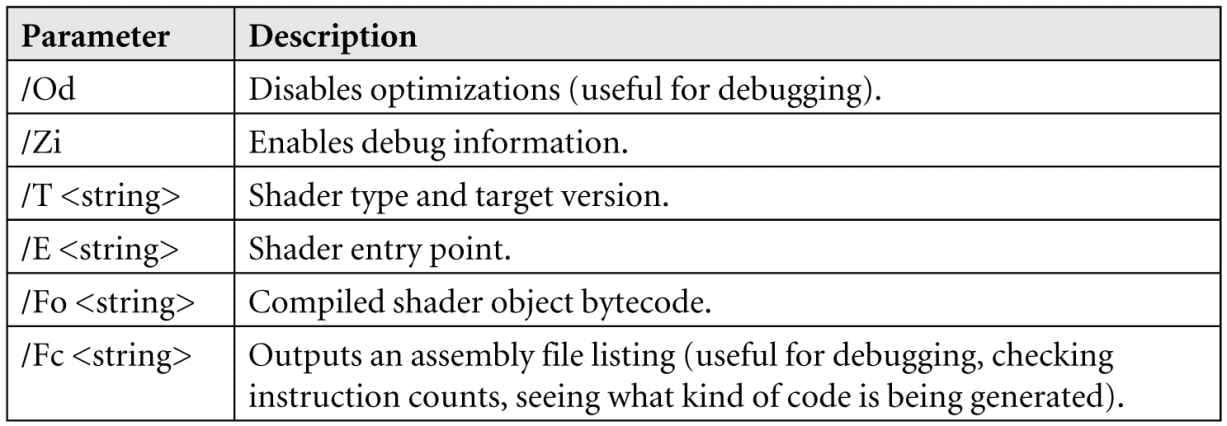
6.7 COMPILING SHADERS In Direct3D, shader programs must first be compiled to a portable bytecode. The graphics driver will then take this bytecode and compile it again into optimal native instructions for the system’s GPU [ATI1]. At runtime, we can compile a shader with the following function: HRESULT D3DCompileFromFile( LPCWSTR pFileName, const D3D_SHADER_MACRO *pDefines, ID3DInclude *pInclude, LPCSTR pEntrypoint, LPCSTR pTarget, UINT Flags1, UINT Flags2, ID3DBlob **ppCode, ID3DBlob **ppErrorMsgs); 1. pFileName: The name of the .hlsl file that contains the HLSL source code we want to compile. 2. pDefines: Advanced option we do not use; see the SDK documentation. We always specify null in this book. 3. pInclude: Advanced option we do not use; see the SDK documentation. We always specify null in this book. 4. pEntrypoint: The function name of the shader’s entry point. A .hlsl can contain multiple shaders programs (e.g., one vertex shader and one pixel shader), so we need to specify the entry point of the particular shader we want to compile. 5. pTarget: A string specifying the shader program type and version we are using. In this book, we target versions 5.0 and 5.1. a) vs_5_0 and vs_5_1: Vertex shader 5.0 and 5.1, respectively. b) hs_5_0 and hs_5_1: Hull shader 5.0 and 5.1, respectively. c) ds_5_0 and ds_5_1: Domain shader 5.0 and 5.1, respectively. d) gs_5_0 and gs_5_1: Geometry shader 5.0 and 5.1, respectively. e) ps_5_0 and ps_5_1: Pixel shader 5.0 and 5.1, respectively. f) cs_5_0 and cs_5_1: Compute shader 5.0 and 5.1, respectively. 6. Flags1: Flags to specify how the shader code should be compiled. There are quite a few of these flags listed in the SDK documentation, but the only two we use in this book are: a) D3DCOMPILE_DEBUG: Compiles the shaders in debug mode. b) D3DCOMPILE_SKIP_OPTIMIZATION: Instructs the compiler to skip optimizations (useful for debugging). 7. Flags2: Advanced effect compilation options we do not use; see the SDK documentation. 8. ppCode: Returns a pointer to a ID3DBlob data structure that stores the compiled shader object bytecode. 9. ppErrorMsgs: Returns a pointer to a ID3DBlob data structure that stores a string containing the compilation errors, if any. The type ID3DBlob is just a generic chunk of memory that has two methods: 1. LPVOID GetBufferPointer: Returns a void* to the data, so it must be casted to the appropriate type before use (see the example below). 2. SIZE_T GetBufferSize: Returns the byte size of the buffer. To support error output, we implement the following helper function to compile shaders at runtime in d3dUtil.h/.cpp: ComPtr<ID3DBlob> d3dUtil::CompileShader( const std::wstring& filename, const D3D_SHADER_MACRO* defines, const std::string& entrypoint, const std::string& target) { // Use debug flags in debug mode. UINT compileFlags = 0; #if defined(DEBUG) || defined(_DEBUG) compileFlags = D3DCOMPILE_DEBUG | D3DCOMPILE_SKIP_OPTIMIZATION; #endif HRESULT hr = S_OK; ComPtr<ID3DBlob> byteCode = nullptr; ComPtr<ID3DBlob> errors; hr = D3DCompileFromFile(filename.c_str(), defines, D3D_COMPILE_STANDARD_FILE_INCLUDE, entrypoint.c_str(), target.c_str(), compileFlags, 0, &byteCode, &errors); // Output errors to debug window. if(errors != nullptr) OutputDebugStringA((char*)errors->GetBufferPointer()); ThrowIfFailed(hr); return byteCode; } Here is an example of calling this function: ComPtr<ID3DBlob> mvsByteCode = nullptr; ComPtr<ID3DBlob> mpsByteCode = nullptr; mvsByteCode = d3dUtil::CompileShader(L"Shaders\\color.hlsl", nullptr, "VS", "vs_5_0"); mpsByteCode = d3dUtil::CompileShader(L"Shaders\\color.hlsl", nullptr, "PS", "ps_5_0"); HLSL errors and warnings will be returned through the ppErrorMsgs parameter. For example, if we misspelled the mul function, then we get the following error output to the debug window: Shaders\color.hlsl(29,14-55): error X3004: undeclared identifier ‘mu’ Compiling a shader does not bind it to the rendering pipeline for use. We will see how to do that in §6.9. 6.7.1 Offline Compilation Instead of compiling shaders at runtime, we can compile them offline in a separate step (e.g., a build step, or as part of an asset content pipeline process). There are a few reasons to do this: 1. For complicated shaders, compilation can take a long time. Therefore, compiling offline will make your loading times faster. 2. It is convenient to see shader compilation errors earlier in the build process rather than at runtime. 3. Windows 8 Store apps must use offline compilation. It is the common practice to use the .cso (compiled shader object) extension for compiled shaders. To compile shaders offline we use the FXC tool that comes with DirectX. This is a command line tool. To compile a vertex and pixel shader stored in color.hlsl with entry points VS and PS, respectively, with debugging we would write: fxc "color.hlsl" /Od /Zi /T vs_5_0 /E "VS" /Fo "color_vs.cso" /Fc "color_vs.asm" fxc "color.hlsl" /Od /Zi /T ps_5_0 /E "PS" /Fo "color_ps.cso" /Fc "color_ps.asm" To compile a vertex and pixel shader stored in color.hlsl with entry points VS and PS, respectively, for release we would write: fxc "color.hlsl" /T vs_5_0 /E "VS" /Fo "color_vs.cso" /Fc "color_vs.asm" fxc "color.hlsl" /T ps_5_0 /E "PS" /Fo "color_ps.cso" /Fc "color_ps.asm"
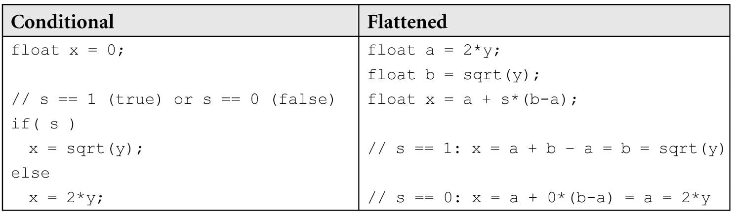
If you try to compile a shader with a syntax error, FXC will output the error/warning to the command window. For example, if we misname a variable in the color.hlsl effect file: // Should be gWorldViewProj, not worldViewProj! vout.PosH = mul(float4(vin.Pos, 1.0f), worldViewProj); Then we get quite a few errors from this one mistake (the top error being the key one to fix) listed in the debut output window: color.hlsl(29,42-54): error X3004: undeclared identifier ‘worldViewProj’ color.hlsl(29,14-55): error X3013: ‘mul’: no matching 2 parameter intrinsic function color.hlsl(29,14-55): error X3013: Possible intrinsic functions are: color.hlsl(29,14-55): error X3013: mul(float|half… Getting the error messages at compile time is much more convenient than runtime. We have shown how to compile our vertex and pixel shaders offline to .cso files. Therefore, we no longer need to do it at runtime (i.e., we do not need to call D3DCompileFromFile). However, we still need to load the compiled shader object bytecode from the .cso files into our app. This can be done using standard C++ file input mechanisms like so: ComPtr<ID3DBlob> d3dUtil::LoadBinary(const std::wstring& filename) { std::ifstream fin(filename, std::ios::binary); fin.seekg(0, std::ios_base::end); std::ifstream::pos_type size = (int)fin.tellg(); fin.seekg(0, std::ios_base::beg); ComPtr<ID3DBlob> blob; ThrowIfFailed(D3DCreateBlob(size, blob.GetAddressOf())); fin.read((char*)blob->GetBufferPointer(), size); fin.close(); return blob; } … ComPtr<ID3DBlob> mvsByteCode = d3dUtil::LoadBinary(L"Shaders\\color_vs.cso"); ComPtr<ID3DBlob> mpsByteCode = d3dUtil::LoadBinary(L"Shaders\\color_ps.cso"); 6.7.2 Generated Assembly The /Fc optional parameter to FXC generates the generated portable assembly code. Looking at the assembly of your shaders from time to time is useful to check shader instruction counts, and to see what kind of code is being generated—sometimes it might be different than what you expect. For example, if you have a conditional statement in your HLSL code, then you might expect there to be a branching instruction in the assembly code. In the early days of programmable GPUs, branching in shaders used to be expensive, and so sometimes the compiler will flatten a conditional statement by evaluating both branches and then interpolate between the two to pick the right answer. That is, the following codes will give the same answer:
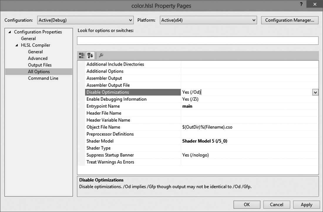
So the flattened method gives us the same result without any branching, but without looking at the assembly code, we would not know if flattening was happening, or if a true branch instruction was generated. The point being that sometimes you want to look at the assembly to see what is really going on. The following is an example of the assembly generated for the vertex shader in color.hlsl: // // Generated by Microsoft (R) HLSL Shader Compiler 6.4.9844.0 // // // Buffer Definitions: // // cbuffer cbPerObject // { // // float4x4 gWorldViewProj; // Offset: 0 Size: 64 // // } // // // Resource Bindings: // // Name Type Format Dim Slot Elements // ------------------------------ ---------- ------- ----------- ---- --------- // cbPerObject cbuffer NA NA 0 1 // // // // Input signature: // // Name Index Mask Register SysValue Format Used // -------------------- ----- ------ -------- -------- ------- ------ // POSITION 0 xyz 0 NONE float xyz // COLOR 0 xyzw 1 NONE float xyzw // // // Output signature: // // Name Index Mask Register SysValue Format Used // -------------------- ----- ------ -------- -------- ------- ------ // SV_POSITION 0 xyzw 0 POS float xyzw // COLOR 0 xyzw 1 NONE float xyzw // vs_5_0 dcl_globalFlags refactoringAllowed | skipOptimization dcl_constantbuffer cb0[4], immediateIndexed dcl_input v0.xyz dcl_input v1.xyzw dcl_output_siv o0.xyzw, position dcl_output o1.xyzw dcl_temps 2 // // Initial variable locations: // v0.x <- vin.PosL.x; v0.y <- vin.PosL.y; v0.z <- vin.PosL.z; // v1.x <- vin.Color.x; v1.y <- vin.Color.y; v1.z <- vin.Color.z; v1.w <- vin.Color.w; // o1.x <- <VS return value>.Color.x; // o1.y <- <VS return value>.Color.y; // o1.z <- <VS return value>.Color.z; // o1.w <- <VS return value>.Color.w; // o0.x <- <VS return value>.PosH.x; // o0.y <- <VS return value>.PosH.y; // o0.z <- <VS return value>.PosH.z; // o0.w <- <VS return value>.PosH.w // #line 29 "color.hlsl" mov r0.xyz, v0.xyzx mov r0.w, l(1.000000) dp4 r1.x, r0.xyzw, cb0[0].xyzw // r1.x <- vout.PosH.x dp4 r1.y, r0.xyzw, cb0[1].xyzw // r1.y <- vout.PosH.y dp4 r1.z, r0.xyzw, cb0[2].xyzw // r1.z <- vout.PosH.z dp4 r1.w, r0.xyzw, cb0[3].xyzw // r1.w <- vout.PosH.w #line 32 mov r0.xyzw, v1.xyzw // r0.x <- vout.Color.x; r0.y <- vout.Color.y; // r0.z <- vout.Color.z; r0.w <- vout.Color.w mov o0.xyzw, r1.xyzw mov o1.xyzw, r0.xyzw ret // Approximately 10 instruction slots used 6.7.3 Using Visual Studio to Compile Shaders Offline Visual Studio 2013 has some integrated support for compiling shader programs. You can add .hlsl files to your project, and Visual Studio (VS) will recognize them and provide compilation options (see Figure 6.6). These options provide a UI for the FXC parameters. When you add a HLSL file to your VS project, it will become part of the build process, and the shader will be compiled with FXC.
Figure 6.6. Adding a custom build tool to the project. One downside to using the VS integrated HLSL support is that it only supports one shader program per file. Therefore, you cannot store both a vertex and pixel shader in one file. Moreover, sometimes we want to compile the same shader program with different preprocessor directives to get different variations of a shader. Again, this will not be possible using the integrated VS support since it is one .cso output per .hlsl input. 6.8 RASTERIZER STATE While many parts of the rendering pipeline are programmable, some parts are only configurable. The rasterizer state group, represented by the D3D12_RASTERIZER_DESC structure, is used to configure the rasterization stage of the rendering pipeline: typedef struct D3D12_RASTERIZER_DESC { D3D12_FILL_MODE FillMode; // Default: D3D12_FILL_SOLID D3D12_CULL_MODE CullMode; // Default: D3D12_CULL_BACK BOOL FrontCounterClockwise; // Default: false INT DepthBias; // Default: 0 FLOAT DepthBiasClamp; // Default: 0.0f FLOAT SlopeScaledDepthBias; // Default: 0.0f BOOL DepthClipEnable; // Default: true BOOL ScissorEnable; // Default: false BOOL MultisampleEnable; // Default: false BOOL AntialiasedLineEnable; // Default: false UINT ForcedSampleCount; // Default: 0 // Default: D3D12_CONSERVATIVE_RASTERIZATION_MODE_OFF D3D12_CONSERVATIVE_RASTERIZATION_MODE ConservativeRaster; } D3D12_RASTERIZER_DESC; Most of these members are advanced or not used very often; therefore, we refer you to the SDK documentation for the descriptions of each member. We only describe four here. 1. FillMode: Specify D3D12_FILL_WIREFRAME for wireframe rendering or D3D12_FILL_SOLID for solid rendering. Solid rendering is the default. 2. CullMode: Specify D3D12_CULL_NONE to disable culling, D3D12_CULL_BACK to cull back-facing triangles, or D3D12_CULL_FRONT to cull front-facing triangles. Back-facing triangles are culled by default. 3. FrontCounterClockwise: Specify false if you want triangles ordered clockwise (with respect to the camera) to be treated as front-facing and triangles ordered counterclockwise (with respect to the camera) to be treated as back-facing. Specify true if you want triangles ordered counterclockwise (with respect to the camera) to be treated as front-facing and triangles ordered clockwise (with respect to the camera) to be treated as back-facing. This state is false by default. 4. ScissorEnable: Specify true to enable the scissor test (§4.3.10) and false to disable it. The default is false. The following code shows how to create a rasterize state that turns on wireframe mode and disables backface culling: CD3DX12_RASTERIZER_DESC rsDesc(D3D12_DEFAULT); rsDesc.FillMode = D3D12_FILL_WIREFRAME; rsDesc.CullMode = D3D12_CULL_NONE; CD3DX12_RASTERIZER_DESC is a convenience class that extends D3D12_RASTERIZER_DESC and adds some helper constructors. In particular, it has a constructor that takes an object of type CD3D12_DEFAULT, which is just a dummy type used for overloading to indicate the rasterizer state members should be initialized to the default values. CD3D12_DEFAULT and D3D12_DEFAULT are defined like so: struct CD3D12_DEFAULT {}; extern const DECLSPEC_SELECTANY CD3D12_DEFAULT D3D12_DEFAULT; D3D12_DEFAULT is used in several of the Direct3D convenience classes. 6.9 PIPELINE STATE OBJECT We have shown, for example, how to describe an input layout description, how to create vertex and pixel shaders, and how to configure the rasterizer state group. However, we have not yet shown how to bind any of these objects to the graphics pipeline for actual use. Most of the objects that control the state of the graphics pipeline are specified as an aggregate called a pipeline state object (PSO), which is represented by the ID3D12PipelineState interface. To create a PSO, we first describe it by filling out a D3D12_GRAPHICS_PIPELINE_STATE_DESC instance: typedef struct D3D12_GRAPHICS_PIPELINE_STATE_DESC { ID3D12RootSignature *pRootSignature; D3D12_SHADER_BYTECODE VS; D3D12_SHADER_BYTECODE PS; D3D12_SHADER_BYTECODE DS; D3D12_SHADER_BYTECODE HS; D3D12_SHADER_BYTECODE GS; D3D12_STREAM_OUTPUT_DESC StreamOutput; D3D12_BLEND_DESC BlendState; UINT SampleMask; D3D12_RASTERIZER_DESC RasterizerState; D3D12_DEPTH_STENCIL_DESC DepthStencilState; D3D12_INPUT_LAYOUT_DESC InputLayout; D3D12_PRIMITIVE_TOPOLOGY_TYPE PrimitiveTopologyType; UINT NumRenderTargets; DXGI_FORMAT RTVFormats[8]; DXGI_FORMAT DSVFormat; DXGI_SAMPLE_DESC SampleDesc; } D3D12_GRAPHICS_PIPELINE_STATE_DESC; 1. pRootSignature: Pointer to the root signature to be bound with this PSO. The root signature must be compatible with the shaders specified with this PSO. 2. VS: The vertex shader to bind. This is specified by the D3D12_SHADER_BYTECODE structure which is a pointer to the compiled bytecode data, and the size of the bytecode data in bytes. typedef struct D3D12_SHADER_BYTECODE { const BYTE *pShaderBytecode; SIZE_T BytecodeLength; } D3D12_SHADER_BYTECODE; 3. PS: The pixel shader to bind. 4. DS: The domain shader to bind (we will discuss this type of shader in a later chapter). 5. HS: The hull shader to bind (we will discuss this type of shader in a later chapter). 6. GS: The geometry shader to bind (we will discuss this type of shader in a later chapter). 7. StreamOutput: Used for an advanced technique called stream-out. We just zero-out this field for now. 8. BlendState: Specifies the blend state which configures blending. We will discuss this state group in a later chapter; for now, specify the default CD3DX12_BLEND_DESC(D3D12_DEFAULT). 9. SampleMask: Multisampling can take up to 32 samples. This 32-bit integer value is used to enable/disable the samples. For example, if you turn off the 5th bit, then the 5th sample will not be taken. Of course, disabling the 5th sample only has any consequence if you are actually using multisampling with at least 5 samples. If an application is using single sampling, then only the first bit of this parameter matters. Generally the default of 0xffffffff is used, which does not disable any samples. 10.RasterizerState: Specifies the rasterization state which configures the rasterizer. 11.DepthStencilState: Specifies the depth/stencil state which configures the depth/stencil test. We will discuss this state group in a later chapter; for now, specify the default CD3DX12_DEPTH_STENCIL_DESC(D3D12_DEFAULT). 12.InputLayout: An input layout description which is simply an array of D3D12_INPUT_ELEMENT_DESC elements, and the number of elements in the array. typedef struct D3D12_INPUT_LAYOUT_DESC { const D3D12_INPUT_ELEMENT_DESC *pInputElementDescs; UINT NumElements; } D3D12_INPUT_LAYOUT_DESC; 13.PrimitiveTopologyType: Specifies the primitive topology type. typedef enum D3D12_PRIMITIVE_TOPOLOGY_TYPE { D3D12_PRIMITIVE_TOPOLOGY_TYPE_UNDEFINED = 0, D3D12_PRIMITIVE_TOPOLOGY_TYPE_POINT = 1, D3D12_PRIMITIVE_TOPOLOGY_TYPE_LINE = 2, D3D12_PRIMITIVE_TOPOLOGY_TYPE_TRIANGLE = 3, D3D12_PRIMITIVE_TOPOLOGY_TYPE_PATCH = 4 } D3D12_PRIMITIVE_TOPOLOGY_TYPE; 14.NumRenderTargets: The number of render targets we are using simultaneously. 15.RTVFormats: The render target formats. This is an array to support writing to multiple render targets simultaneously. This should match the settings of the render target we are using the PSO with. 16.DSVFormat: The format of the depth/stencil buffer. This should match the settings of the depth/stencil buffer we are using the PSO with. 17.SampleDesc: Describes the multisample count and quality level. This should match the settings of the render target we are using. After we have filled out a D3D12_GRAPHICS_PIPELINE_STATE_DESC instance, we create an ID3D12PipelineState object using the ID3D12Device::CreateGraphicsPipelineState method: ComPtr<ID3D12RootSignature> mRootSignature; std::vector<D3D12_INPUT_ELEMENT_DESC> mInputLayout; ComPtr<ID3DBlob> mvsByteCode; ComPtr<ID3DBlob> mpsByteCode; … D3D12_GRAPHICS_PIPELINE_STATE_DESC psoDesc; ZeroMemory(&psoDesc, sizeof(D3D12_GRAPHICS_PIPELINE_STATE_DESC)); psoDesc.InputLayout = { mInputLayout.data(), (UINT)mInputLayout.size() }; psoDesc.pRootSignature = mRootSignature.Get(); psoDesc.VS = { reinterpret_cast<BYTE*>(mvsByteCode->GetBufferPointer()), mvsByteCode->GetBufferSize() }; psoDesc.PS = { reinterpret_cast<BYTE*>(mpsByteCode->GetBufferPointer()), mpsByteCode->GetBufferSize() }; psoDesc.RasterizerState = CD3D12_RASTERIZER_DESC(D3D12_DEFAULT); psoDesc.BlendState = CD3D12_BLEND_DESC(D3D12_DEFAULT); psoDesc.DepthStencilState = CD3D12_DEPTH_STENCIL_DESC(D3D12_DEFAULT); psoDesc.SampleMask = UINT_MAX; psoDesc.PrimitiveTopologyType = D3D12_PRIMITIVE_TOPOLOGY_TYPE_TRIANGLE; psoDesc.NumRenderTargets = 1; psoDesc.RTVFormats[0] = mBackBufferFormat; psoDesc.SampleDesc.Count = m4xMsaaState ? 4 : 1; psoDesc.SampleDesc.Quality = m4xMsaaState ? (m4xMsaaQuality - 1) : 0; psoDesc.DSVFormat = mDepthStencilFormat; ComPtr<ID3D12PipelineState> mPSO; md3dDevice->CreateGraphicsPipelineState(&psoDesc, IID_PPV_ARGS(&mPSO))); This is quite a lot of state in one aggregate ID3D12PipelineState object. We specify all these objects as an aggregate to the graphics pipeline for performance. By specifying them as an aggregate, Direct3D can validate that all the state is compatible and the driver can generate all the code up front to program the hardware state. In the Direct3D 11 state model, these render states pieces were set separately. However, the states are related; if one piece of state gets changed, it may additionally require the driver to reprogram the hardware for another piece of dependent state. As many states are changed to configure the pipeline, the state of the hardware could get reprogrammed redundantly. To avoid this redundancy, the drivers typically deferred programming the hardware state until a draw call is issued when the entire pipeline state would be known. But this deferral requires additional bookkeeping work by the driver at runtime; it needs to track which states have changed, and then generate the code to program the hardware state at runtime. In the new Direct3D 12 model, the driver can generate all the code needed to program the pipeline state at initialization time because we specify the majority of pipeline state as an aggregate.
Not all rendering states are encapsulated in a PSO. Some states like the viewport and scissor rectangles are specified independently to the PSO. Such state can efficiently be set independently to the other pipeline state, so no advantage was gained by including them in the PSO. Direct3D is basically a state machine. Things stay in their current state until we change them. If some objects you are drawing use one PSO, and other objects you are drawing require a different PSO, then you need to structure your code like this: // Reset specifies initial PSO. mCommandList->Reset(mDirectCmdListAlloc.Get(), mPSO1.Get()) /* …draw objects using PSO 1… */ // Change PSO mCommandList->SetPipelineState(mPSO2.Get()); /* …draw objects using PSO 2… */ // Change PSO mCommandList->SetPipelineState(mPSO3.Get()); /* …draw objects using PSO 3… */ In other words, when a PSO is bound to the command list, it does not change until you overwrite it (or the command list is reset).
6.10 GEOMETRY HELPER STRUCTURE It is helpful to create a structure that groups a vertex and index buffer together to define a group of geometry. In addition, this structure can keep a system memory backing of the vertex and index data so that it can be read by the CPU. The CPU will need access to the geometry data for things like picking and collision detection. In addition, the structure caches the important properties of the vertex and index buffers such as the format and strike, and provides methods that return views to the buffers. We use the following MeshGeometry (defined in d3dUtil.h) structure throughout the book whenever we define a chunk of geometry. // Defines a subrange of geometry in a MeshGeometry. This is for when // multiple geometries are stored in one vertex and index buffer. It // provides the offsets and data needed to draw a subset of geometry // stores in the vertex and index buffers so that we can implement the // technique described by Figure 6.3. struct SubmeshGeometry { UINT IndexCount = 0; UINT StartIndexLocation = 0; INT BaseVertexLocation = 0; // Bounding box of the geometry defined by this submesh. // This is used in later chapters of the book. DirectX::BoundingBox Bounds; }; struct MeshGeometry { // Give it a name so we can look it up by name. std::string Name; // System memory copies. Use Blobs because the vertex/index format can // be generic. // It is up to the client to cast appropriately. Microsoft::WRL::ComPtr<ID3DBlob> VertexBufferCPU = nullptr; Microsoft::WRL::ComPtr<ID3DBlob> IndexBufferCPU = nullptr; Microsoft::WRL::ComPtr<ID3D12Resource> VertexBufferGPU = nullptr; Microsoft::WRL::ComPtr<ID3D12Resource> IndexBufferGPU = nullptr; Microsoft::WRL::ComPtr<ID3D12Resource> VertexBufferUploader = nullptr; Microsoft::WRL::ComPtr<ID3D12Resource> IndexBufferUploader = nullptr; // Data about the buffers. UINT VertexByteStride = 0; UINT VertexBufferByteSize = 0; DXGI_FORMAT IndexFormat = DXGI_FORMAT_R16_UINT; UINT IndexBufferByteSize = 0; // A MeshGeometry may store multiple geometries in one vertex/index // buffer. // Use this container to define the Submesh geometries so we can draw // the Submeshes individually. std::unordered_map<std::string, SubmeshGeometry> DrawArgs; D3D12_VERTEX_BUFFER_VIEW VertexBufferView()const { D3D12_VERTEX_BUFFER_VIEW vbv; vbv.BufferLocation = VertexBufferGPU->GetGPUVirtualAddress(); vbv.StrideInBytes = VertexByteStride; vbv.SizeInBytes = VertexBufferByteSize; return vbv; } D3D12_INDEX_BUFFER_VIEW IndexBufferView()const { D3D12_INDEX_BUFFER_VIEW ibv; ibv.BufferLocation = IndexBufferGPU->GetGPUVirtualAddress(); ibv.Format = IndexFormat; ibv.SizeInBytes = IndexBufferByteSize; return ibv; } // We can free this memory after we finish upload to the GPU. void DisposeUploaders() { VertexBufferUploader = nullptr; IndexBufferUploader = nullptr; } }; 6.11 BOX DEMO At last, we have covered enough material to present a simple demo, which renders a colored box. This example essentially puts everything we have discussed in this chapter up to now into a single program. The reader should study the code and refer back to the previous sections of this chapter until every line is understood. Note that the program uses the Shaders\color.hlsl, which was shown at the end of §6.5. //********************************************************************* // BoxApp.cpp by Frank Luna (C) 2015 All Rights Reserved. // // Shows how to draw a box in Direct3D 12. // // Controls: // Hold the left mouse button down and move the mouse to rotate. // Hold the right mouse button down and move the mouse to zoom in and // out. //********************************************************************* #include "../../Common/d3dApp.h" #include "../../Common/MathHelper.h" #include "../../Common/UploadBuffer.h" using Microsoft::WRL::ComPtr; using namespace DirectX; using namespace DirectX::PackedVector; struct Vertex { XMFLOAT3 Pos; XMFLOAT4 Color; }; struct ObjectConstants { XMFLOAT4X4 WorldViewProj = MathHelper::Identity4x4(); }; class BoxApp : public D3DApp { public: BoxApp(HINSTANCE hInstance); BoxApp(const BoxApp& rhs) = delete; BoxApp& operator=(const BoxApp& rhs) = delete; ˜BoxApp(); virtual bool Initialize()override; private: virtual void OnResize()override; virtual void Update(const GameTimer& gt)override; virtual void Draw(const GameTimer& gt)override; virtual void OnMouseDown(WPARAM btnState, int x, int y)override; virtual void OnMouseUp(WPARAM btnState, int x, int y)override; virtual void OnMouseMove(WPARAM btnState, int x, int y)override; void BuildDescriptorHeaps(); void BuildConstantBuffers(); void BuildRootSignature(); void BuildShadersAndInputLayout(); void BuildBoxGeometry(); void BuildPSO(); private: ComPtr<ID3D12RootSignature> mRootSignature = nullptr; ComPtr<ID3D12DescriptorHeap> mCbvHeap = nullptr; std::unique_ptr<UploadBuffer<ObjectConstants>> mObjectCB = nullptr; std::unique_ptr<MeshGeometry> mBoxGeo = nullptr; ComPtr<ID3DBlob> mvsByteCode = nullptr; ComPtr<ID3DBlob> mpsByteCode = nullptr; std::vector<D3D12_INPUT_ELEMENT_DESC> mInputLayout; ComPtr<ID3D12PipelineState> mPSO = nullptr; XMFLOAT4X4 mWorld = MathHelper::Identity4x4(); XMFLOAT4X4 mView = MathHelper::Identity4x4(); XMFLOAT4X4 mProj = MathHelper::Identity4x4(); float mTheta = 1.5f*XM_PI; float mPhi = XM_PIDIV4; float mRadius = 5.0f; POINT mLastMousePos; }; int WINAPI WinMain(HINSTANCE hInstance, HINSTANCE prevInstance, PSTR cmdLine, int showCmd) { // Enable run-time memory check for debug builds. #if defined(DEBUG) | defined(_DEBUG) _CrtSetDbgFlag( _CRTDBG_ALLOC_MEM_DF | _CRTDBG_LEAK_CHECK_DF ); #endif try { BoxApp theApp(hInstance); if(!theApp.Initialize()) return 0; return theApp.Run(); } catch(DxException& e) { MessageBox(nullptr, e.ToString().c_str(), L"HR Failed", MB_OK); return 0; } } BoxApp::BoxApp(HINSTANCE hInstance) : D3DApp(hInstance) { } BoxApp::˜BoxApp() { } bool BoxApp::Initialize() { if(!D3DApp::Initialize()) return false; // Reset the command list to prep for initialization commands. ThrowIfFailed(mCommandList->Reset(mDirectCmdListAlloc.Get(), nullptr)); BuildDescriptorHeaps(); BuildConstantBuffers(); BuildRootSignature(); BuildShadersAndInputLayout(); BuildBoxGeometry(); BuildPSO(); // Execute the initialization commands. ThrowIfFailed(mCommandList->Close()); ID3D12CommandList* cmdsLists[] = { mCommandList.Get() }; mCommandQueue->ExecuteCommandLists(_countof(cmdsLists), cmdsLists); // Wait until initialization is complete. FlushCommandQueue(); return true; } void BoxApp::OnResize() { D3DApp::OnResize(); // The window resized, so update the aspect ratio and recompute the // projection matrix. XMMATRIX P = XMMatrixPerspectiveFovLH(0.25f*MathHelper::Pi, AspectRatio(), 1.0f, 1000.0f); XMStoreFloat4x4(&mProj, P); } void BoxApp::Update(const GameTimer& gt) { // Convert Spherical to Cartesian coordinates. float x = mRadius*sinf(mPhi)*cosf(mTheta); float z = mRadius*sinf(mPhi)*sinf(mTheta); float y = mRadius*cosf(mPhi); // Build the view matrix. XMVECTOR pos = XMVectorSet(x, y, z, 1.0f); XMVECTOR target = XMVectorZero(); XMVECTOR up = XMVectorSet(0.0f, 1.0f, 0.0f, 0.0f); XMMATRIX view = XMMatrixLookAtLH(pos, target, up); XMStoreFloat4x4(&mView, view); XMMATRIX world = XMLoadFloat4x4(&mWorld); XMMATRIX proj = XMLoadFloat4x4(&mProj); XMMATRIX worldViewProj = world*view*proj; // Update the constant buffer with the latest worldViewProj matrix. ObjectConstants objConstants; XMStoreFloat4x4(&objConstants.WorldViewProj, XMMatrixTranspose(worldViewProj)); mObjectCB->CopyData(0, objConstants); } void BoxApp::Draw(const GameTimer& gt) { // Reuse the memory associated with command recording. // We can only reset when the associated command lists have finished // execution on the GPU. ThrowIfFailed(mDirectCmdListAlloc->Reset()); // A command list can be reset after it has been added to the // command queue via ExecuteCommandList. Reusing the command // list reuses memory. ThrowIfFailed(mCommandList->Reset(mDirectCmdListAlloc.Get(), mPSO.Get())); mCommandList->RSSetViewports(1, &mScreenViewport); mCommandList->RSSetScissorRects(1, &mScissorRect); // Indicate a state transition on the resource usage. mCommandList->ResourceBarrier(1, &CD3DX12_RESOURCE_BARRIER::Transition(CurrentBackBuffer(), D3D12_RESOURCE_STATE_PRESENT, D3D12_RESOURCE_STATE_RENDER_TARGET)); // Clear the back buffer and depth buffer. mCommandList->ClearRenderTargetView(CurrentBackBufferView(), Colors::LightSteelBlue, 0, nullptr); mCommandList->ClearDepthStencilView(DepthStencilView(), D3D12_CLEAR_FLAG_DEPTH | D3D12_CLEAR_FLAG_STENCIL, 1.0f, 0, 0, nullptr); // Specify the buffers we are going to render to. mCommandList->OMSetRenderTargets(1, &CurrentBackBufferView(), true, &DepthStencilView()); ID3D12DescriptorHeap* descriptorHeaps[] = { mCbvHeap.Get() }; mCommandList->SetDescriptorHeaps(_countof(descriptorHeaps), descriptorHeaps); mCommandList->SetGraphicsRootSignature(mRootSignature.Get()); mCommandList->IASetVertexBuffers(0, 1, &mBoxGeo->VertexBufferView()); mCommandList->IASetIndexBuffer(&mBoxGeo->IndexBufferView()); mCommandList->IASetPrimitiveTopology(D3D11_PRIMITIVE_TOPOLOGY_TRIANGLELIST); mCommandList->SetGraphicsRootDescriptorTable( 0, mCbvHeap->GetGPUDescriptorHandleForHeapStart()); mCommandList->DrawIndexedInstanced( mBoxGeo->DrawArgs["box"].IndexCount, 1, 0, 0, 0); // Indicate a state transition on the resource usage. mCommandList->ResourceBarrier(1, &CD3DX12_RESOURCE_BARRIER::Transition(CurrentBackBuffer(), D3D12_RESOURCE_STATE_RENDER_TARGET, D3D12_RESOURCE_STATE_PRESENT)); // Done recording commands. ThrowIfFailed(mCommandList->Close()); // Add the command list to the queue for execution. ID3D12CommandList* cmdsLists[] = { mCommandList.Get() }; mCommandQueue->ExecuteCommandLists(_countof(cmdsLists), cmdsLists); // swap the back and front buffers ThrowIfFailed(mSwapChain->Present(0, 0)); mCurrBackBuffer = (mCurrBackBuffer + 1) % SwapChainBufferCount; // Wait until frame commands are complete. This waiting is // inefficient and is done for simplicity. Later we will show how to // organize our rendering code so we do not have to wait per frame. FlushCommandQueue(); } void BoxApp::OnMouseDown(WPARAM btnState, int x, int y) { mLastMousePos.x = x; mLastMousePos.y = y; SetCapture(mhMainWnd); } void BoxApp::OnMouseUp(WPARAM btnState, int x, int y) { ReleaseCapture(); } void BoxApp::OnMouseMove(WPARAM btnState, int x, int y) { if((btnState & MK_LBUTTON) != 0) { // Make each pixel correspond to a quarter of a degree. float dx = XMConvertToRadians(0.25f*static_cast<float>(x - mLastMousePos.x)); float dy = XMConvertToRadians(0.25f*static_cast<float>(y - mLastMousePos.y)); // Update angles based on input to orbit camera around box. mTheta += dx; mPhi += dy; // Restrict the angle mPhi. mPhi = MathHelper::Clamp(mPhi, 0.1f, MathHelper::Pi - 0.1f); } else if((btnState & MK_RBUTTON) != 0) { // Make each pixel correspond to 0.005 unit in the scene. float dx = 0.005f*static_cast<float>(x - mLastMousePos.x); float dy = 0.005f*static_cast<float>(y - mLastMousePos.y); // Update the camera radius based on input. mRadius += dx - dy; // Restrict the radius. mRadius = MathHelper::Clamp(mRadius, 3.0f, 15.0f); } mLastMousePos.x = x; mLastMousePos.y = y; } void BoxApp::BuildDescriptorHeaps() { D3D12_DESCRIPTOR_HEAP_DESC cbvHeapDesc; cbvHeapDesc.NumDescriptors = 1; cbvHeapDesc.Type = D3D12_DESCRIPTOR_HEAP_TYPE_CBV_SRV_UAV; cbvHeapDesc.Flags = D3D12_DESCRIPTOR_HEAP_FLAG_SHADER_VISIBLE; cbvHeapDesc.NodeMask = 0; ThrowIfFailed(md3dDevice->CreateDescriptorHeap(&cbvHeapDesc, IID_PPV_ARGS(&mCbvHeap))); } void BoxApp::BuildConstantBuffers() { mObjectCB = std::make_unique<UploadBuffer<ObjectConstants>>(md3dDevice.Get(), 1, true); UINT objCBByteSize = d3dUtil::CalcConstantBufferByteSize(sizeof(ObjectConstants)); D3D12_GPU_VIRTUAL_ADDRESS cbAddress = mObjectCB->Resource()->GetGPUVirtualAddress(); // Offset to the ith object constant buffer in the buffer. // Here our i = 0. int boxCBufIndex = 0; cbAddress += boxCBufIndex*objCBByteSize; D3D12_CONSTANT_BUFFER_VIEW_DESC cbvDesc; cbvDesc.BufferLocation = cbAddress; cbvDesc.SizeInBytes = d3dUtil::CalcConstantBufferByteSize(sizeof(ObjectConstants)); md3dDevice->CreateConstantBufferView( &cbvDesc, mCbvHeap->GetCPUDescriptorHandleForHeapStart()); } void BoxApp::BuildRootSignature() { // Shader programs typically require resources as input (constant // buffers, textures, samplers). The root signature defines the // resources the shader programs expect. If we think of the shader // programs as a function, and the input resources as function // parameters, then the root signature can be thought of as defining // the function signature. // Root parameter can be a table, root descriptor or root constants. CD3DX12_ROOT_PARAMETER slotRootParameter[1]; // Create a single descriptor table of CBVs. CD3DX12_DESCRIPTOR_RANGE cbvTable; cbvTable.Init(D3D12_DESCRIPTOR_RANGE_TYPE_CBV, 1, 0); slotRootParameter[0].InitAsDescriptorTable(1, &cbvTable); // A root signature is an array of root parameters. CD3DX12_ROOT_SIGNATURE_DESC rootSigDesc(1, slotRootParameter, 0, nullptr, D3D12_ROOT_SIGNATURE_FLAG_ALLOW_INPUT_ASSEMBLER_INPUT_LAYOUT); // create a root signature with a single slot which points to a // descriptor range consisting of a single constant buffer ComPtr<ID3DBlob> serializedRootSig = nullptr; ComPtr<ID3DBlob> errorBlob = nullptr; HRESULT hr = D3D12SerializeRootSignature(&rootSigDesc, D3D_ROOT_SIGNATURE_VERSION_1, serializedRootSig.GetAddressOf(), errorBlob.GetAddressOf()); if(errorBlob != nullptr) { ::OutputDebugStringA((char*)errorBlob->GetBufferPointer()); } ThrowIfFailed(hr); ThrowIfFailed(md3dDevice->CreateRootSignature( 0, serializedRootSig->GetBufferPointer(), serializedRootSig->GetBufferSize(), IID_PPV_ARGS(&mRootSignature))); } void BoxApp::BuildShadersAndInputLayout() { HRESULT hr = S_OK; mvsByteCode = d3dUtil::CompileShader(L"Shaders\\color.hlsl", nullptr, "VS", "vs_5_0"); mpsByteCode = d3dUtil::CompileShader(L"Shaders\\color.hlsl", nullptr, "PS", "ps_5_0"); mInputLayout = { { "POSITION", 0, DXGI_FORMAT_R32G32B32_FLOAT, 0, 0, D3D12_INPUT_CLASSIFICATION_PER_VERTEX_DATA, 0 }, { "COLOR", 0, DXGI_FORMAT_R32G32B32A32_FLOAT, 0, 12, D3D12_INPUT_CLASSIFICATION_PER_VERTEX_DATA, 0 } }; } void BoxApp::BuildBoxGeometry() { std::array<Vertex, 8> vertices = { Vertex({ XMFLOAT3(-1.0f, -1.0f, -1.0f), XMFLOAT4(Colors::White) }), Vertex({ XMFLOAT3(-1.0f, +1.0f, -1.0f), XMFLOAT4(Colors::Black) }), Vertex({ XMFLOAT3(+1.0f, +1.0f, -1.0f), XMFLOAT4(Colors::Red) }), Vertex({ XMFLOAT3(+1.0f, -1.0f, -1.0f), XMFLOAT4(Colors::Green) }), Vertex({ XMFLOAT3(-1.0f, -1.0f, +1.0f), XMFLOAT4(Colors::Blue) }), Vertex({ XMFLOAT3(-1.0f, +1.0f, +1.0f), XMFLOAT4(Colors::Yellow) }), Vertex({ XMFLOAT3(+1.0f, +1.0f, +1.0f), XMFLOAT4(Colors::Cyan) }), Vertex({ XMFLOAT3(+1.0f, -1.0f, +1.0f), XMFLOAT4(Colors::Magenta) }) }; std::array<std::uint16_t, 36> indices = { // front face 0, 1, 2, 0, 2, 3, // back face 4, 6, 5, 4, 7, 6, // left face 4, 5, 1, 4, 1, 0, // right face 3, 2, 6, 3, 6, 7, // top face 1, 5, 6, 1, 6, 2, // bottom face 4, 0, 3, 4, 3, 7 }; const UINT vbByteSize = (UINT)vertices.size() * sizeof(Vertex); const UINT ibByteSize = (UINT)indices.size() * sizeof(std::uint16_t); mBoxGeo = std::make_unique<MeshGeometry>(); mBoxGeo->Name = "boxGeo"; ThrowIfFailed(D3DCreateBlob(vbByteSize, &mBoxGeo->VertexBufferCPU)); CopyMemory(mBoxGeo->VertexBufferCPU->GetBufferPointer(), vertices.data(), vbByteSize); ThrowIfFailed(D3DCreateBlob(ibByteSize, &mBoxGeo->IndexBufferCPU)); CopyMemory(mBoxGeo->IndexBufferCPU->GetBufferPointer(), indices.data(), ibByteSize); mBoxGeo->VertexBufferGPU = d3dUtil::CreateDefaultBuffer( md3dDevice.Get(), mCommandList.Get(), vertices.data(), vbByteSize, mBoxGeo->VertexBufferUploader); mBoxGeo->IndexBufferGPU = d3dUtil::CreateDefaultBuffer( md3dDevice.Get(), mCommandList.Get(), indices.data(), ibByteSize, mBoxGeo->IndexBufferUploader); mBoxGeo->VertexByteStride = sizeof(Vertex); mBoxGeo->VertexBufferByteSize = vbByteSize; mBoxGeo->IndexFormat = DXGI_FORMAT_R16_UINT; mBoxGeo->IndexBufferByteSize = ibByteSize; SubmeshGeometry submesh; submesh.IndexCount = (UINT)indices.size(); submesh.StartIndexLocation = 0; submesh.BaseVertexLocation = 0; mBoxGeo->DrawArgs["box"] = submesh; } void BoxApp::BuildPSO() { D3D12_GRAPHICS_PIPELINE_STATE_DESC psoDesc; ZeroMemory(&psoDesc, sizeof(D3D12_GRAPHICS_PIPELINE_STATE_DESC)); psoDesc.InputLayout = { mInputLayout.data(), (UINT)mInputLayout.size() }; psoDesc.pRootSignature = mRootSignature.Get(); psoDesc.VS = { reinterpret_cast<BYTE*>(mvsByteCode->GetBufferPointer()), mvsByteCode->GetBufferSize() }; psoDesc.PS = { reinterpret_cast<BYTE*>(mpsByteCode->GetBufferPointer()), mpsByteCode->GetBufferSize() }; psoDesc.RasterizerState = CD3DX12_RASTERIZER_DESC(D3D12_DEFAULT); psoDesc.BlendState = CD3DX12_BLEND_DESC(D3D12_DEFAULT); psoDesc.DepthStencilState = CD3DX12_DEPTH_STENCIL_DESC(D3D12_DEFAULT); psoDesc.SampleMask = UINT_MAX; psoDesc.PrimitiveTopologyType = D3D12_PRIMITIVE_TOPOLOGY_TYPE_TRIANGLE; psoDesc.NumRenderTargets = 1; psoDesc.RTVFormats[0] = mBackBufferFormat; psoDesc.SampleDesc.Count = m4xMsaaState ? 4 : 1; psoDesc.SampleDesc.Quality = m4xMsaaState ? (m4xMsaaQuality - 1) : 0; psoDesc.DSVFormat = mDepthStencilFormat; ThrowIfFailed(md3dDevice->CreateGraphicsPipelineState(&psoDesc, IID_PPV_ARGS(&mPSO))); }
Figure 6.7. Screenshot of the “Box” demo. 6.12 SUMMARY 1. A vertex in Direct3D can consist of additional data besides spatial location. To create a custom vertex format, we first define a structure that holds the vertex data we choose. Once we have defined a vertex structure, we describe it to Direct3D by defining an input layout description (D3D12_INPUT_LAYOUT_DESC), which is an array of D3D12_INPUT_ELEMENT_DESC elements, and the number of elements in the array. Each element in the D3D12_INPUT_ELEMENT_DESC array describes and corresponds to one component in the vertex structure. An input layout description is set as a field in the D3D12_GRAPHICS_PIPELINE_STATE_DESC structure, where it becomes part of a PSO, and is validated against the vertex shader input signature. An input layout is bound to the IA stage when the PSO it is part of gets bound. 2. In order for the GPU to access an array of vertices/indices, they need to be placed in a resource called a buffer, which is represented by the ID3D12Resource interface. A buffer that stores vertices is called a vertex buffer and a buffer that stores indices is called an index buffer. A buffer resource is created by filling out a D3D12_RESOURCE_DESC structure and then calling the ID3D12Device::CreateCommittedResource method. A view to a vertex buffer is represented by the D3D12_VERTEX_BUFFER_VIEW structure, and a view to an index buffer is represented by the D3D12_INDEX_BUFFER_VIEW structure. A vertex buffer is bound to the IA stage with the ID3D12GraphicsCommandList::IASetVertexBuffers method, and an index buffer is bound to the IA stage with the ID3D12GraphicsCommandList::IASetIndexBuffer method. Non-indexed geometry can be drawn with ID3D12GraphicsCommandList::DrawInstanced, and indexed geometry can be drawn with ID3D12GraphicsCommandList::DrawIndexedInstanced. 3. A vertex shader is a program written in HLSL, executed on the GPU, which inputs a vertex and outputs a vertex. Every drawn vertex goes through the vertex shader. This enables the programmer to do specialized work on a per vertex basis to achieve various rendering effects. The values output from the vertex shader are passed on to the next stage in the pipeline. 4. A constant buffer is a GPU resource (ID3D12Resource) whose data contents can be referenced in shader programs. They are created in an upload heap rather than a default heap so that the application can update the constant buffer data by copying system memory to GPU memory. In this way, the C++ application can communicate with the shader and update the values in the constant buffers the shader uses; for example, the C++ application can change the world-view-projection matrix the shader uses. The general advice is to create constant buffers based on the frequency in which you need to update their contents. The motivation for dividing the constant buffers up is efficiency. When a constant buffer is updated, all its variables must be updated; therefore, it is efficient to group them based on their update frequency to minimize redundant updates. 5. A pixel shader is a program written in HLSL, executed on the GPU, which inputs interpolated vertex data and outputs a color value. As a hardware optimization, it is possible that a pixel fragment is rejected by the pipeline before making it to the pixel shader (e.g., early-z rejection). Pixel shaders enable the programmer to do specialized work on a per pixel basis to achieve various rendering effects. The values output from the pixel shader are passed on to the next stage in the pipeline. 6. Most of the Direct3D objects that control the state of the graphics pipeline are specified as an aggregate called a pipeline state object (PSO), which is represented by the ID3D12PipelineState interface. We specify all these objects as an aggregate to the graphics pipeline for performance. By specifying them as an aggregate, Direct3D can validate that all the state is compatible and the driver can generate all the code up front to program the hardware state. 6.13 EXERCISES 1. Write down the D3D12_INPUT_ELEMENT_DESC array for the following vertex structure: struct Vertex { XMFLOAT3 Pos; XMFLOAT3 Tangent; XMFLOAT3 Normal; XMFLOAT2 Tex0; XMFLOAT2 Tex1; XMCOLOR Color; }; 2. Redo the Colored Cube demo, but this time use two vertex buffers (and two input slots) to feed the pipeline with vertices, one that stores the position element and the other that stores the color element. For this you will use two vertex structures to store the split data: struct VPosData { XMFLOAT3 Pos; }; struct VColorData { XMFLOAT4 Color; }; Your D3D12_INPUT_ELEMENT_DESC array will look like this: D3D12_INPUT_ELEMENT_DESC vertexDesc[] = { {"POSITION", 0, DXGI_FORMAT_R32G32B32_FLOAT, 0, 0, D3D12_INPUT_PER_VERTEX_DATA, 0}, {"COLOR", 0, DXGI_FORMAT_R32G32B32A32_FLOAT, 1, 0, D3D12_INPUT_PER_VERTEX_DATA, 0} };
3. Draw 1. a point list like the one shown in Figure 5.13a. 2. a line strip like the one shown in Figure 5.13b. 3. a line list like the one shown in Figure 5.13c. 4. a triangle strip like the one shown in Figure 5.13d. 5. a triangle list like the one shown in Figure 5.14a. 4. Construct the vertex and index list of a pyramid, as shown in Figure 6.8, and draw it. Color the base vertices green and the tip vertex red.
Figure 6.8. The triangles of a pyramid. 5. Run the “Box” demo, and recall that we specified colors at the vertices only. Explain how pixel colors were obtained for each pixel on the triangle. 6. Modify the Box demo by applying the following transformation to each vertex in the vertex shader prior to transforming to world space. vin.PosL.xy += 0.5f*sin(vinL.Pos.x)*sin(3.0f*gTime); vin.PosL.z *= 0.6f + 0.4f*sin(2.0f*gTime);
7. Merge the vertices of a box and pyramid (Exercise 4) into one large vertex buffer. Also merge the indices of the box and pyramid into one large index buffer (but do not update the index values). Then draw the box and pyramid one-by-one using the parameters of ID3D12CommandList::DrawIndexedInstanced. Use the world transformation matrix so that the box and pyramid are disjoint in world space. 8. Modify the Box demo by rendering the cube in wireframe mode. 9. Modify the Box demo by disabling backface culling (D3D12_CULL_NONE); also try culling front faces instead of back faces (D3D12_CULL_FRONT). Output your results in wireframe mode so that you can more easily see the difference. 10.If vertex memory is significant, then reducing from 128-bit color values to 32-bit color values may be worthwhile. Modify the “Box” demo by using a 32-bit color value instead of a 128-bit color value in the vertex structure. Your vertex structure and corresponding vertex input description will look like this: struct Vertex { XMFLOAT3 Pos; XMCOLOR Color; }; D3D12_INPUT_ELEMENT_DESC vertexDesc[] = { {"POSITION", 0, DXGI_FORMAT_R32G32B32_FLOAT, 0, 0, D3D12_INPUT_PER_VERTEX_DATA, 0}, {"COLOR", 0, DXGI_FORMAT_B8G8R8A8_UNORM, 0, 12, D3D12_INPUT_PER_VERTEX_DATA, 0} };
11.Consider the following C++ vertex structure: struct Vertex { XMFLOAT3 Pos; XMFLOAT4 Color; }; 1. Does the input layout description order need to match the vertex structure order? That is, is the following vertex declaration correct for this vertex structure? Do an experiment to find out. Then give reasoning for why you think it works or does not work. D3D11_INPUT_ELEMENT_DESC vertexDesc[] = { {"COLOR", 0, DXGI_FORMAT_R32G32B32A32_FLOAT, 0, 12, D3D11_INPUT_PER_VERTEX_DATA, 0}, {"POSITION", 0, DXGI_FORMAT_R32G32B32_FLOAT, 0, 0, D3D11_INPUT_PER_VERTEX_DATA, 0}, }; 2. Does the corresponding vertex shader structure order need to match the C++ vertex structure order? That is, does the following vertex shader structure work with the above C++ vertex structure? Do an experiment to find out. Then give reasoning for why you think it works or does not work. struct VertexIn { float4 Color : COLOR; float3 Pos : POSITION; }; 12.Set the viewport to the left half of the back buffer. 13.Use the scissor test to cull all pixels outside a rectangle centered about the back buffer with width mClientWidth/2 and height mClientHeight/2. Remember that you also need to enable the scissor test with the rasterizer state group. 14.Pixel shader color tint. Use constant buffer to animate color over time. Use smooth easing function. Do it in vertex shader and pixel shader. 15.Modify the pixel shader in the Box demo to be the following: float4 PS(VertexOut pin) : SV_Target { clip(pin.Color.r - 0.5f); return pin.Color; }
16.Modify the pixel shader in the Box demo to smoothly pulse between the interpolated vertex color and a gPulseColor specified through the constant buffer. You will also need to update the constant buffer on the application side. The constant buffer and pixel shader in the HLSL code should look like the following: cbuffer cbPerObject : register(b0) { float4x4 gWorldViewProj; float4 gPulseColor; float gTime; }; float4 PS(VertexOut pin) : SV_Target { const float pi = 3.14159; // Oscillate a value in [0,1] over time using a sine function. float s = 0.5f*sin(2*gTime - 0.25f*pi)+0.5f; // Linearly interpolate between pin.Color and gPulseColor based on // parameter s. float4 c = lerp(pin.Color, gPulseColor, s); return c; }
All materials on the site are licensed Creative Commons Attribution-Sharealike 3.0 Unported CC BY-SA 3.0 & GNU Free Documentation License (GFDL) If you are the copyright holder of any material contained on our site and intend to remove it, please contact our site administrator for approval. © 2016-2026 All site design rights belong to S.Y.A. |