Make: Basic Arduino Projects - 26 Experiments with Microcontrollers and Electronics (2014)
Chapter 13. An Arduino Ohmmeter
The Ultimate Microcontroller Pack has a supply of resistors you can use in your projects. These resistors are color coded to indicate their resistive value. If you already know how to read the color code—or once you learn how—you’ll be able to glance at a resistor and tell automatically what its value is. But what about other components in your projects? What about the LEDs, potentiometers, buzzers, or even the wires themselves? How much resistance do they add to the circuit? To find the answer, you’ll need an ohmmeter, a device that measures the resistance of an electrical component. With a resistor, a breadboard, and a few wires, you can turn your Arduino into this useful, awesome measuring device. The Arduino Ohmmeter is shown in Figure 13-1.
Parts List
§ Arduino microcontroller
§ MakerShield kit
§ R1: 1KΩ resistor (brown, black, orange stripes)
§ R2: other resistors chosen at random
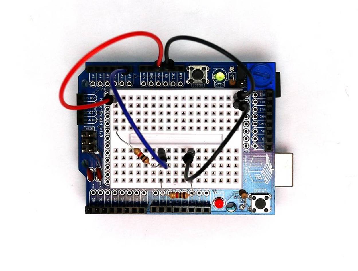
Figure 13-1. An Arduino Ohmmeter
Let’s Build an Arduino Ohmmeter
This gadget tests the resistance of electrical components. Place the unknown resistor you want to test in series with the reference resistor R1 connected to GND. The Arduino will calculate the resistance and display it on the Serial Monitor. The resistance of other electrical objects can be measured with the Arduino Ohmmeter as well. Building the Arduino Ohmmeter on a MakerShield protoboard makes the device small enough to carry to a friend’s house to check his electronic projects. Figure 13-2 shows the Fritzing diagram for the Arduino Ohmmeter.
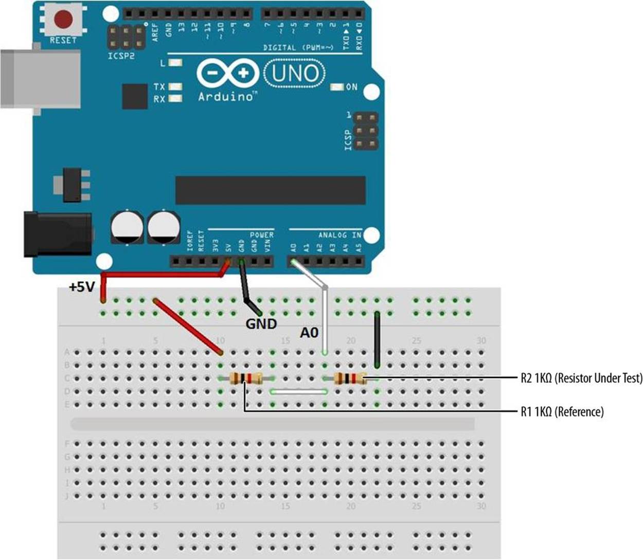
Figure 13-2. An Arduino Ohmmeter Fritzing diagram
Upload the Arduino Ohmmeter Sketch
It’s time to upload the Ohmmeter sketch to the Arduino. Example 13-1 reads the resistance of R2, and reports the result through the serial display. Here are the steps you’ll need to take:
1. Attach the Arduino to your computer using a USB cable.
2. Open the Arduino software and type Example 13-1 into the software’s text editor.
3. Upload the sketch to the Arduino.
Once the Ohmmeter sketch has been uploaded to the Arduino, place the unknown resistor (shown as R2 on the Frizting diagram) you want to test in series with the reference resistor R1 (1KΩ) connected to GND. The voltage across the R2 resistor and its resistance value will be displayed on the Serial Monitor. Figure 13-3 shows the output voltage (Vout) and the measured resistance of a 1KΩ resistor (R2) being displayed on the Serial Monitor.
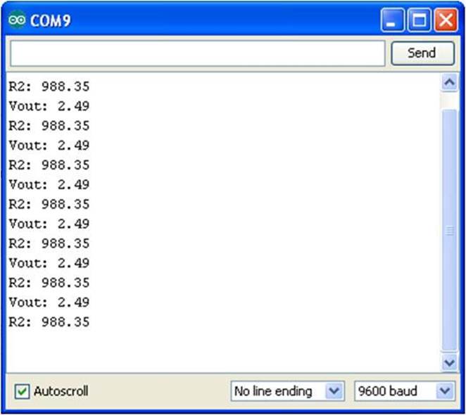
Figure 13-3. R2 and Vout measured and displayed on the Serial Monitor
Example 13-1. The Arduino Ohmmeter sketch
/*
Arduino Ohmmeter
*/
// set up pins on Arduino for LED and test lead
int analogPin = 0; // reads the resistance of R2
int raw = 0; // variable to store the raw input value
int Vin = 5; // variable to store the input voltage
float Vout = 0; // variable to store the output voltage
float R1 = 1000; // variable to store the R1 value
float R2 = 0; // variable to store the R2 value
float buffer = 0; // buffer variable for calculation
void setup()
{
Serial.begin(9600); // Set up serial
}
void loop()
{
raw = analogRead(analogPin); // reads the input pin
if(raw)
{
buffer = raw * Vin;
Vout = buffer /1024.0; // calculates the voltage on the input pin
buffer = (Vin / Vout) - 1;
R2 = R1 / buffer;
Serial.print("Vout: ");
Serial.println(Vout); // outputs the information
Serial.print("R2: "); //
Serial.println(R2); //
delay(1000);
}
}
TECH NOTE
The value of R1 is stored using a float variable type in the sketch. Change the value from 1000 (1KΩ) to a higher value when reading higher resistance values.
Circuit Theory
The operation of the Arduino Ohmmeter is based around the concept of the voltage divider. Two resistors are connected in series, and the reading is taken from where the two resistors join. The voltage measured at that point is the ratio of R2/(R1+R2) multiplied by the voltage in. For example, if R2 is 10K and R1 is 10K, then the ratio is 1/2; multiplying that by 5 volts returns 2.5 volts.
The Arduino Ohmmeter uses that relationship between voltage and resistance slightly differently. It knows that it started with 5 volts from the VCC pin. It also knows that the reference R1 has a value of 1K ohms. It then reads the divided voltage in at analog pin 0. Using those numbers, it is relatively easy to calculate the value of the object at R2.
A Fritzing electronic circuit schematic diagram of the Ohmmeter is shown in Figure 13-4. The Arduino Ohmmeter block diagram showing the connecting electronic components is shown in Figure 13-5. As a reminder, circuit schematic diagrams use electrical symbols for electronic components and are abbreviated drawings of Fritzing diagrams.
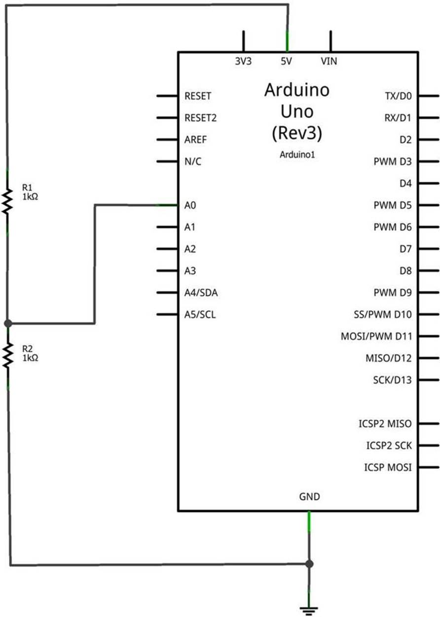
Figure 13-4. An Arduino Ohmmeter circuit schematic diagram

Figure 13-5. An Arduino Ohmmeter circuit block diagram
ELECTRICAL SAFETY TIP
Under no circumstance should the Ohmmeter be used to test powered electrical/electronic devices. For your safety and the protection of the Arduino and MakerShield, do not use the Ohmmeter to test any powered electrical/electronic devices!
Something to Think About
How can a small slide switch be added to select between two unknown resistors for measuring their resistance?
All materials on the site are licensed Creative Commons Attribution-Sharealike 3.0 Unported CC BY-SA 3.0 & GNU Free Documentation License (GFDL)
If you are the copyright holder of any material contained on our site and intend to remove it, please contact our site administrator for approval.
© 2016-2026 All site design rights belong to S.Y.A.