Make: Basic Arduino Projects - 26 Experiments with Microcontrollers and Electronics (2014)
Chapter 25. The Metronome
The “tick-tick-tick” of the metronome is the steady sound used to help musicians play music at a regular beat. In 1815, Johann Maelzel, a German inventor and engineer, made a swinging device for use as a tool for musicians to keep a steady tempo as they play their music. The metronome is a mechanical gadget that uses an adjustable weight attached to a pendulum rod. As the pendulum rod swings back and forth, the metronome makes a clicking sound. Today, Makers have made a variety of electronic metronomes that use speakers or LEDs to imitate the click and swinging motion of the mechanical pendulum. You can make your own metronome to impress family, friends, and the local Makerspace using a few electronic and electromechanical components from the Ultimate Microcontroller Pack. The Metronome is an awesome project to build because of the cool ticking sound and the homebrew pendulum rod swinging motion. The electronic and electromechanical components to build the Metronome project are shown in the Parts List. The assembled Metronome is shown in Figure 25-1.
Parts List
§ Arduino microcontroller
§ MakerShield kit
§ R1: 10KΩ potentiometer
§ P1: piezo buzzer
§ M1: DC servo motor
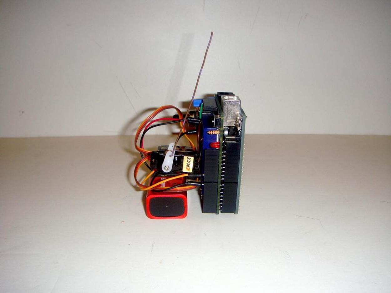
Figure 25-1. The Metronome
Let’s Build a Metronome
The Metronome is quite easy to build and it looks and sounds awesome when operating. The DC servo motor provides the swinging motion to a homebrew pendulum rod made from a piece of solid wire. The solid wire is threaded through the bottom hole of a servo arm. To secure the wire to the motor while in motion, the end of the wire passing through the bottom hole is wrapped around the servo arm. To complete the mechanical assembly of the servo motor, the homebrew pendulum rod (the solid wire) is stretched out, as shown in Figure 25-1. Next, the servo motor is attached to the breadboard using a piece of solid wire to prevent it from moving when the pendulum rod is swinging back and forth. The wire is wrapped around the servo motor. The free wire ends on each side of the servo motor are inserted into the breadboard (see Figure 25-2).
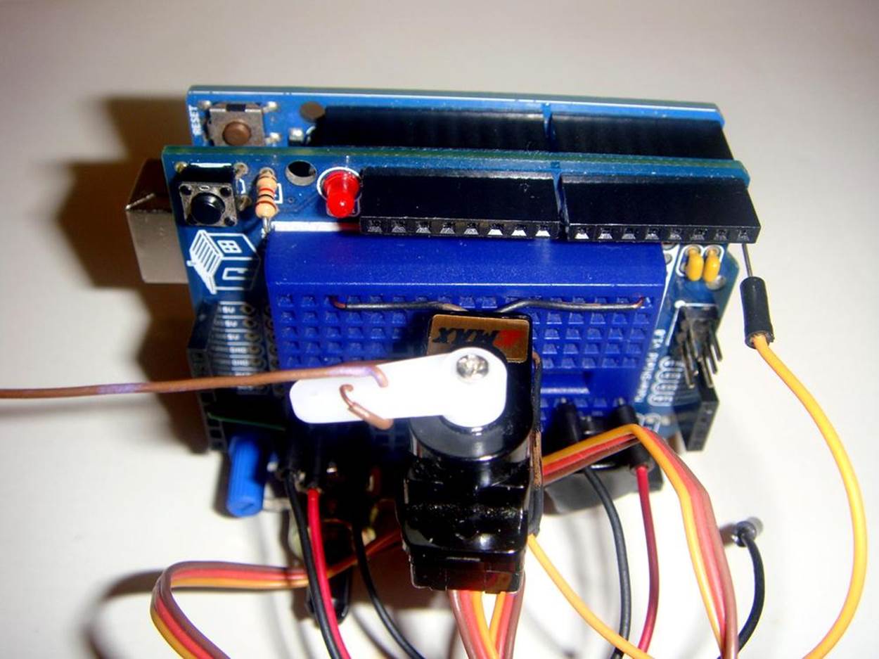
Figure 25-2. Servo motor attachment to breadboard: the free wire ends are inserted into the breadboard
The 10KΩ potentiometer is used as a volume control to adjust the sound level of the piezo buzzer. A cool trick used to make the “tick” sound, along with adjusting the volume, is to place a small piece of tape over the piezo buzzer. Figure 25-3 shows the location of the volume control, and the piezo buzzer with tape placed over it. The Fritzing wiring diagram for building the Metronome is shown in Figure 25-4. As with previous projects presented in this book, the MakerShield protoboard is a great prototyping tool to use in building this cool mini Metronome device. Its breadboarding area allows the piezo buzzer, potentiometer, and servo motor components to be wired to the Arduino microcontroller in a compact package.
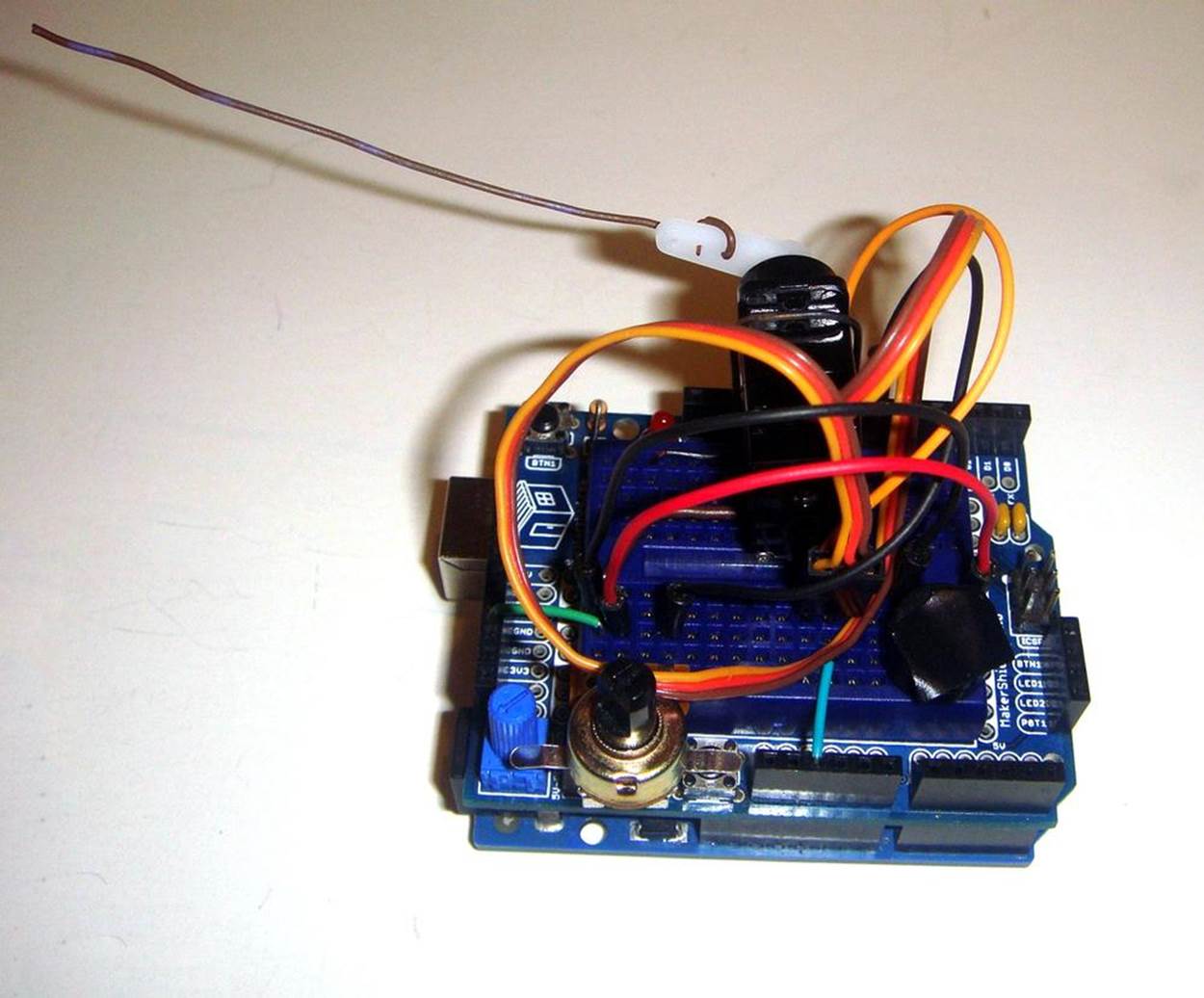
Figure 25-3. View of 10KΩ potentiometer (volume control) and piezo buzzer (with tape)
TECH NOTE
Make sure when placing the tape over the piezo buzzer that you do not completely silence it!
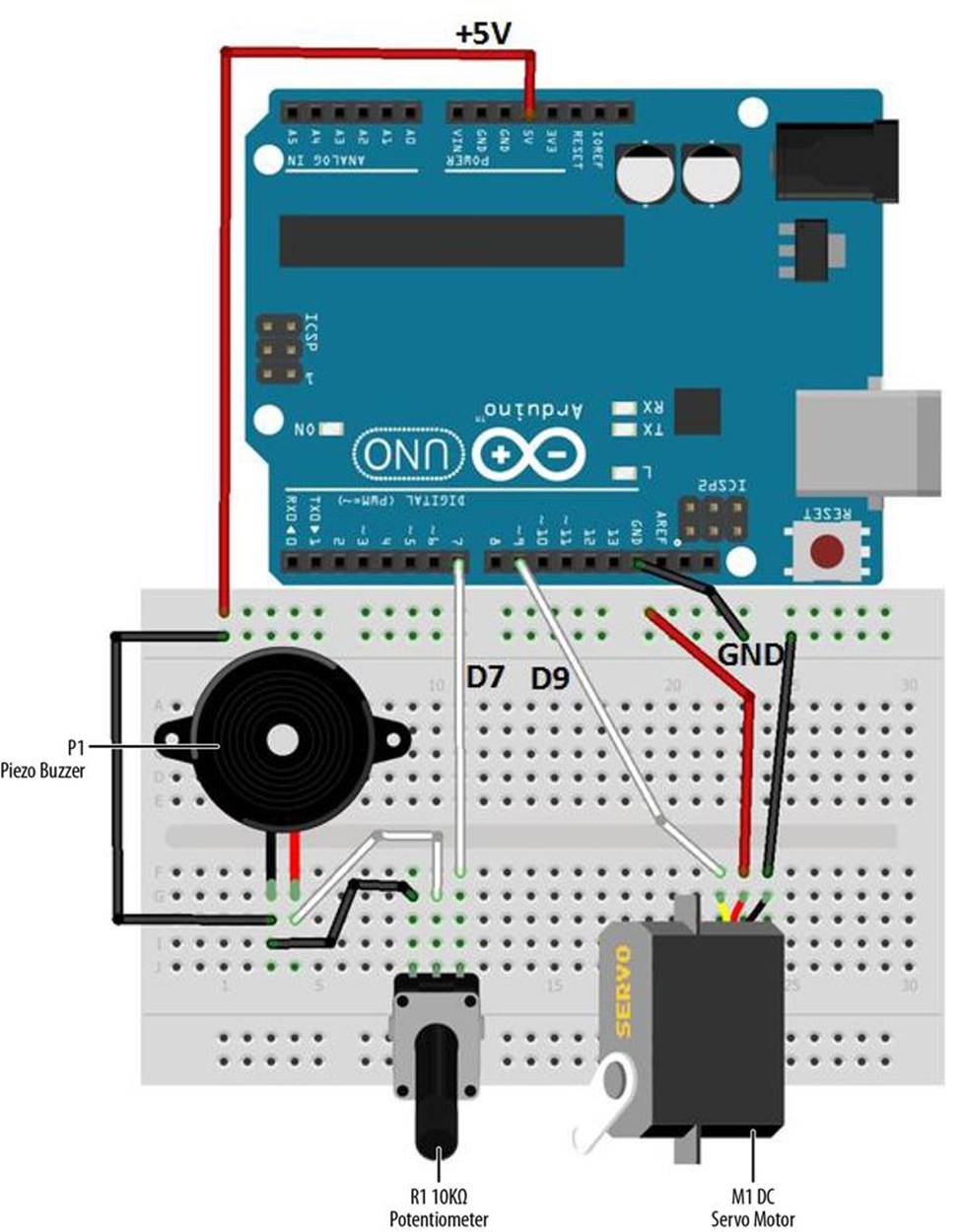
Figure 25-4. The Metronome Fritzing wiring diagram
Upload the Metronome Sketch
Before uploading Example 25-1 to the Arduino, check and correct any wiring errors on your breadboard using the Fritzing diagram shown in Figure 25-4. With the Metronome electrical circuit wired on the breadboard, now it’s time to upload the Arduino sketch. Here are the steps you’ll need to follow:
1. Attach the Arduino microcontroller to your computer using a USB cable.
2. Open the Arduino software and type Example 25-1 into the software’s text editor.
3. Upload the sketch to the Arduino microcontroller.
The Arduino microcontroller is now programmed with the Metronome sketch. The servo motor’s arm, with the homebrew pendulum rod, will begin to move back and forth. Also, with each pass of the pendulum rod, a “tick” sound can be heard from the Piezo buzzer. Figure 25-5 shows the completed Metronome in action.
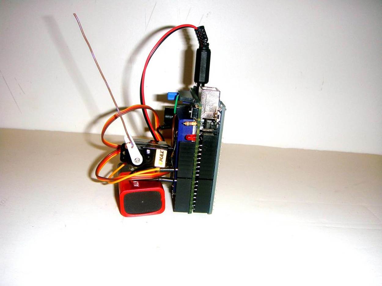
Figure 25-5. The Metronome in action
TECH NOTE
A piece of solid wire was used to make a pendulum rod. Cardboard and LEGO brick plates are good substitutes for a pendulum rod as well.
Example 25-1. The Metronome sketch
/*
Metronome sketch
The servo motor arm will swing back and forth with a tick sound coming
from a piezo buzzer.
31 August 2013
by Don Wilcher
*/
#include <Servo.h>
Servo myservo; // create servo object to control a servo
// a maximum of eight servo objects can be created
int pos = 0; // variable to store the servo position
int PBuzzer = 7; // piezo buzzer pin number
void setup()
{
myservo.attach(9); // attaches the servo on pin 9 to the servo object
pinMode(PBuzzer, OUTPUT);
}
void loop()
{
for(pos = 0; pos <=45; pos += 1) // goes from 0 degrees to 45 degrees
{ // in steps of 1 degree
if(pos==45){
digitalWrite(PBuzzer, LOW);
delay(15);
digitalWrite(PBuzzer, HIGH);
delay(15);
digitalWrite(PBuzzer, LOW);
delay(15);
}
myservo.write(pos); // go to position in variable 'pos'
delay(15); // waits 15ms to reach the position
}
for(pos = 45; pos>=1; pos-=1) // goes from 45 degrees to 0 degrees
{
if (pos==1){
digitalWrite(PBuzzer, LOW);
delay(15);
digitalWrite(PBuzzer, HIGH);
delay(15);
digitalWrite(PBuzzer, LOW);
delay(15);
}
myservo.write(pos); // go to position in variable 'pos'
delay(15); // waits 15ms to reach the position
}
}
The Metronome’s block diagram is shown in Figure 25-6. The block diagram shows the circuit component blocks and the electrical signal flow (current) for the Metronome. Also, the equivalent Fritzing electronic circuit schematic diagram of the Metronome is shown in Figure 25-7. Electrical/electronic engineers and technicians use them to design, build, and test cool interactive electronic products for games, testing equipment, robots, and automobiles.
TECH NOTE
In order for the tick sound and swinging motion to be synchronized, the delay(15) instruction is used throughout the Metronome sketch.
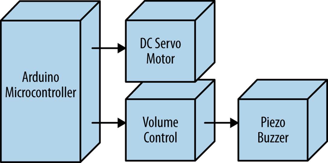
Figure 25-6. The Metronome block diagram
Something to Think About
How can you change the timing of the Metronome?
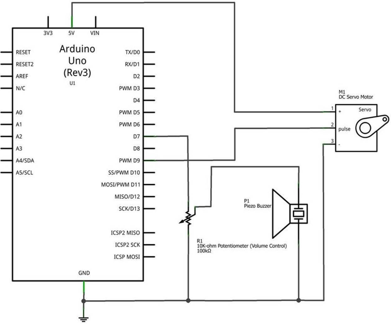
Figure 25-7. The Metronome Fritzing circuit schematic diagram
All materials on the site are licensed Creative Commons Attribution-Sharealike 3.0 Unported CC BY-SA 3.0 & GNU Free Documentation License (GFDL)
If you are the copyright holder of any material contained on our site and intend to remove it, please contact our site administrator for approval.
© 2016-2026 All site design rights belong to S.Y.A.