Make: Basic Arduino Projects - 26 Experiments with Microcontrollers and Electronics (2014)
Chapter 5. The Opposite Switch
The Arduino NOT Logic Gate
Computers use electrical signals to make basic decisions. By hard-wiring electric circuits in specific ways, you can actually see simple logic decision operations at work. Ordinary electronic parts, like electrical switches, resistors, and LEDs can make AND, OR, and NOT logic gates when wired together properly.
The first computer logic decision circuit you will build is a NOT gate. You will also learn how the Opposite Switch works in electrical/electronic and digital computer circuits by building an Arduino NOT Logic Gate. Figure 5-1 shows the Arduino NOT Logic Gate (the Opposite Switch) device. The Ultimate Microcontroller Pack has all of the electronic parts to build this cool digital electronics device.
Parts List
§ Arduino microcontroller
§ MakerShield kit
§ R1: 330 ohm resistor (orange, orange, brown stripes)
§ R2: 330 ohm resistor (orange, orange, brown stripes)
§ R3: 1KΩ resistor (brown, black, red stripes)
§ SW1: pushbutton switch
§ LED1: red LED
§ LED2: green LED
§ Battery1: 9VDC battery pack

Figure 5-1. The Arduino NOT Logic Gate
Circuit Theory
A NOT Logic Gate turns a TRUE signal into a FALSE signal. Let’s take the case of the ordinary household light switch: When you flip the light switch in your home UP, the light bulb turns on. Now, let’s mount the house light switch upside down. When you send an UP signal to the switch, the light bulb will turn off. When you send a DOWN signal to the switch, the light bulb turns on. To illustrate this basic FALSE-TRUE operation, Figure 5-2 shows a simple NOT Logic Gate circuit you can build and experiment with, using a few electronic components from the Ultimate Microcontroller Pack. After wiring the NOT Logic Gate circuit on the breadboard, the red LED will be on. Pressing the pushbutton switch will turn the red LED off.
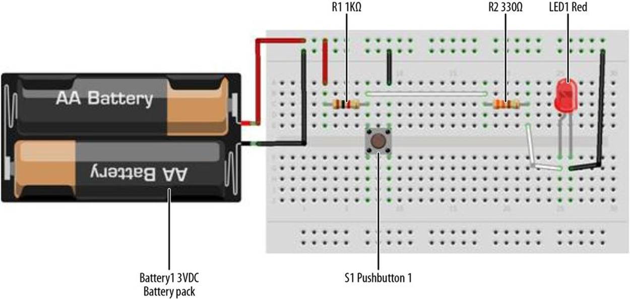
Figure 5-2. A simple NOT Logic Gate Fritzing wiring diagram
The Opposite Switch (aka the NOT Logic Gate)
In digital electronics, a special circuit symbol is used for the NOT Logic Gate consisting of a circle attached to the point of a triangle on its side. Figure 5-3 shows the digital electronics circuit symbol for the NOT Logic Gate.
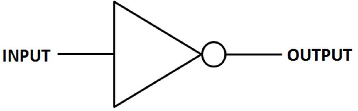
Figure 5-3. The NOT Logic Gate circuit symbol
In the Fritzing wiring diagram shown in Figure 5-2, the +3V battery provides the input binary data for the NOT Logic Gate and the electrical circuit output using an LED. With the switch open, the LED turns on. When the switch is closed, the LED turns off. Therefore, the purpose of the NOT Logic Gate circuit is to make a decision that is the opposite of the norm.
The NOT Logic Gate is traditionally used to invert a control signal used by smart machines like robots. To show the NOT Logic Gate’s decision operation graphically, a truth table (TT) is used; this is shown in Figure 5-4. A truth table is used in digital electronics to show the operation of computer logic circuits in a simple data table. The input column is the digital data or information applied to the logic gate. The output column shows the logic gate’s decision.
TECH NOTE
Another term for a NOT Logic Gate in digital electronics is “Inverter.”
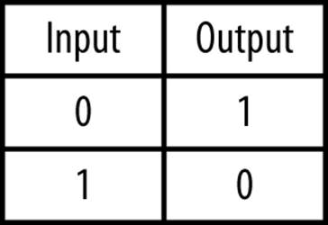
Figure 5-4. The NOT Logic Gate truth table
Build an Arduino NOT Logic Gate
We’re going to add an Arduino microcontroller to Figure 5-2 to control two LEDs using a computer program or sketch. You will wire the pushbutton switch with a 1KΩ resistor to pin D2 and two LEDs (red and green). The LEDs will be attached to pins D8 and D9. Figure 5-5 shows the Fritzing wiring diagram for this project. The NOT Logic Gate can easily be built using the MakerShield prototyping board. This prototyping board makes the device portable so you can carry it in your shirt pocket or toolbox to demonstrate it to family, friends, and the local Makerspace. Refer to Figure 5-1 for the MakerShield NOT Logic Gate device.
TECH NOTE
The MakerShield prototyping board is an awesome tool to create cool electronic gadgets like the ones in this book or on the Makezine/Arduino projects website.
Upload the Arduino NOT Logic Gate Sketch
With the Arduino NOT Logic Gate built on the MakerShield, it is time to upload the sketch. Example 5-1 operates the red and green LEDs using a pushbutton switch. Here are the steps you should follow:
1. Attach the Arduino to your computer using a USB cable.
2. Open the Arduino software and type Example 5-1 into the software’s text editor.
3. Upload the sketch to the Arduino.
4. Press the mini pushbutton switch for a moment.
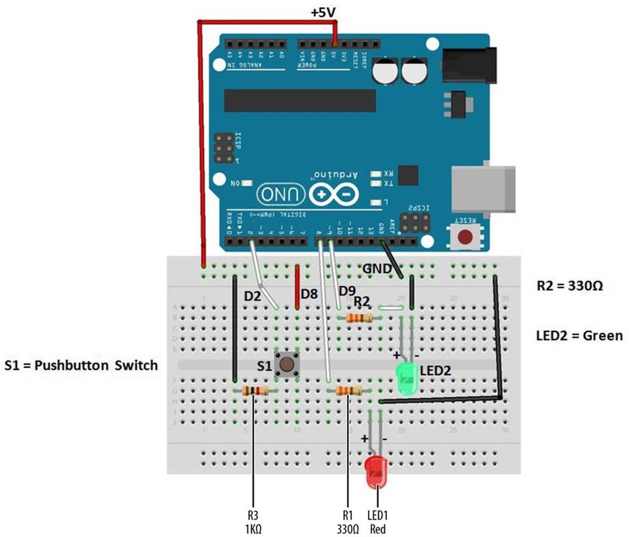
Figure 5-5. The NOT Logic Gate Fritzing wiring diagram
The Arduino NOT Logic Gate will turn the green LED on once the sketch has been uploaded to the microcontroller. Pressing the pushbutton switch will turn the green LED off and the red LED will be on. Figure 5-6 shows the Arduino NOT Logic Gate in operation. The green LED shows a TRUE output state when the pushbutton switch in not pressed. Pressing the pushbutton switch shows a FALSE output state by turning on the red LED. Also,the != in the Arduino sketch is the computer programming symbol for the logical NOT function.

Figure 5-6. The Arduino NOT Logic Gate: pressing the pushbutton switch turns on the red LED (FALSE output)
Example 5-1. The Arduino NOT Logic Gate sketch
/*
Arduino_NOT_Logic_Gate
This sketch demonstrates the NOT(Inverter) Logic Gate operation.
With the pushbutton switch not pressed (Logic LOW input), the green LED
(Logic HIGH output indicator) is on and the red LED (Logic LOW output
indicator) is off.
Pressing the pushbutton turns the green LED off and the red LED on.
11 September 2013
by Don Wilcher
*/
// set pin numbers:
int buttonPin = 2; // the number of the pushbutton pin
int LEDred = 8; // pin number for the red LED
int LEDgreen = 9; // pin number for the green LED
// variables will change:
int buttonStatus = 0; // variable for reading the pushbutton status
void setup() {
// initialize the LED pins as outputs:
pinMode(LEDred, OUTPUT);
pinMode(LEDgreen, OUTPUT);
// initialize the pushbutton pin as an input:
pinMode(buttonPin, INPUT);
}
void loop(){
// read the status of the pushbutton value:
buttonStatus = digitalRead(buttonPin);
// check if the pushbutton is not pressed
//
if (buttonStatus != HIGH) {
// turn green LED on:
digitalWrite(LEDgreen, HIGH);
// turn red LED off:
digitalWrite(LEDred, LOW);
}
else {
// turn green LED off:
digitalWrite(LEDgreen, LOW);
// turn red LED ON:
digitalWrite(LEDred, HIGH);
}
}
After the sketch has been successfully uploaded to the Arduino microcontroller, the green LED will be on and the red LED off. Press the pushbutton switch to toggle the on/off states of the LEDs. To test the NOT Logic Gate, use the truth table shown in Figure 5-7.
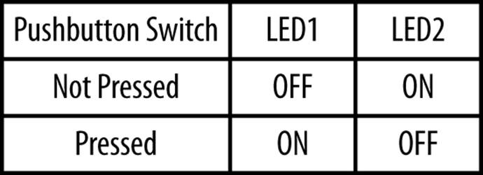
Figure 5-7. The Arduino NOT Logic Gate truth table
TROUBLESHOOTING TIP
If the LEDs do not turn based on the truth table, check your electrical wiring and make sure the LEDs are properly oriented.
The block diagram in Figure 5-8 shows the building blocks and the electrical signal flow for the Arduino NOT Logic Gate. Circuit schematic diagrams are used by electrical engineers to quickly build cool electronic devices. The equivalent circuit schematic diagram for the Arduino AND Logic Gate is shown in Figure 5-9.
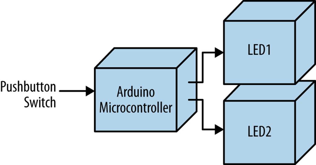
Figure 5-8. The Arduino NOT Logic Gate block diagram
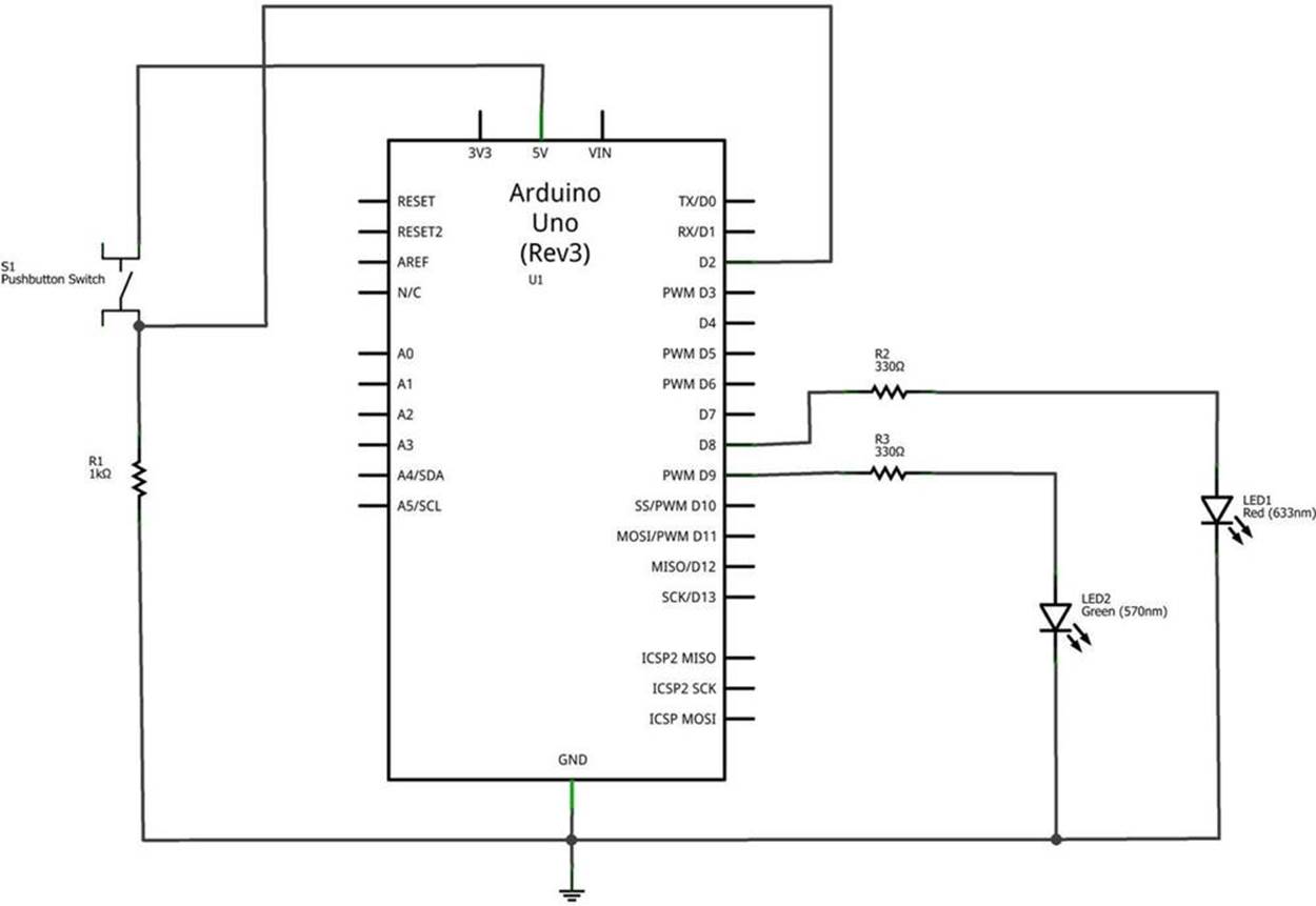
Figure 5-9. The Arduino NOT Logic Gate circuit schematic diagram
Something to Think About
How can a photocell be used to operate the Arduino NOT Logic Gate?
All materials on the site are licensed Creative Commons Attribution-Sharealike 3.0 Unported CC BY-SA 3.0 & GNU Free Documentation License (GFDL)
If you are the copyright holder of any material contained on our site and intend to remove it, please contact our site administrator for approval.
© 2016-2026 All site design rights belong to S.Y.A.