Make: Basic Arduino Projects - 26 Experiments with Microcontrollers and Electronics (2014)
Chapter 7. The OR Logic Gate
Two Pushbutton Switches in Parallel
The OR Logic Gate is the final basic computer circuit used to make simple decisions with electrical input signals. The OR Logic Gate is different from the AND circuit because the two pushbutton switches are connected in parallel (instead of in series as with the AND circuit). The OR Logic Gate’s output decision is based on either one or the other input being TRUE. In this chapter, you will learn about the OR Logic Gate by building an Arduino OR Logic Gate using one pushbutton switch and a photocell. Figure 7-1 shows the assembled Arduino OR Logic Gate. The Ultimate Microcontroller Pack has all of the electronic parts to build this cool digital computer circuit.
Parts List
§ Arduino microcontroller
§ MakerShield kit
§ S1: pushbutton switch
§ S2: pushbutton switch
§ R1: 1KΩ resistor (brown, black, red stripes)
§ R1: 330Ω resistor (orange, orange, brown stripes) for basic OR Logic Gate circuit
§ R2: photocell
§ R3: 1KΩ resistor (brown, black, red stripes)
§ R4: 330Ω resistor (orange, orange, brown stripes) for Arduino OR Logic Gate
§ LED1: red LED for basic OR Logic Gate Circuit (green LED for Arduino OR Logic Gate)
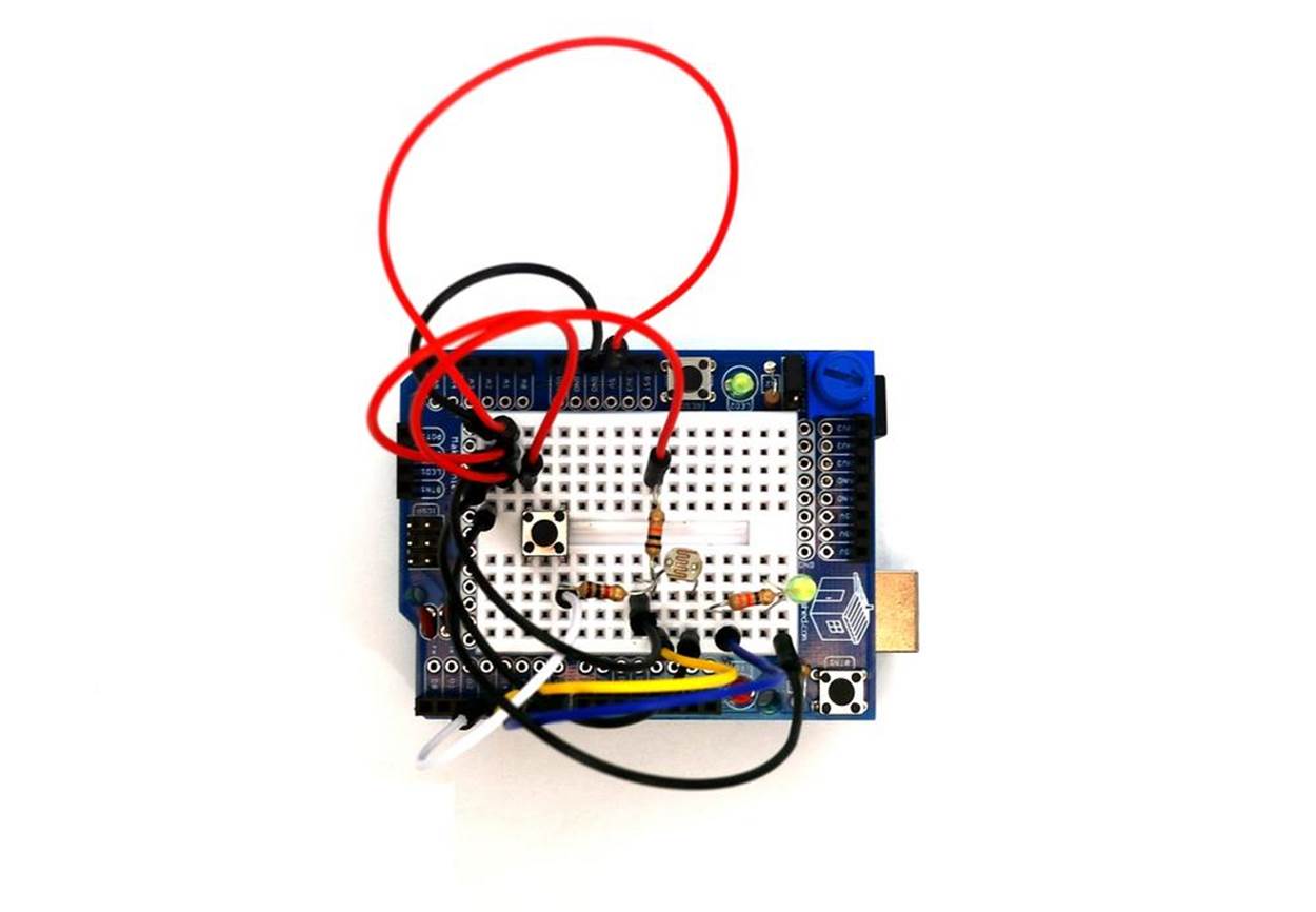
Figure 7-1. The assembled Arduino OR Logic Gate
TECH NOTE
When two or more electrical/electronic components are connected across one voltage source via separate paths, this is called a parallel circuit. In a parallel circuit, there are different ways that electricity can flow.
Circuit Theory
The OR Logic Gate is another computer circuit providing a TRUE output based on at least one input data value having a closed state. A basic OR Logic Gate electric circuit schematic diagram is shown in Figure 7-2. The circuit schematic diagram on the left shows one pushbutton switch closed and the other one open. The output for this pushbutton switch combination is TRUE, indicated by the LED being on. When both switches are open, as shown in the right circuit schematic diagram, the LED will be off. In summary, if at least one of the pushbutton switches is TRUE, the OR Logic Gate’s output will be TRUE. Therefore, the OR Logic Gate provides a TRUE output when either input is TRUE. This is different from the AND gate, which requires both inputs to be TRUE. To experiment with a basic OR Logic Gate circuit, the Fritzing wiring diagram shown inFigure 7-3 can be built on a breadboard.
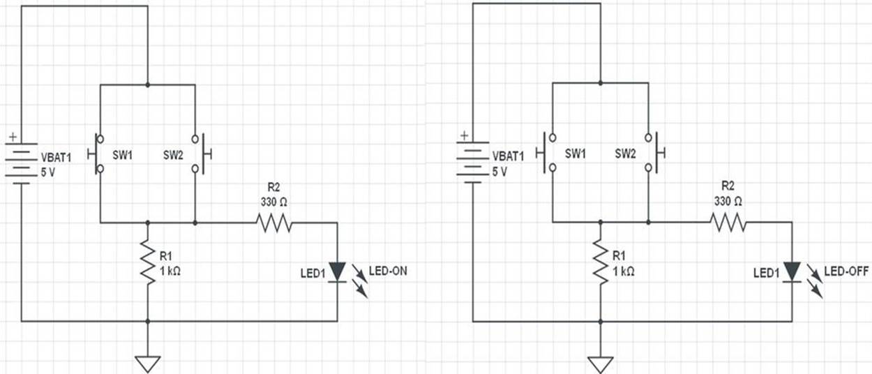
Figure 7-2. Circuit schematic diagram for the OR Logic Gate controlling an LED
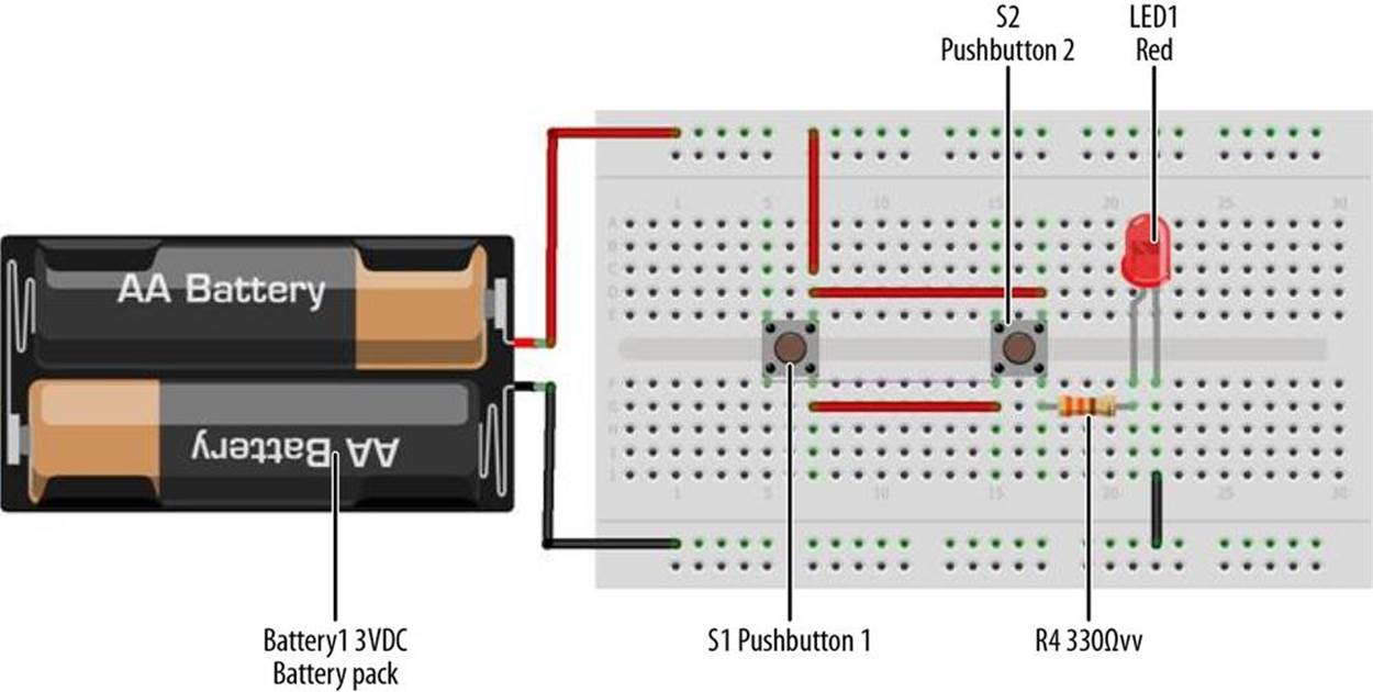
Figure 7-3. A basic OR Logic Gate circuit Fritzing wiring diagram
TECH NOTE
If you need an OR Logic Gate for an electronics project, simply wire two or more switches in parallel.
Just like the other logic gates discussed in Chapter 5 and Chapter 6, the OR Logic Gate has a special circuit symbol as well, shown in Figure 7-4. The truth table (TT) shows the logic gate operation. Figure 7-5 is an OR Logic Gate TT.
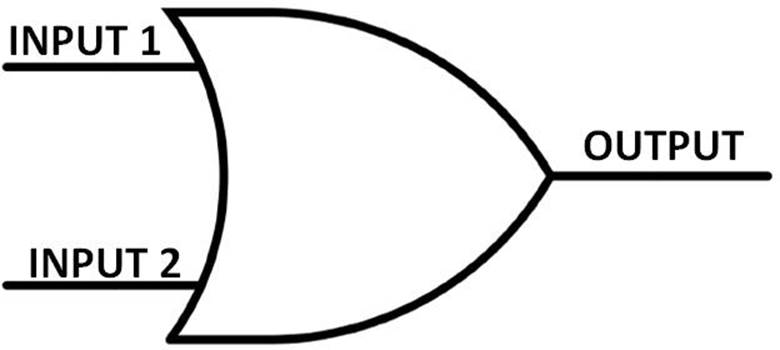
Figure 7-4. The OR Logic Gate circuit symbol
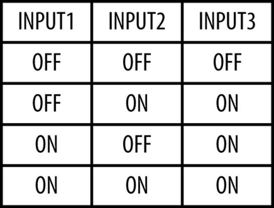
Figure 7-5. The OR Logic Gate Truth Table
The Arduino OR Logic Gate
You can build a digital computer OR Logic Gate circuit using the Arduino microcontroller and a few electronic components from the Ultimate Microcontroller Pack. The green LED turns on when either the pushbutton switch OR the photocell is TRUE. You can easily build the logic circuit using the Fritzing wiring diagram shown in Figure 7-6. You can build this basic digital computer circuit on MakerShield, as shown in Figure 7-1.
Did you notice that the Fritzing wiring diagram looks like the AND Logic Gate circuit of Chapter 6? That’s because it is. The cool thing about using an Arduino (or any other computer, really) is that often you can use the same physical circuit and make it do different things, simply by changing the computer code. In this case, either pressing the pushbutton switch OR placing your hand over the photocell will turn on the green LED.
This cool gadget can become an automatic LED night light. If your home loses power because of an electrical storm or the area substation is not operating, this device can function as an automatic light source. The photocell is electrically wired to detect darkness. When night falls (or when the power fails), the signal at pin D4 becomes TRUE, and the Arduino microcontroller turns on the green LED, as in Figure 7-7. Or, if you just want to turn the light on when it isn’t dark out, you can just hit the pushbutton switch. This makes the signal at pin D3 TRUE, which again causes the Arduino microcontroller to turn on the green LED.
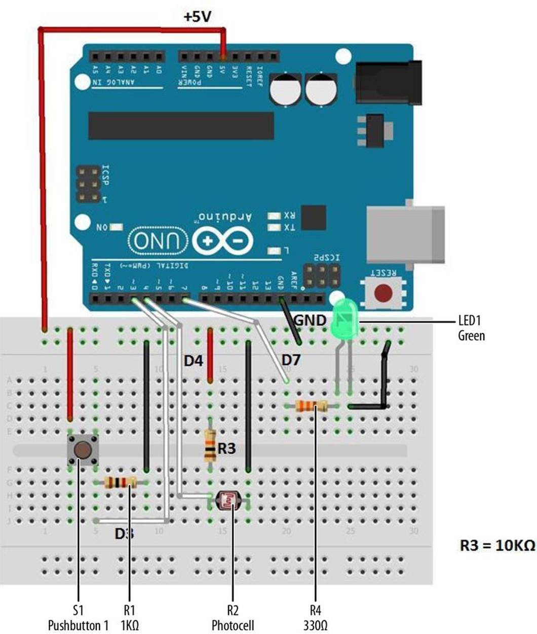
Figure 7-6. The Arduino OR Logic Gate Fritzing wiring diagram
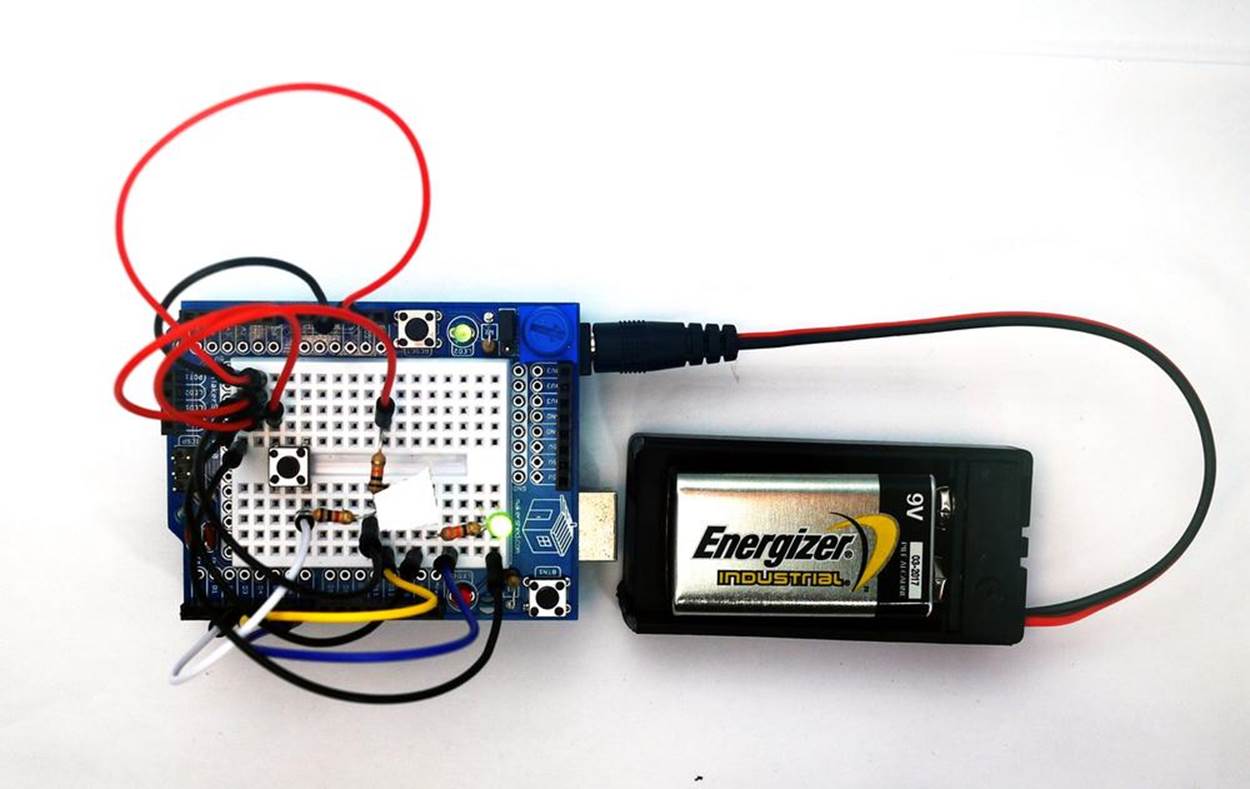
Figure 7-7. The LED is on: the photocell is covered with tape
TECH NOTE
The incandescent light bulb is slowly being replaced by LEDs because of their low power consumption and long life.
Upload the Arduino OR Logic Gate Sketch
With the Arduino AND Logic Gate built on the MakerShield, it is time to upload the sketch. Example 7-1 operates the green LED using a pushbutton switch and a photocell. Here are the steps you’ll need to take:
1. Attach the Arduino to your computer using a USB cable.
2. Open the Arduino software and type Example 7-1 into the software’s text editor.
3. Upload the sketch to the Arduino.
4. Press the mini pushbutton switch for a moment.
The Arduino OR Logic Gate will turn on the LED when the photocell is covered or the pushbutton switch is pressed. Releasing the pushbutton switch or placing a light on the photocell turns off the LED, because an OR condition (in which either switch is closed) no longer exists.
The Arduino does this by using the || operator in the if statement. || is the computer programming symbol for the logical OR function.
Example 7-1. The Arduino OR Logic Gate sketch
/*
The Arduino OR Logic Gate
Turns on an LED connected to digital
pin 7, when pressing either a pushbutton switch or covering a photocell
attached to pins 3 and 4.
27 Jan 2013
Revised 4 September 2013
by Don Wilcher
*/
// constants won't change; they're used here to
// set pin numbers:
int B = 3; // the number of the B pushbutton pin
int A = 4; // the number of the A pushbutton pin
const int Cout = 7; // the number of the LED pin
// variables will change:
int AStatus = 0; // variable for reading the A pushbutton status
int BStatus = 0;
void setup() {
// initialize the LED pin as an output:
pinMode(Cout, OUTPUT);
// initialize the pushbutton pins as inputs:
pinMode(B, INPUT);
pinMode(A, INPUT);
}
void loop(){
// read the state of the pushbutton value:
AStatus = digitalRead(A);
BStatus = digitalRead(B);
// check if the pushbuttons are pressed
// if it is, the buttonStatus is HIGH:
if (AStatus == HIGH || BStatus ==HIGH) {
// turn LED on:
digitalWrite(Cout, HIGH);
}
else {
// turn LED off:
digitalWrite(Cout, LOW);
}
}
After uploading the Arduino OR Logic Gate sketch to the Arduino microcontroller, the green LED is off. Pressing the pushbutton switch or placing your hand over the photocell will turn on the green LED. To completely test the Arduino OR Logic Gate’s operation, remember to use the TT shown in Figure 7-5.
The block diagram in Figure 7-8 shows the building blocks and the electrical signal flow for the Arduino OR Logic Gate. Circuit schematic diagrams are used by electrical engineers to quickly build cool electronic devices. The equivalent circuit schematic diagram for the Arduino OR Logic Gate is shown in Figure 7-9.
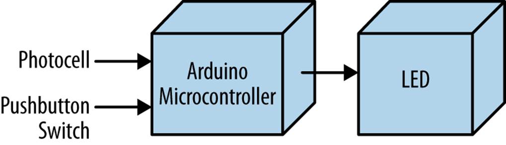
Figure 7-8. The Arduino OR Logic Gate block diagram
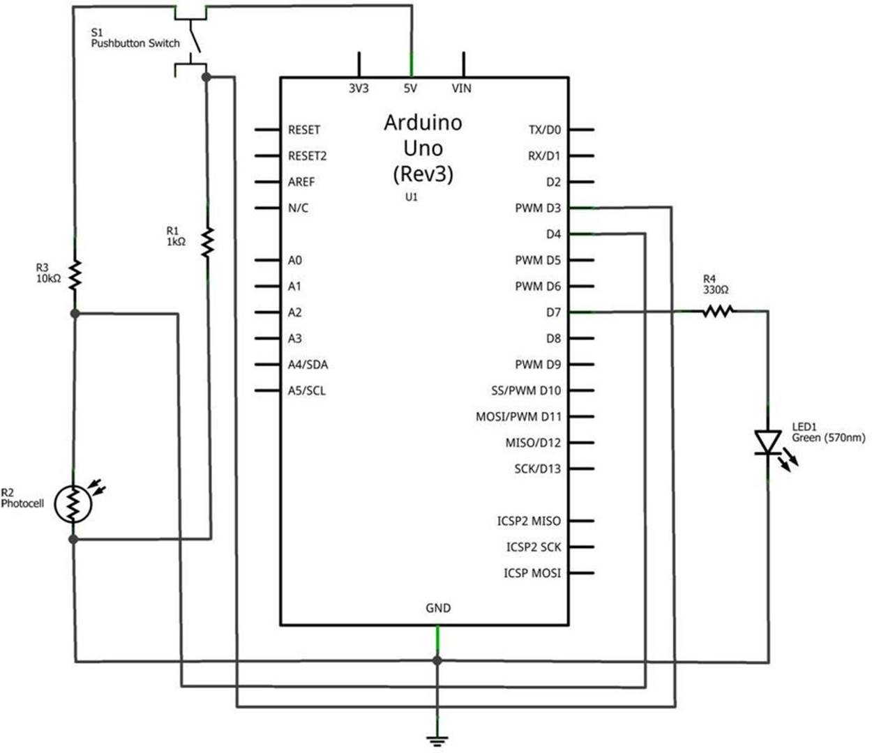
Figure 7-9. The Arduino OR Logic Gate circuit schematic diagram
TROUBLESHOOTING TIP
If the LED doesn’t light up after uploading the sketch to the Arduino microcontroller, check to see if it is connected to the correct output pin. Also, check to see if the LED has been connected in the proper orientation, with the short LED wire connected to GND.
Something to Think About
How can the Arduino OR Logic Gate be used to flash the green LED when the pushbutton switch or the photocell is TRUE?
All materials on the site are licensed Creative Commons Attribution-Sharealike 3.0 Unported CC BY-SA 3.0 & GNU Free Documentation License (GFDL)
If you are the copyright holder of any material contained on our site and intend to remove it, please contact our site administrator for approval.
© 2016-2026 All site design rights belong to S.Y.A.