Arduino: A Quick-Start Guide, Second Edition (2015)
Part II. Eleven Arduino Projects
Chapter 9. Tinkering with the Wii Nunchuk
One of the most entertaining electronic activities is simply tinkering: taking an existing product and turning it into something different or using it for an unintended purpose. Sometimes you have to open the product and void its warranty; other times you can safely make it part of your own project.
In this chapter, you’ll learn how to hijack a Nintendo Nunchuk controller. It’s a perfect candidate for tinkering: it comes with a three-axis accelerometer, an analog joystick, and two buttons, and it is very cheap (less than $20 at the time of this writing). Even better: because of its good design and its easy-to-access connectors, you can easily integrate it into your own projects.
You’ll use an ordinary Nunchuk controller and transfer the data it emits to our computer using an Arduino. You’ll learn how to wire it to the Arduino, how to write software that reads the controller’s current state, and how to build your own video game console. You don’t even need a Nintendo Wii to do all of this—you need only a Nunchuk controller (shown in Figure 26, A Nintendo Nunchuk controller).
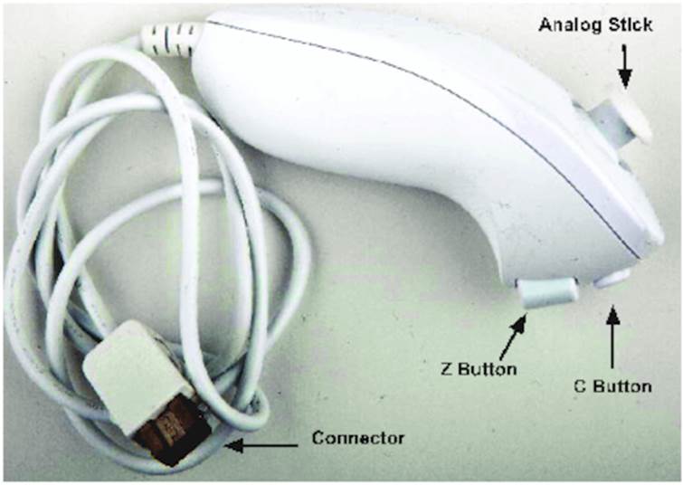
Figure 26. A Nintendo Nunchuk controller
What You Need
· An Arduino board, such as the Uno, Duemilanove, or Diecimila
· A USB cable to connect the Arduino to your computer
· A Nintendo Nunchuk controller
· Four wires
· The modified RCA cable you built in Chapter 8, Generating Video Signals with an Arduino
Wiring a Wii Nunchuk
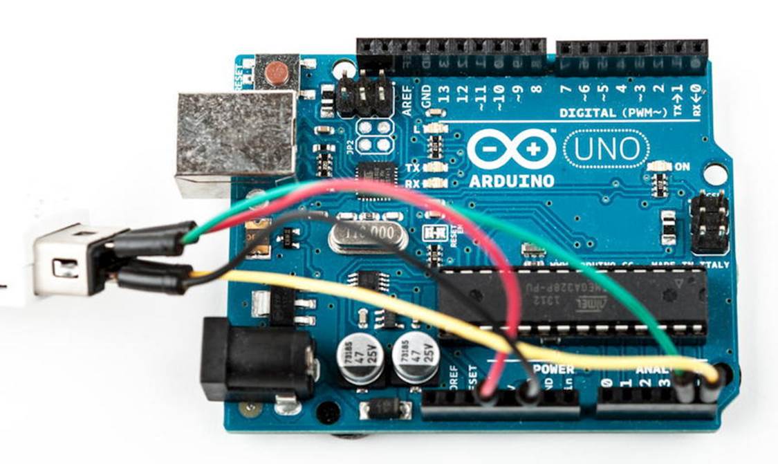
Wiring a Nunchuk to an Arduino really is a piece of cake. You don’t have to open the Nunchuk or modify it in any way. You only have to put four wires into its connector and then connect the wires to the Arduino:
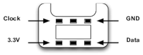
It has six connectors, but only four of them are active: GND, 3.3V, Data, and Clock. Here’s the pinout of a Nunchuk plug:
Put a wire into each connector and then connect the wires to the Arduino. Connect the data wire to analog pin 4 and the clock wire to analog pin 5. The GND wire has to be connected to the Arduino’s ground pin, and the 3.3V wire belongs to the Arduino’s 3.3V pin.
That’s really all you have to do to connect a Nunchuk controller to an Arduino. In the next section, you’ll see that the two wires connected to analog pins 4 and 5 are all we need to interface with the controller.
Talking to a Nunchuk
No official documentation shows how a Nunchuk works internally or how you can use it in a non-Wii environment. But some smart hackers and makers on the Internet invested a lot of time into reverse-engineering what’s happening inside the controller.
All in all, it’s really simple, because the Nunchuk uses the Two-Wire Interface (TWI), also known as I2C (Inter-Integrated Circuit) protocol.[84] It enables devices to communicate via a master/slave data bus using only two wires. You transmit data on one wire (Data), while the other synchronizes the communication (Clock).
The Arduino IDE comes with a library named Wire that implements the I2C protocol. It expects the data line to be connected to analog pin 4 and the clock line to analog pin 5. We’ll use it shortly to communicate with the Nunchuk, but before that, we’ll have a look at the commands the controller understands.[85]
To be honest, the Nunchuk understands only a single command: “Give me all your data.” Whenever it receives this command, it returns 6 bytes that have the following meanings:
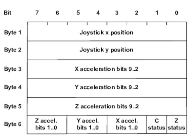
· Byte 1 contains the analog stick’s x-axis value, and in byte 2 you’ll find the stick’s y-axis value. Both are 8-bit numbers and range from about 29 to 225.
· Acceleration values for the x-, y-, and z-axes are three 10-bit numbers. Bytes 3, 4, and 5 contain their eight most significant bits. You can find the missing two bits for each of them in byte 6.
· Byte 6 has to be interpreted bit-wise. Bit 0 (the least significant bit) contains the status of the Z-button. It’s 0 if the button was pressed; otherwise, it is 1. Bit 1 contains the C-button’s status.
The remaining six bits contain the missing least significant bits of the acceleration values. Bits 2 and 3 belong to the x-axis, bits 4 and 5 belong to Y, and bits 6 and 7 belong to Z.
Now that you know how to interpret the data you get from the Nunchuk, you can start to build a Nunchuk class to control it.
Improve People's Lives with Tinkering
Because of its popularity, peripheral equipment for modern game consoles often is unbelievably cheap. Also, it’s no longer limited to classic controllers; you can buy things such as snowboard simulators or cameras. So, it comes as no surprise that creative people have built many interesting projects using hardware that was originally built for playing games.
An impressive and useful tinkering project is the EyeWriter.[86] It uses the PlayStation Eye (a camera for Sony’s PlayStation 3) to track the movement of human eyes.
A team of hackers built it to enable their paralyzed friend to draw graffiti using his eyes. Because of a disease, this friend, an artist, is almost completely physically paralyzed and can move only his eyes. With the EyeWriter, he can create amazing artwork again.
It’s not an Arduino project, but it’s definitely worth a look.
Building a Nunchuk Class
The interface of our Nunchuk class (and the main part of its implementation) looks as follows:
|
Tinkering/NunchukDemo/nunchuk.h |
|
|
Line 1 |
#ifndef __NUNCHUK_H__ |
|
- |
#define __NUNCHUK_H__ |
|
- |
#define NUNCHUK_BUFFER_SIZE 6 |
|
- |
|
|
5 |
class Nunchuk { |
|
- |
public: |
|
- |
void initialize(); |
|
- |
bool update(); |
|
- |
|
|
10 |
int joystick_x() const { return _buffer[0]; } |
|
- |
int joystick_y() const { return _buffer[1]; } |
|
- |
|
|
- |
int x_acceleration() const { |
|
- |
return ((int)(_buffer[2]) << 2) | ((_buffer[5] >> 2) & 0x03); |
|
15 |
} |
|
- |
|
|
- |
int y_acceleration() const { |
|
- |
return ((int)(_buffer[3]) << 2) | ((_buffer[5] >> 4) & 0x03); |
|
- |
} |
|
20 |
|
|
- |
int z_acceleration() const { |
|
- |
return ((int)(_buffer[4]) << 2) | ((_buffer[5] >> 6) & 0x03); |
|
- |
} |
|
- |
bool z_button() const { return !(_buffer[5] & 0x01); } |
|
25 |
bool c_button() const { return !(_buffer[5] & 0x02); } |
|
- |
|
|
- |
private: |
|
- |
void request_data(); |
|
- |
char decode_byte(const char); |
|
30 |
|
|
- |
unsigned char _buffer[NUNCHUK_BUFFER_SIZE]; |
|
- |
}; |
|
- |
|
|
- |
#endif |
This small C++ class is all you need to use a Nunchuk controller with your Arduino. It starts with a double-include prevention mechanism: it checks whether a preprocessor macro named __NUNCHUK_H__ has been defined already using #ifndef. If it hasn’t been defined, we define it and continue with the declaration of the Nunchuk class. Otherwise, the preprocessor skips the declaration, so you can safely include this header file more than once in your application.
In line 3, we create a constant for the size of the array we need to store the data the Nunchuk returns. We define this array in line 31, and in this case, we define the constant using the preprocessor instead of the const keyword, because array constants must be known at compile time in C++.
Then the actual declaration of the Nunchuk class begins. To initiate the communication channel between the Arduino and the Nunchuk, you have to invoke the initialize method once. Then you call update whenever you want the Nunchuk to send new data. You’ll see the implementation of these two methods shortly.
We have public methods for getting all of the attributes the Nunchuk returns: the x and y positions of the analog stick, the button states, and the acceleration values of the x-, y-, and z-axes. All of these methods operate on the raw data you can find in the buffer in line 31. Their implementation is mostly trivial, and it requires only a single line of code. Only the assembly of the 10-bit acceleration values needs some tricky bit operations (see Bit Operations).
At the end of the class declaration, you’ll find two private helper methods named request_data and decode_byte. We need them to implement the initialize and update methods:
|
Tinkering/NunchukDemo/nunchuk.cpp |
|
|
Line 1 |
#include <Arduino.h> |
|
- |
#include <Wire.h> |
|
- |
#include "nunchuk.h" |
|
- |
#define NUNCHUK_DEVICE_ID 0x52 |
|
5 |
|
|
- |
void Nunchuk::initialize() { |
|
- |
Wire.begin(); |
|
- |
Wire.beginTransmission(NUNCHUK_DEVICE_ID); |
|
- |
Wire.write((byte)0x40); |
|
10 |
Wire.write((byte)0x00); |
|
- |
Wire.endTransmission(); |
|
- |
update(); |
|
- |
} |
|
- |
|
|
15 |
bool Nunchuk::update() { |
|
- |
delay(1); |
|
- |
Wire.requestFrom(NUNCHUK_DEVICE_ID, NUNCHUK_BUFFER_SIZE); |
|
- |
int byte_counter = 0; |
|
- |
while (Wire.available() && byte_counter < NUNCHUK_BUFFER_SIZE) |
|
20 |
_buffer[byte_counter++] = decode_byte(Wire.read()); |
|
- |
request_data(); |
|
- |
return byte_counter == NUNCHUK_BUFFER_SIZE; |
|
- |
} |
|
- |
|
|
25 |
void Nunchuk::request_data() { |
|
- |
Wire.beginTransmission(NUNCHUK_DEVICE_ID); |
|
- |
Wire.write((byte)0x00); |
|
- |
Wire.endTransmission(); |
|
- |
} |
|
30 |
|
|
- |
char Nunchuk::decode_byte(const char b) { |
|
- |
return (b ^ 0x17) + 0x17; |
|
- |
} |
After including all of the libraries we need, we define the NUNCHUK_DEVICE_ID constant. I2C is a master/slave protocol; in our case, the Arduino will be the master, and the Nunchuk will be the slave. The Nunchuk registers itself at the data bus using a certain ID (0x52), so we can address it when we need something.
In initialize, we establish the connection between the Arduino and the Nunchuk by sending a handshake. In line 7, we call Wire’s begin method, so the Arduino joins the I2C bus as a master. (If you pass begin an ID, it joins the bus as a slave having this ID.) Then we’ll begin a new transmission to the device identified by NUNCHUCK_DEVICE_ID: our Nunchuk.
We send two bytes (0x40 and 0x00) to the Nunchuk, and then we end the transmission. This is the whole handshake procedure, and now we can ask the Nunchuk for its current status by calling update. In the following figure, we see the message flow between an Arduino and a Nunchuk.
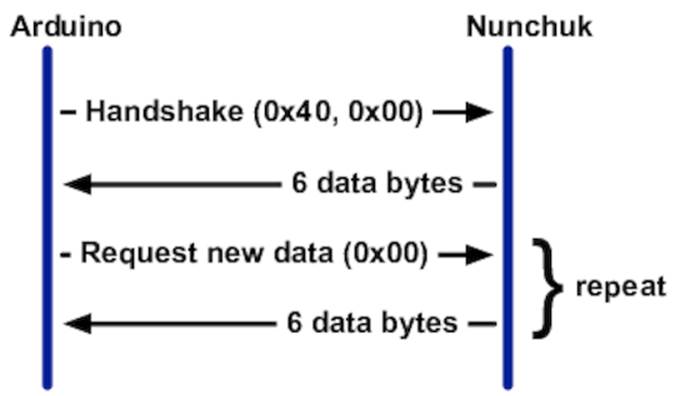
update first pauses for a millisecond to let things settle. Then we request six bytes from the Nunchuk, calling Wire.requestFrom. This doesn’t actually return the bytes, but we have to read them in a loop and fill our buffer. Wire.available returns the number of bytes available on the data bus, and Wire.read returns the current byte. We cannot use the bytes we get from the Nunchuk directly, because the controller obfuscates them. “Decrypting” them is easy, as you can see in decode_byte.
Finally, we call request_data to tell the Nunchuk to prepare new data. It transmits a single zero byte to the Nunchuk, which means “prepare the next six bytes.”
Before we actually use our Nunchuk class in the next section, take a look at the documentation of the Wire library. In the Arduino IDE’s menu, choose Help > Reference and click the Libraries link.
Scientific Applications Using Wii Equipment
Because of the Wii’s accuracy and low price, many scientists use the Wii for things other than gaming. Some hydrologists use it for measuring evaporation from a body of water.[87] Usually, you’d need equipment costing more than $500 to do that.
Some doctors at the University of Melbourne had a closer look at the Wii Balance Board, because they were looking for a cheap device to help stroke victims recover.[88] They published a scientific paper verifying that the board’s data is clinically comparable to that of a lab-grade “force platform” for a fraction of the cost.
Using Our Nunchuk Class
Let’s use the Nunchuk class to see what data the controller actually returns:
|
Tinkering/NunchukDemo/NunchukDemo.ino |
|
|
|
#include <Wire.h> |
|
|
#include "nunchuk.h" |
|
|
|
|
|
const unsigned int BAUD_RATE = 19200; |
|
|
Nunchuk nunchuk; |
|
|
|
|
|
void setup() { |
|
|
Serial.begin(BAUD_RATE); |
|
|
nunchuk.initialize(); |
|
|
} |
|
|
|
|
|
void loop() { |
|
|
if (nunchuk.update()) { |
|
|
Serial.print(nunchuk.joystick_x()); |
|
|
Serial.print(" "); |
|
|
Serial.print(nunchuk.joystick_y()); |
|
|
Serial.print(" "); |
|
|
Serial.print(nunchuk.x_acceleration()); |
|
|
Serial.print(" "); |
|
|
Serial.print(nunchuk.y_acceleration()); |
|
|
Serial.print(" "); |
|
|
Serial.print(nunchuk.z_acceleration()); |
|
|
Serial.print(" "); |
|
|
Serial.print(nunchuk.z_button()); |
|
|
Serial.print(" "); |
|
|
Serial.println(nunchuk.c_button()); |
|
|
} |
|
|
} |
No big surprises here: we define a global Nunchuk object and initialize it in the setup function. In loop, we call update to request the controller’s current status and output all attributes to the serial port.
Compile and upload the program, and then open the serial monitor and play around with the Nunchuk. Move the stick, move the controller, and press the buttons, and you should see something like this:
|
|
46 109 428 394 651 1 1 |
|
|
49 132 414 380 656 1 0 |
|
|
46 161 415 390 651 1 0 |
|
|
46 184 429 377 648 1 0 |
|
|
53 199 404 337 654 1 0 |
|
|
53 201 406 359 643 1 0 |
You have successfully connected a Nunchuk controller to your Arduino. It really isn’t rocket science, and in the next section you’ll learn how to use it to control your own video games.
The next time you buy a new piece of hardware, try to imagine how to use it in a different context. Often it’s easier than you think. Oh, and whenever you create a class such as our Nunchuk class, consider turning your code into a library and making it available on the Internet. (See Chapter 4, Building a Morse Code Generator Library, to learn how to create your own libraries.)
Creating Your Own Video Game Console
Now that you know how to generate video output and how to control the Wii Nunchuk, it seems natural to build your own little video game console. You only have to combine the Nunchuk circuit and the circuit for generating the video signal. See Figure 27, Circuit of our video game console.
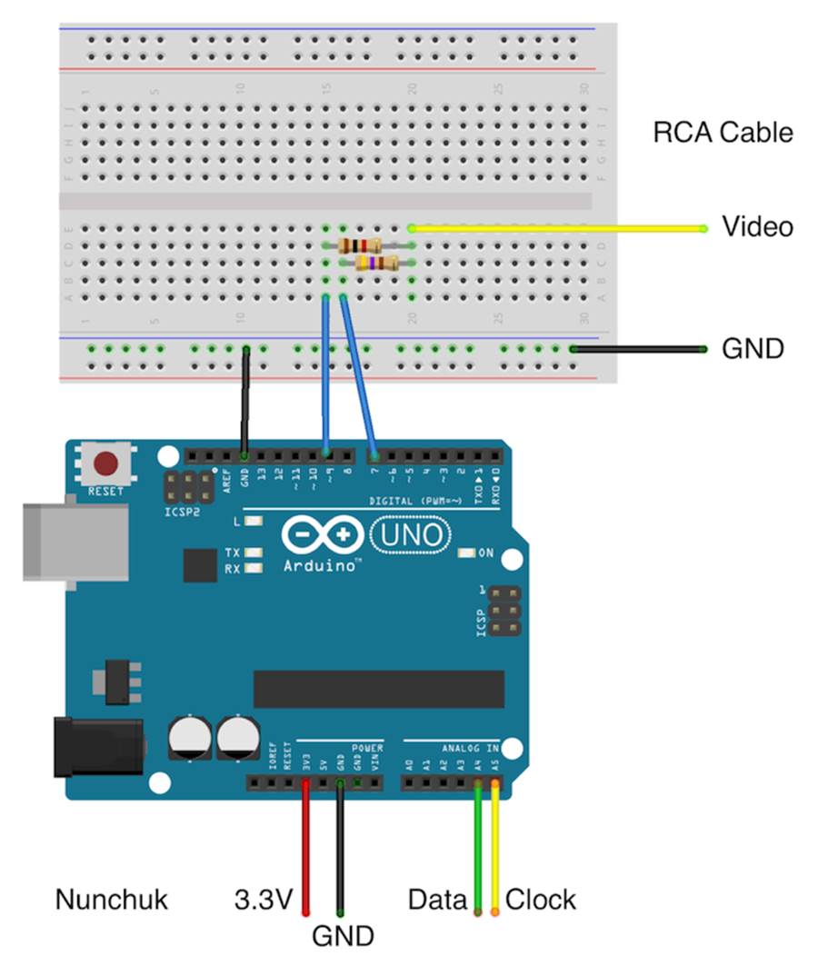
Figure 27. Circuit of our video game console
Note that you still don’t need a breadboard. Simply connect the Nunchuk to the Arduino as shown here and connect the RCA cable as shown here. That’s all you have to do to create your own video game console. Now let’s write some games for it.
Creating Your Own Video Game
TVout and our Nunchuk library are all we need to write entertaining games for our video game console. In this section we’ll build Pragduino, a simple game that demonstrates most of the skills you need to write more complex games.
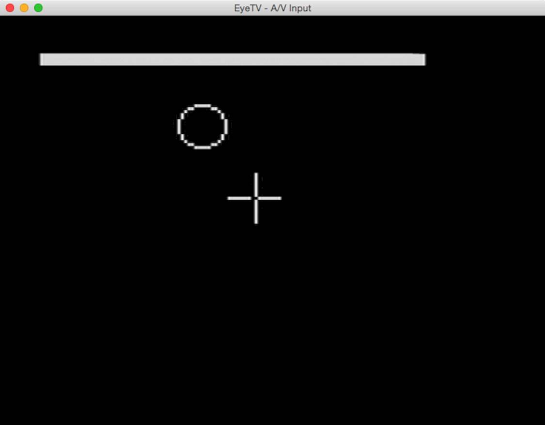
The player controls crosshairs using the Nunchuk’s analog stick and has to shoot circles using the Nunchuk’s Z button. The circles appear at random positions and stay there for 1.5 seconds. A status bar at the top of the screen shows how much time is left until the current circle disappears. The game ends after ten rounds, and the game’s goal is to hit as many circles as possible.
Before we dive into the game’s code, make sure you’ve installed the TVout library as described in Using the TVout Library. You also have to make the code of your Nunchuk library available. We haven’t turned it into a complete library in this chapter, but the book’s code archive contains an enhanced version. Download the book’s code from the book’s website and unzip it. Copy the code/Tinkering/Nunchuk directory to the libraries folder of your Arduino IDE. Alternatively, you can create a folder named Nunchuk in your IDE’s libraries folder and copy the nunchuk.h andnunchuk.cpp files to it. In both cases you have to restart the IDE.
That’s all the preparation you need to implement the Pragduino game, so let’s get started.
Setting the Stage for the Game
Most games need to handle a lot of global state, and Pragduino is no exception, so its code starts with a list of constant and variable definitions:
|
Tinkering/Pragduino/Pragduino.ino |
|
|
|
#include <Wire.h> |
|
|
#include <TVout.h> |
|
|
#include <fontALL.h> |
|
|
#include "nunchuk.h" |
|
|
|
|
|
const int WIDTH = 128; |
|
|
const int HEIGHT = 96; |
|
|
const int CH_LEN = 8; |
|
|
const int MAX_TARGET = 10; |
|
|
const int TARGET_LIFESPAN = 1500; |
As usual, we include all header files we need and define a few constants. WIDTH and HEIGHT contain the screen dimensions, and CH_LEN contains the length of a single crosshair element. (The crosshairs consist of four elements.) MAX_TARGET contains the number of circles you have to shoot, and TARGET_LIFESPAN contains a circle’s lifespan measured in milliseconds.
Next we define several global variables:
|
Tinkering/Pragduino/Pragduino.ino |
|
|
Line 1 |
TVout tv; |
|
- |
Nunchuk nunchuk; |
|
- |
|
|
- |
boolean up, down, left, right, c_button, z_button; |
|
5 |
int chx, chy; |
|
- |
int chvx, chvy; |
|
- |
int target_x, target_y, target_r; |
|
- |
unsigned int target_count; |
|
- |
unsigned int hits; |
|
10 |
unsigned long target_creation; |
|
- |
|
|
- |
enum GameState { |
|
- |
INTRO, STARTING, RUNNING, DONE |
|
- |
}; |
|
15 |
|
|
- |
GameState state; |
In game programming you often have to manage a lot of global variables—even in a small game like ours. First, we define a TVout instance named tv and a Nunchuk instance named nunchuk. After that, we define Boolean variables for all Nunchuk properties we’re interested in. They all work the same—we set up to true, for example, if the user pushes the Nunchuk’s analog stick upward.
chx and chy contain the current position of the crosshairs. chvx and chvy contain its X and Y velocity. Similarly, target_x and target_y contain the position of the current target. Because the target is a circle, we also need a radius, which we store in target_r.
target_count contains the number of targets we’ve created already, and in hits you can find the number of targets the player has hit so far. Targets disappear automatically after a short period of time, so we need a place to store the creation time of the current target. This place istarget_creation.
In line 12, we define an enumeration that lists our game’s potential states. If the game is in the INTRO state, it displays a title screen and waits for the player to press the Z button. If the player presses the Z button, the game changes to the STARTING state. It outputs a “READY?” message and waits for another button press to give the player some time to prepare.
The RUNNING state is where all the action is. In this state the game loop creates new targets, checks the player’s moves, and so on. After all targets have appeared, the game state changes to DONE. The player will see a game-over screen and the number of targets that he or she has hit.
We need to initialize all of these global variables whenever a new game starts. The following functions will do that:
|
Tinkering/Pragduino/Pragduino.ino |
|
|
|
void init_game() { |
|
|
up = down = left = right = c_button = z_button = false; |
|
|
chx = WIDTH / 2; |
|
|
chy = HEIGHT / 2; |
|
|
chvx = 1; |
|
|
chvy = 1; |
|
|
state = INTRO; |
|
|
target_count = 0; |
|
|
hits = 0; |
|
|
create_target(); |
|
|
} |
|
|
|
|
|
void create_target() { |
|
|
target_r = random(7, 11); |
|
|
target_x = random(target_r, WIDTH - target_r); |
|
|
target_y = random(target_r, HEIGHT - target_r); |
|
|
target_count++; |
|
|
target_creation = millis(); |
|
|
} |
The init_game function sets most of the global variables to constant values. create_target is a bit more interesting. It creates a new target at a random position and having a random size. We’ll use it later on in the game loop whenever we need to create a new target. Note that the function ensures that the target always stays within the screen’s bounds. Also, it uses the millis function to determine the target’s creation time.
Adding the Setup and Loop Functions
Like all Arduino programs our little game needs setup and loop functions:
|
Tinkering/Pragduino/Pragduino.ino |
|
|
Line 1 |
void setup() { |
|
- |
randomSeed(analogRead(A0)); |
|
- |
tv.begin(PAL, WIDTH, HEIGHT); |
|
- |
nunchuk.initialize(); |
|
5 |
init_game(); |
|
- |
} |
|
- |
|
|
- |
void loop() { |
|
- |
check_controls(); |
|
10 |
switch (state) { |
|
- |
case INTRO: intro(); break; |
|
- |
case STARTING: start_game(); break; |
|
- |
case RUNNING: update_game(); break; |
|
- |
case DONE: game_over(); break; |
|
15 |
} |
|
- |
tv.delay_frame(1); |
|
- |
} |
|
- |
|
|
- |
void check_controls() { |
|
20 |
up = down = left = right = c_button = z_button = false; |
|
- |
if (nunchuk.update()) |
|
- |
{ |
|
- |
if (nunchuk.joystick_x() < 70) |
|
- |
left = true; |
|
25 |
if (nunchuk.joystick_x() > 150) |
|
- |
right = true; |
|
- |
if (nunchuk.joystick_y() > 150) |
|
- |
up = true; |
|
- |
if (nunchuk.joystick_y() < 70) |
|
30 |
down = true; |
|
- |
c_button = nunchuk.c_button(); |
|
- |
z_button = nunchuk.z_button(); |
|
- |
} |
|
- |
} |
setup initializes the random number generator using some noise from analog pin A0. Then it initializes the screen and the Nunchuk, and finally it calls init_game to set all global variables to reasonable values.
The loop function calls check_controls to read the current state of the Nunchuk. Then it checks the game’s current state in a switch statement and delegates its work to the function responsible for handling the current state.
In line 16, loop calls a function of the TVout library you haven’t seen before. delay_frame waits for the beginning of the next vertical blanking interval—that is, for the moment when the TV set’s electron beam wanders from the bottom of the screen back to the top. We only want to wait for the beginning of the next frame, so we pass 1 to delay_frame. This is necessary to prevent flickering, because it ensures that the creation of the game’s graphics in memory stays in sync with the actual output on the screen.
Handling the Different Game States
Handling the game’s different states is vital, so we define separate functions for dealing with each game state:
|
Tinkering/Pragduino/Pragduino.ino |
|
|
Line 1 |
void intro() { |
|
- |
tv.select_font(font8x8); |
|
- |
tv.printPGM(28, 20, PSTR("Pragduino")); |
|
- |
tv.select_font(font6x8); |
|
5 |
tv.printPGM(16, 40, PSTR("A Pragmatic Game")); |
|
- |
tv.select_font(font4x6); |
|
- |
tv.printPGM(18, 74, PSTR("Press Z-Button to Start")); |
|
- |
if (z_button) { |
|
- |
state = STARTING; |
|
10 |
z_button = false; |
|
- |
delay(200); |
|
- |
} |
|
- |
} |
|
- |
|
|
15 |
void start_game() { |
|
- |
tv.clear_screen(); |
|
- |
tv.select_font(font8x8); |
|
- |
tv.printPGM(40, 44, PSTR("READY?")); |
|
- |
if (z_button) { |
|
20 |
init_game(); |
|
- |
state = RUNNING; |
|
- |
} |
|
- |
} |
|
- |
|
|
25 |
void game_over() { |
|
- |
tv.clear_screen(); |
|
- |
tv.select_font(font8x8); |
|
- |
tv.printPGM(28, 38, PSTR("Game Over")); |
|
- |
int x = (WIDTH - 7 * 8) / 2; |
|
30 |
if (hits > 9) |
|
- |
x = (WIDTH - 8 * 8) / 2; |
|
- |
tv.printPGM(x, 50, PSTR("Hits: ")); |
|
- |
tv.print(x + 6 * 8, 50, hits); |
|
- |
if (z_button) { |
|
35 |
state = STARTING; |
|
- |
z_button = false; |
|
- |
delay(200); |
|
- |
} |
|
- |
} |
|
40 |
|
|
- |
void update_game() { |
|
- |
tv.clear_screen(); |
|
- |
tv.draw_circle(target_x, target_y, target_r, WHITE); |
|
- |
move_crosshairs(); |
|
45 |
draw_crosshairs(); |
|
- |
check_target(); |
|
- |
if (target_count == MAX_TARGET + 1) { |
|
- |
state = DONE; |
|
- |
z_button = false; |
|
50 |
delay(200); |
|
- |
} |
|
- |
} |
The intro, start_game, and game_over functions are very similar. They print a message to the screen, then they wait for a Z button press. If the Z button was pressed, they move to the next state. Before they move to the next state, they set z_button to false and wait for 200 milliseconds. This is necessary to debounce the Z button.
All three functions use yet another TVout method. Look at line 3, for example. Here we use TVout’s printPGM method. It works like the regular print method, but it reads the string to be output from the Arduino’s flash memory and not from its precious SRAM. For applications that display a lot of constant messages, this can save a lot of memory.
To transfer the string into flash memory, we use the PSTR macro. It ensures that the strings we output using printPGM will be copied to flash memory when the program gets compiled.
Writing the Game Loop
The most central function of our game is update_game. It implements the actual game loop and first clears the screen by calling clear_screen. Then it uses draw_circle to draw the current target. move_crosshairs calculates the new position of the crosshairs depending on the player’s movement. draw_crosshairs outputs the crosshairs to the screen.
check_target determines the state of the current target—in other words, it checks whether the user has hit the target, whether the target has been on the screen for too long, or whether nothing special has happened. If all targets have been shown already, the game is over.
To control the crosshairs, we use the following helper functions:
|
Tinkering/Pragduino/Pragduino.ino |
|
|
|
void move_crosshairs() { |
|
|
if (left) chx -= chvx; |
|
|
if (right) chx += chvx; |
|
|
if (up) chy -= chvy; |
|
|
if (down) chy += chvy; |
|
|
|
|
|
if (chx <= CH_LEN) |
|
|
chx = CH_LEN + 1; |
|
|
if (chx >= WIDTH - CH_LEN) |
|
|
chx = WIDTH - CH_LEN - 1; |
|
|
if (chy <= CH_LEN) |
|
|
chy = CH_LEN + 1; |
|
|
if (chy >= HEIGHT - CH_LEN) |
|
|
chy = HEIGHT - CH_LEN - 1; |
|
|
} |
|
|
|
|
|
void draw_crosshairs() { |
|
|
tv.draw_row(chy, chx - CH_LEN, chx - 1, WHITE); |
|
|
tv.draw_row(chy, chx + 1, chx + CH_LEN, WHITE); |
|
|
tv.draw_column(chx, chy - CH_LEN, chy - 1, WHITE); |
|
|
tv.draw_column(chx, chy + 1, chy + CH_LEN, WHITE); |
|
|
} |
move_crosshairs checks all global variables related to the current Nunchuk state. It updates the position of the crosshairs depending on the variable values. Then it ensures that the crosshairs stay within the screen’s bounds.
The draw_crosshairs function actually draws the crosshairs on the screen. Instead of using a bitmap to draw the crosshairs, we use two new TVout methods. draw_row outputs a horizontal line, and we use it to output the two horizontal lines of the crosshairs. Similarly, we use draw_column to draw the two vertical lines. We leave the pixel at the crossing point empty to make the crosshairs look a bit nicer.
You might wonder why we didn’t use a bitmap. The problem with bitmaps is that they don’t look nice when they overlap. Even if the bitmap looks like crosshairs, it still is a square. If you move a crosshairs bitmap over a circle, the bitmap will hide a big part of the circle’s pixels.
To complete the game’s source code, we need two functions for managing the targets:
|
Tinkering/Pragduino/Pragduino.ino |
|
|
|
bool target_hit() { |
|
|
if (z_button) |
|
|
return (target_x - chx) * (target_x - chx) + |
|
|
(target_y - chy) * (target_y - chy) < target_r * target_r; |
|
|
return false; |
|
|
} |
|
|
|
|
|
void check_target() { |
|
|
if (target_hit()) { |
|
|
hits++; |
|
|
create_target(); |
|
|
} |
|
|
int remaining_time = millis() - target_creation; |
|
|
if (remaining_time >= TARGET_LIFESPAN) { |
|
|
create_target(); |
|
|
} |
|
|
int w = map(TARGET_LIFESPAN - remaining_time, 0, TARGET_LIFESPAN, 0, WIDTH); |
|
|
tv.draw_rect(0, 0, w, 3, WHITE, WHITE); |
|
|
} |
target_hit checks whether the player has hit the current target. This can only happen if the player presses the Z button. If this is the case, we use a simple distance calculation to see whether the crosshairs are in the circle.
To manage the current target’s lifecycle, we use check_target. If the target was hit, we increment the hits counter and create the next target. After that, we calculate the time the current target will stay on the screen unless it gets hit. If this time is greater than the target’s lifespan, we create a new target. At the end of the function, we turn the remaining time into a status bar at the top of the screen.
With less than 200 lines of code, you’ve written a complete game for your new video game console. It’s definitely not a blockbuster, but it’s actually fun and a great opportunity to learn about the very basics of game programming.
Also, it should give you enough confidence to implement more advanced games. You can find a lot of classic games on the web that use nearly the same hardware we used in this chapter.[89]
What If It Doesn’t Work?
From a maker’s perspective, this chapter is an easy one. Still, things can go wrong, especially with the wiring. Make sure you’ve connected the right pins on the Arduino and on the Nunchuk. Also check that the wires tightly fit into the Nunchuk’s and the Arduino’s sockets. When in doubt, use wire with a larger diameter.
Also, check What If It Doesn’t Work?, for all things that can go wrong when generating video signals with the Arduino.
Exercises
· Rewrite the game we implemented in Chapter 7, Writing a Game for the Motion-Sensing Game Controller , so it supports the Nunchuk controller. It should support both the analog stick and the accelerometer. Perhaps you can switch between them using the Nunchuk buttons.
· Tinkering with Nintendo’s Wii Motion is more complicated.[90] But it’s a nice and cheap way to sharpen your tinkering skills.
· The TVout library has basic audio support. Connect a piezo buzzer to digital pin 11 and use the tone and noTone functions to add sound capabilities to the video game console. Also, add some sound effects to Pragduino.
Footnotes
|
[84] |
http://en.wikipedia.org/wiki/I2c |
|
[85] |
At http://todbot.com/blog/2010/09/25/softi2cmaster-add-i2c-to-any-arduino-pins/, you can find a library that allows you to use any pair of pins for I2C communication. |
|
[86] |
http://www.eyewriter.org/ |
|
[87] |
http://www.wired.com/wiredscience/2009/12/wiimote-science/ |
|
[88] |
http://www.newscientist.com/article/mg20527435.300-wii-board-helps-physios-strike-a-balance-after-strokes.html |
|
[89] |
See http://nootropicdesign.com/hackvision/games.html. |
|
[90] |
http://randomhacksofboredom.blogspot.com/2009/07/motion-plus-and-nunchuck-together-on.html |
All materials on the site are licensed Creative Commons Attribution-Sharealike 3.0 Unported CC BY-SA 3.0 & GNU Free Documentation License (GFDL)
If you are the copyright holder of any material contained on our site and intend to remove it, please contact our site administrator for approval.
© 2016-2026 All site design rights belong to S.Y.A.