Arduino: A Quick-Start Guide, Second Edition (2015)
Part III. Appendixes
Appendix 1. Electronics and Soldering Basics
You didn’t need a lot of theory or background to create your first Arduino projects. But it’s a good idea to learn about electricity and about soldering if you want to build bigger and more sophisticated projects.
In this appendix, you’ll learn the basics of electricity, and you’ll learn about Ohm’s law, which is probably the most important law in electronics. Also, you’ll learn more about resistors, and you’ll see that soldering isn’t as difficult as it might seem.
Current, Voltage, and Resistance
To build your first projects with the Arduino, you didn’t need to know much about electricity. But at some point, you’ll need to understand what current, voltage, and resistance are all about. For example, you already know that you always have to put a resistor in front of an LED, but you might not know exactly why, and you might not know how to calculate the resistor’s size for a given LED. Let’s remedy that.
Electrical Circuits
An electrical circuit resembles a water circuit in many respects. In the following figure,[141] you can see a water circuit on the left and an electrical circuit on the right. Isn’t it fascinating how similar they are and that you can even find a connection between them when you use a water-driven dynamo that acts as a power supply? Let’s take a closer look at their most important attributes.
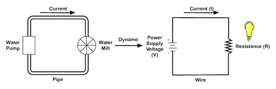
While water flows in a water circuit, electrons flow in an electrical circuit. Voltage is electricity’s equivalent of water pressure and is measured in volts (V). Voltage is the initial cause for a current, and the higher the voltage, the faster the current flows.
In electronics, current is the amount of electricity flowing through an electric line. It is the equivalent of the actual flow of water in a water circuit. While we measure the water flow in liters per minute, we measure current in amperes. One ampere means that approximately 6.24 × 10¹⁸electrons are flowing per second.
Every component in a circuit—be it water or electricity—resists some amount of current. In a water circuit, it’s the pipes the water is flowing through or perhaps a water mill. In an electrical circuit, it is the wire or a light bulb. Resistance is an important physical phenomenon that is closely related to current and voltage. We measure it in ohms, and its official symbol is Ω.
The German physicist Georg Ohm found that current depends on voltage and resistance. He postulated the following form that we call Ohm’s law today (we use I as the current’s letter for historical reasons. In the past, it stood for inductance):
· I (current) = V (voltage) / R (resistance)
This is equivalent to the following:
· R (resistance) = V (voltage) / I (current)
· V (voltage) = R (resistance) × I (current)
So, for two given values, you can calculate the third one. Ohm’s law is the only formula you’ll absolutely have to learn when learning electronics. When working with LEDs, it helps you calculate the size of the resistor you need.
If you look at an LED’s data sheet, you will usually find two values: a forward voltage and a current rating. The forward voltage usually is between 1.8V and 3.6V, and the maximum current often is 20 mA (milliamperes). Let’s say we have an LED with a maximum of 2.5 volts and a safe current of 20 mA. We also assume that we have a power supply delivering 5 volts (as most Arduinos do). What’s the right size of the resistor we need to put in front of the LED?
We have to make sure that the resistor takes 5 – 2.5 = 2.5 volts from the circuit, so only 2.5 volts are left for the LED. This value is called voltage drop. Also, we want a maximum of 20 mA to flow through the LED. This implies that a maximum of 20 mA (0.02 A) should flow through our resistor also.
Now that we know that 2.5V and 0.02 A should pass the LED, we can use Ohm’s law to calculate the resistance R:
R = V / I
In our case, we have the following:
R = 2.5V / 0.02A = 125Ω
This means we need a 125Ω resistor for our LED. If you do not have a 125Ω resistor, use a bigger one, such as 150Ω or 220Ω. It will still protect the LED and only slightly decrease its brightness. That’s because we’d decrease the current even more:
I = 2.5V / 150Ω = 17mA
I = 2.5V / 220Ω = 11mA
Resistors
You’ll hardly ever find an electronics project that doesn’t need resistors. So, you’ll need them often and should get more familiar with them. Usually you’ll use carbon or metal resistors. Metal resistors are more precise and don’t create so much noise, but carbon resistors are cheaper. In simple circuits, it usually doesn’t matter which type you use.
The most important attribute of a resistor is its resistance value that is measured in ohms. Only a few vendors actually print this value on the resistor, because resistors are small parts, and it’s hard to read text that is small enough to fit on them. So, they use a trick and encode the value using colored stripes.
Usually you find four or five stripes on a resistor (at least on through-hole parts; SMD resistors don’t have them). One of them is separated from the others by a gap. (See the following figure.) The separate stripe is on the right side of the resistor, and it tells you about the resistor’s accuracy. Gold stands for an accuracy of ±5 percent, silver stands for ±10 percent, and no stripe means ±20 percent. Using the remaining stripes, you can calculate the resistor value.
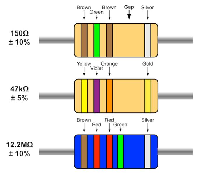
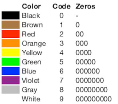
You read the stripes from left to right, and every color stands for a digit. (See the following figure.) The rightmost stripe—that is, the third or fourth one—stands for an amount of zeros to be added to the preceding digits. In the following figure, you can see three examples:
· On the first resistor we find four stripes: brown (1), green (5), brown (1 zero), silver (±10%). That means we have a resistor value of 150Ω.
· The second resistor has four stripes again: yellow (4), violet (7), orange (3 zeros), gold (±5%). So, this resistor has a value of 47000Ω = 47kΩ.
· The third resistor has five stripes: brown (1), red (2), red (2), green (5 zeros), silver (±10%), so the value is 12,200,000Ω = 12.2MΩ.
In the beginning, the color coding seems to be complicated, but you’ll get used to it quickly. Also, you can find countless tools for determining resistor values on the Internet.[142]
For the book’s projects, this is all the theory of electricity you need to know. To learn more about electronics, have a look at Make: Electronics [Pla10] or at http://lcamtuf.coredump.cx/electronics/, for example.
Learning How to Use a Wire Cutter
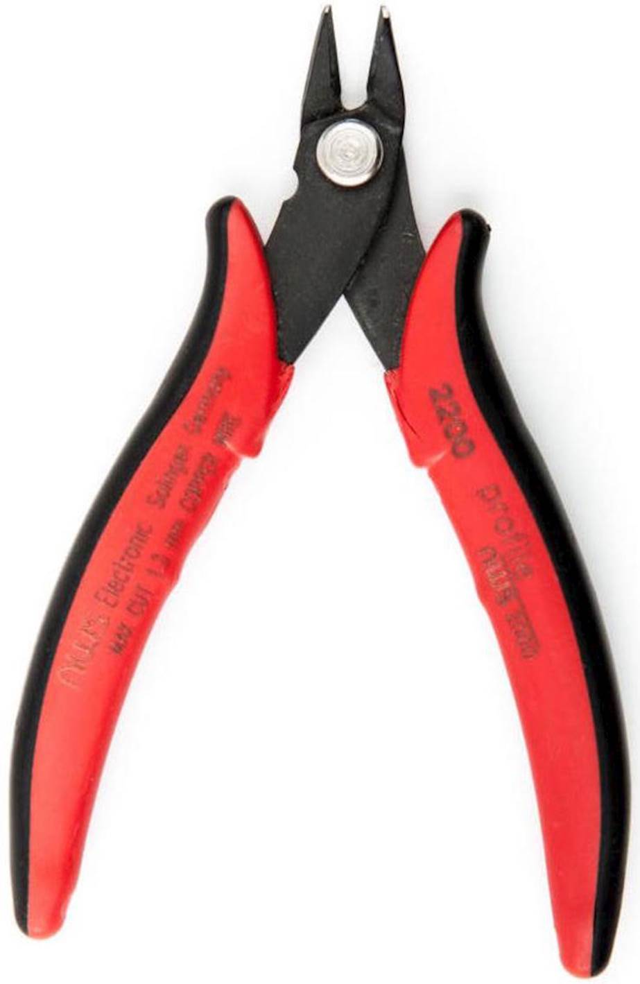
When working with breadboards and through-hole parts, you often have to shorten wires. Sometimes you have to cut plain wires that you need to connect parts in your circuit. Other times you have to cut the wires of a component like a resistor to make it easier to handle.
For these purposes, a wire cutter is indispensable.
Using a wire cutter is like using a pair of scissors. The only difference is that you usually cut different types of material. When cutting metal wires you should always wear safety glasses. Often, when I cut wires, the part I cut off flies right into my safety glasses.
Learning How to Solder
You can build nearly all of the book’s projects by plugging parts into a breadboard or directly into the Arduino board. But sooner or later you’ll have to learn how to solder if you want to become an expert in electronics. That’s mainly because you’ll learn the most by building projects, and even the simplest kits require some sort of soldering.
Many people think that soldering is difficult or requires expensive equipment, so they never try to do it. The truth is that it’s cheap and pretty easy. It requires some practice, but after only a few solder joints you’ll see that it’s not rocket science.
In this book, we have one project that requires you to solder a pin header to an ADXL335 breakout board. We need it for building the motion-sensing game controller in Chapter 6, Building a Motion-Sensing Game Controller. In this section, you’ll learn how to do it, and you’ll need the following equipment:
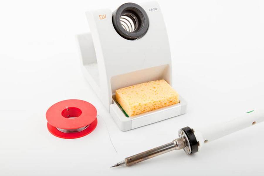
· A 25–30W soldering iron with a tip (preferably 1/16-inch) and a soldering stand.
· A standard 60/40 solder (rosin-core) spool for electronics work. It should have a 0.031-inch diameter.
· A sponge.
Before you start to solder, prepare your work area. Make sure you can easily access all your tools and that you have something to protect your work area from drops of solder. Wearing safety glasses is always a good idea! Even seemingly simple and harmless activities such as cutting wires can be very dangerous! Also make sure that your room has good ventilation, because the solder fumes aren’t good for your health.
Bring all parts into the correct position: attach the pin header to the breakout board, and make sure you can’t accidentally move it while soldering.
People get very creative when it comes to locking parts into a certain position. But you have to be careful—don’t use flammable materials to bring parts together. You also shouldn’t use parts that distribute heat very well, especially if they’re in touch with other parts. Duct tape might work in some cases, but be careful with it, too.
Try to find a piece of wood or something similar that has the right height: the height of the pin headers. Then you can put the breakout board on top of it and attach the pin headers. If you’re planning to solder more often and build some electronics projects, you should always look for these little tools that make your life easier.
In the following figure, you can see how I’ve prepared all parts:
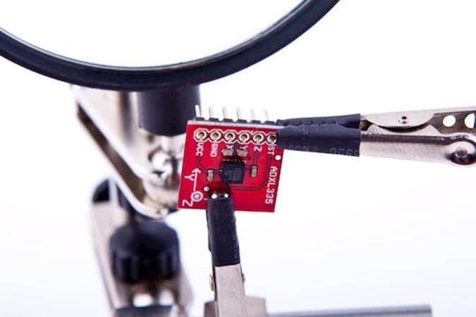
I’ve used a helping hand, a useful tool for locking parts into a position. Helping hands usually come with a magnifying glass, and they are cheap. If you plan to solder often, you should get one—they justify their name.

After you’ve prepared everything, it’s time to heat up the soldering iron. The main purpose of soldering is to join metallic surfaces. In our case, we’d like to join the surface of the pin header with the metal in the breakout board. To achieve this, we’ll heat up the metallic parts and then connect them using molten solder.
This process depends on a certain temperature, and having the wrong temperature is one of the most common soldering problems. If the temperature is too low, your solder joints might become fragile, and you also might have to touch the parts for too long, so you are liable to damage them. An extremely high temperature can damage your parts right away. Experts can debate for hours about “the right temperature,” but 600℉ to 650℉ (315℃ to 350℃) is a good compromise. Even with cheap soldering irons, you can adjust the temperature.
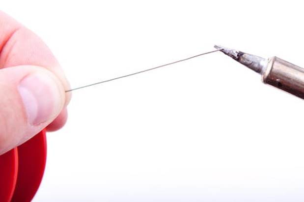
Dampen the sponge (it shouldn’t be too wet) and clean the tip by wiping it over the sponge a few times. Then tin the tip by putting a small amount of solder back onto it. This helps protect the tip, and it also improves the heat transfer to components:
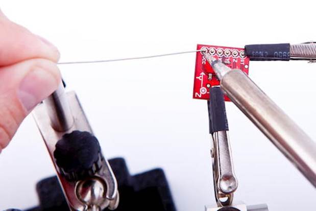
Soldering is mainly about heat distribution, and now it’s time to heat the joint. Make sure the tip of the soldering iron touches the part (pin header) and the pad of the breakout board at the same time:
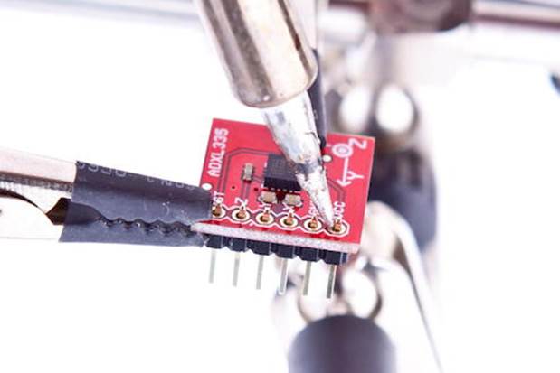
Keep it there for about a second, and then feed a small amount of solder between the tip and the pin:
As soon as the solder starts to flow, you’re safer, because the solder distributes heat automatically. Feed some more solder (not too much!) until you have a nice, shiny solder joint. The whole process shouldn’t take more than two to three seconds. When you’re finished, remove the iron tip quickly and give the joint a few seconds to cool down.
Repeat this for all six pin headers, and the result should look like this:
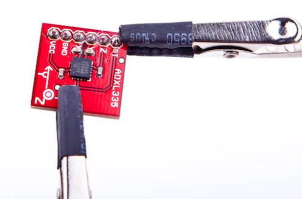
Test it by building the motion-sensing game controller, and play a video game to relax.
Congratulations! You have just finished your first soldering job!
Learning How to Desolder
Let’s face it: even if soldering isn’t that difficult, things can still go wrong. Sometimes you solder a part to the wrong place. In other cases you accidentally use too much solder and create unwanted connections. To correct such mistakes, you have to remove the excessive solder.
The following figure shows two of the most popular tools for desoldering. On the left you see a desoldering braid, and on the right you see a desoldering pump (also known as a solder sucker).
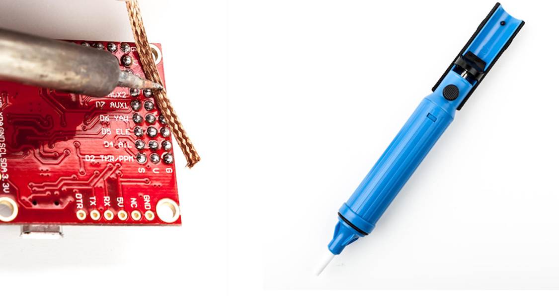
Both tools work the same in principle: you heat the solder you want to get rid of with the soldering iron, and then you use the tool to remove the molten solder. When you use the desoldering pump, you heat the solder until it melts, and then you press the pump’s button to suck the solder.
To desolder using braid, put the braid on top of the solder joint you’d like to remove. Then press the soldering iron’s tip to the braid and wait until the solder melts. The braid will suck the molten solder automatically.
Make sure that the distance between your fingers and the solder joint is reasonable, because the braid gets pretty hot. Also make sure you’re using a part of the braid that isn’t full of solder already.
This tutorial is only a starting point for your new shiny soldering career. You now know that soldering isn’t too difficult, and as a next step, you can try to build some beginner’s kits. All electronics stores offer them, and they usually come with soldering instructions, too. You can also find excellent tutorials and even videos on the Internet to build your skills.[143]
Footnotes
|
[141] |
Lightbulb image is from Benji Park at https://openclipart.org/detail/26218/Lightbulb_Bright-by-bpcomp. |
|
[142] |
http://www.digikey.de/en/resources/conversion-calculators/conversion-calculator-resistor-color-code-4-band |
|
[143] |
http://store.curiousinventor.com/guides/How_to_Solder |
All materials on the site are licensed Creative Commons Attribution-Sharealike 3.0 Unported CC BY-SA 3.0 & GNU Free Documentation License (GFDL)
If you are the copyright holder of any material contained on our site and intend to remove it, please contact our site administrator for approval.
© 2016-2026 All site design rights belong to S.Y.A.