Arduino: A Quick-Start Guide, Second Edition (2015)
Part I. Getting Started with Arduino
Chapter 1. Welcome to the Arduino
The Arduino was originally built for designers and artists—people with little technical expertise. Even if they didn’t have programming experience, the Arduino enabled them to create sophisticated design prototypes and some amazing interactive artwork. So, it should come as no surprise that the first steps with the Arduino are very easy, even more so for people with a strong technical background.
But it’s still important to get the basics right. You’ll get the most out of working with the Arduino if you familiarize yourself with the Arduino board itself, with its development environment, and with techniques such as serial communication.
One thing to understand before getting started is physical computing. If you have worked with computers before, you might wonder what this means. After all, computers are physical objects, and they accept input from physical keyboards and mice. They output sound and video to physical speakers and displays. So, isn’t all computing physical computing in the end?
In principle, regular computing is a subset of physical computing: keyboard and mouse are sensors for real-world inputs, and displays or printers are actuators. But controlling special sensors and actuators using a regular computer is very difficult. Using an Arduino, it’s a piece of cake to control sophisticated and sometimes even weird devices. In the rest of this book, you’ll learn how, and in this chapter you’ll get started with physical computing by learning how to control the Arduino, what tools you need, and how to install and configure them. Then we’ll quickly get to the fun part: you’ll develop your first program for the Arduino.
What You Need
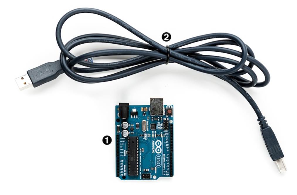
1. An Arduino board, such as the Uno, Duemilanove, or Diecimila.
2. A USB cable to connect the Arduino to your computer.
3. The Arduino IDE (see Installing the Arduino IDE). You will need it in every chapter, so after this chapter I’ll no longer mention it explicitly.
You’ll find photos such as this in most of the following chapters. The numbers in the photo correspond to the numbers in the parts list. In later chapters the photos do not show standard parts, such as the Arduino board or a USB cable.
What Exactly Is an Arduino?
Beginners often get confused when they discover the Arduino project. When looking for the Arduino, they hear and read strange names such as Uno, Duemilanove, Diecimila, LilyPad, or Seeeduino. The problem is that there is no such thing as “the Arduino.”
A couple of years ago, the Arduino team designed a microcontroller board and released it under an open-source license. You could buy fully assembled boards in a few electronics shops, but people interested in electronics could also download its schematic[20] and build it themselves.
Over the years, the Arduino team improved the board’s design and released several new versions. They usually had Italian names, such as Uno, Duemilanove, or Diecimila; you can find online a list of all boards ever created by the Arduino team.[21]
Here’s a small selection of Arduinos. They may differ in their appearance, but they have a lot in common, and you can program them all with the same tools and libraries.
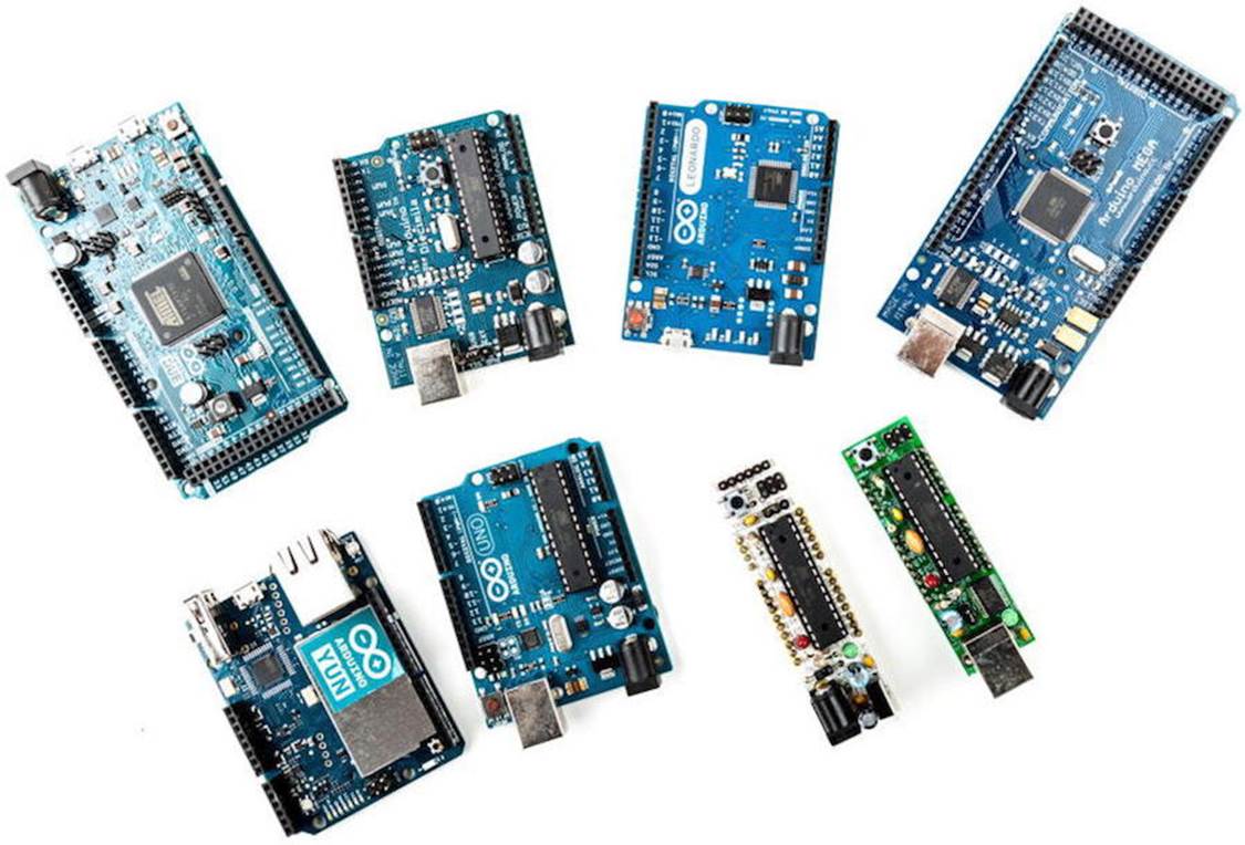
Although they’re the same in principle, they differ in some details. The Arduino Due[22] has many more IO pins than most of the other Arduinos and uses a powerful 32-bit ARM core microcontroller, while the Arduino Nano[23] was designed to be used on a breadboard, so it doesn’t have any sockets. From my experience, beginners should start with one of the “standard” boards—that is, with an Uno, for example.
The Arduino team didn’t only constantly improve the hardware design, they also invented new designs for special purposes. For example, they created the Arduino LilyPad[24] to embed a microcontroller board into textiles. You can use it to build interactive T-shirts.
In addition to the official boards, you can find countless Arduino clones on the Web. Everybody is allowed to use and change the original board design, and many people created their very own version of Arduino-compatible boards. Among many others, you can find the Freeduino, Seeeduino, Boarduino, and the amazing Paperduino,[25] an Arduino clone without a printed circuit board. All of its parts are attached to an ordinary piece of paper.
Arduino is a registered trademark—only the official boards are named “Arduino”—so clones usually have names ending with “duino.” You can use every clone that is fully compatible with the original Arduino to build all of the book’s projects.
Exploring the Arduino Board
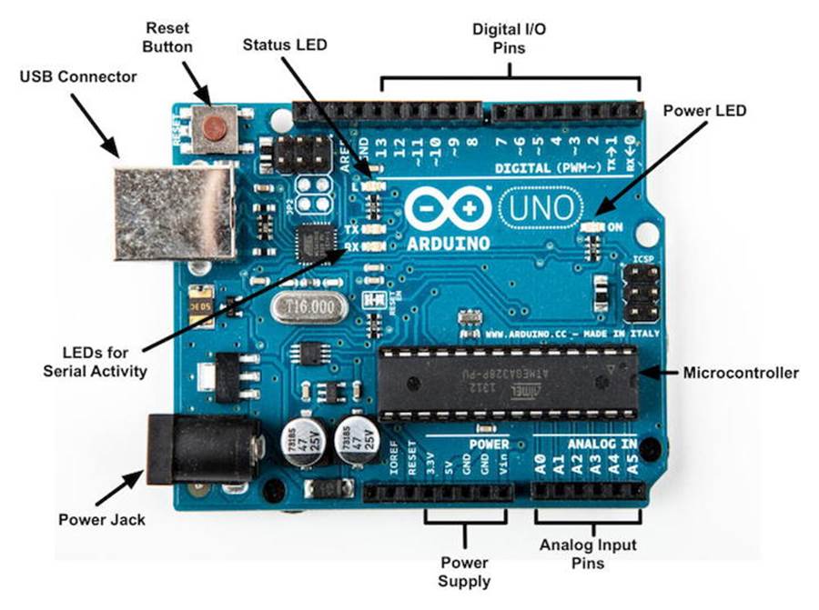
The photo shows an Arduino Uno board and its most important parts. I’ll explain them one by one. Let’s start with the USB connector. To connect an Arduino to your computer, you just need a USB cable. The type of the USB cable depends on the type of Arduino board you’re using. The Arduino Uno comes with the big standard-B plug, while other boards, such as the Arduino Leonardo or the Arduino Due, have the small micro-B plugs.
You can use the USB connection for various purposes:
· Upload new software to the board. (You’ll see how to do this in Compiling and Uploading Programs.)
· Communicate with the Arduino board and your computer. (You’ll learn that in Using Serial Ports.)
· Supply the Arduino board with power.
As an electronic device, the Arduino needs power. One way to power it is to connect it to a computer’s USB port, but that isn’t a good solution in some cases. Some projects don’t necessarily need a computer, and it would be overkill to use a whole computer just to power the Arduino. Also, the USB port delivers only 5 volts, and sometimes you need more.
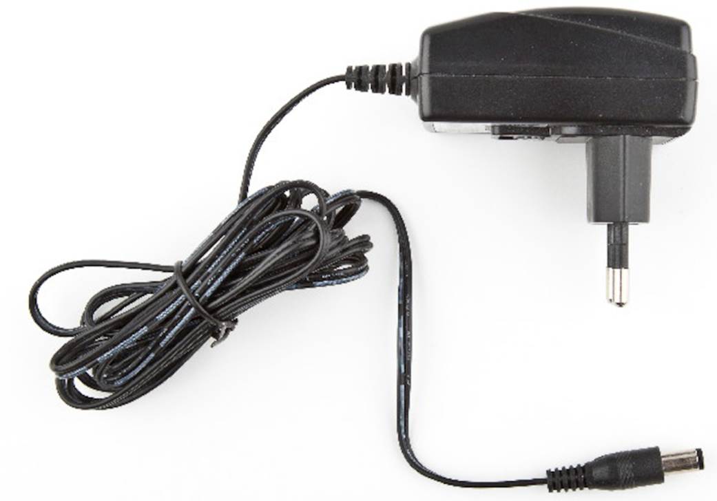
Figure 1. A typical AC adapter.
In these situations, the best solution usually is an AC adapter supplying 9 volts. (The recommended range is 7V to 12V.)[26] You need an adapter with a 2.1mm barrel tip and a positive center. (You don’t need to understand what that means; just ask for it in your local electronics store.) Plug it into the Arduino’s power jack, and it will start immediately, even if it isn’t connected to a computer. By the way, even if you connect the Arduino to a USB port, it will use the external power supply if available.
Please note that older versions of the Arduino board (Arduino NG and Diecimila) don’t switch automatically between an external power supply and a USB supply. They come with a power selection jumper labeled PWR_SEL, and you manually have to set it to EXT or USB, respectively. (See Figure 2, Older Arduinos have a power source selection jumper.)
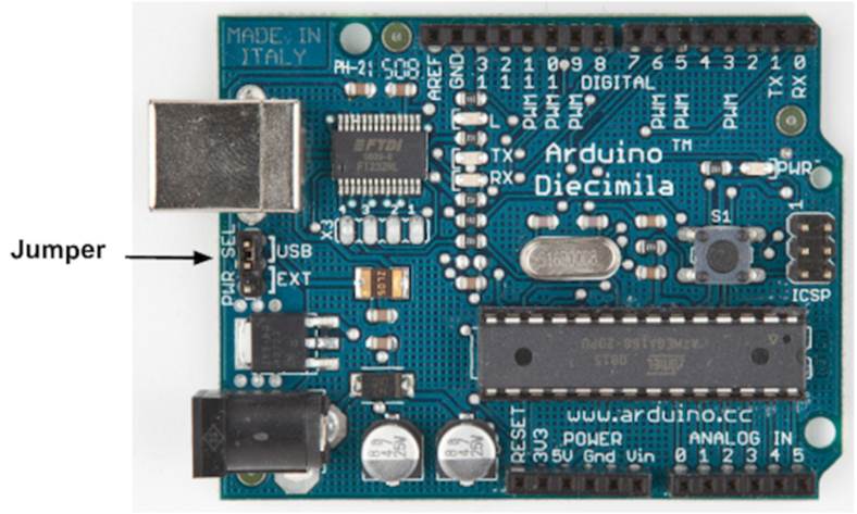
Figure 2. Older Arduinos have a power source selection jumper.
Now you know two ways to supply the Arduino with power. But the Arduino isn’t greedy and happily shares its power with other devices. At the bottom of the board shown in Exploring the Arduino Board, you can see several sockets (sometimes I’ll also call them pins, because internally they are connected to pins in the microcontroller) related to power supply:
· Using the pins labeled 3V3 and 5V, you can power external devices connected to the Arduino with 3.3 volts or 5 volts.
· Two ground pins labeled GND allow your external devices to share a common ground with the Arduino.
· Some projects need to be portable, so they’ll use a portable power supply, such as batteries. You connect an external power source, such as a battery pack, to the Vin and GND sockets.
If you connect an AC adapter to the Arduino’s power jack, you can access the adapter’s voltage through the Vin pin.
On the lower right of the board, you see six analog input pins named A0–A5. You can use them to connect analog sensors to the Arduino. They take sensor data and convert it into a number between 0 and 1023. In Chapter 5, Sensing the World Around Us, we’ll use them to connect a temperature sensor to the Arduino.
At the board’s top are 14 digital IO pins named D0–D13. Depending on your needs, you can use these pins for both digital input and digital output, so you can read the state of a pushbutton or switch to turn on and off an LED. (We’ll do this in Working with Buttons.) Six of them (D3, D5, D6, D9, D10, and D11) can also act as analog output pins. In this mode, they convert values from 0 to 255 into analog voltages.
Analog and Digital Signals
Nearly all physical processes are analog. Whenever you observe a natural phenomenon, such as electricity or sound, you’re actually receiving an analog signal. One of the most important properties of these analog signals is that they are continuous. For every given point in time, you can measure the strength of the signal, and in principle you could register even the tiniest variation of the signal.
But although we live in an analog world, we are also living in the digital age. When the first computers were built a few decades ago, people quickly realized that it’s much easier to work with real-world information when it’s represented as numbers and not as an analog signal, such as voltage or volume. For example, it’s much easier to manipulate sounds using a computer when the sound waves are stored as a sequence of numbers. Every number in this sequence could represent the signal’s loudness at a certain point in time.
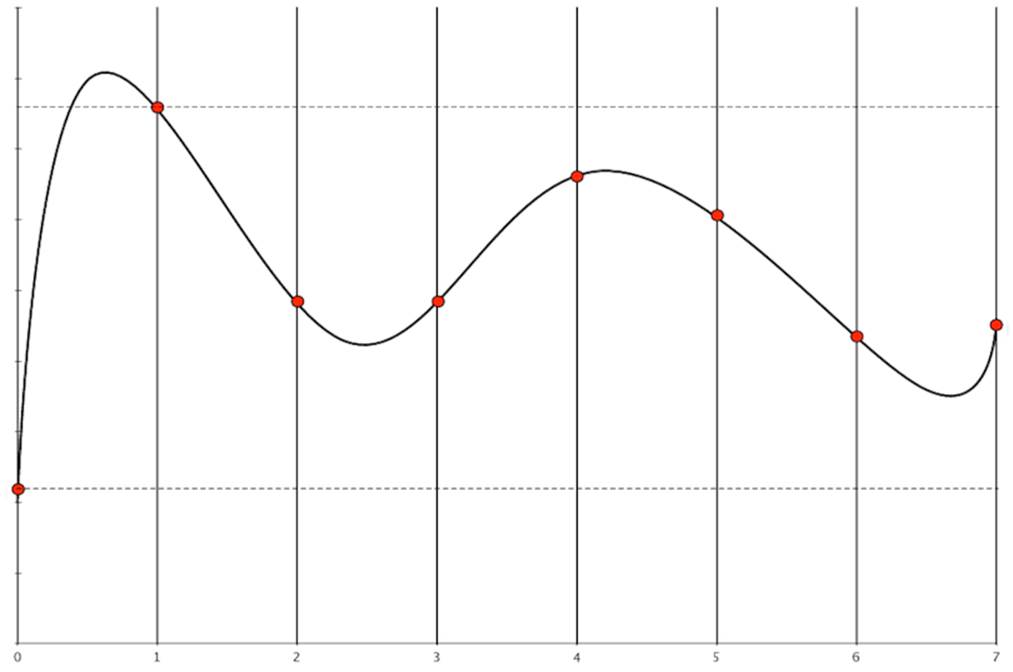
So instead of storing the complete analog signal (as is done on records), we measure the signal only at certain points in time (see the following figure). We call this process sampling, and the values we store are called samples. The frequency we use to determine new samples is called the sampling rate. For an audio CD, the sampling rate is 44.1 kHz: we gather 44,100 samples per second.
We also have to limit the samples to a certain range. On an audio CD, every sample uses 16 bits. In the following figure, the range is denoted by two dashed lines, and we had to cut off a peak at the beginning of the signal.
Although you can connect both analog and digital devices to the Arduino, you usually don’t have to think much about it. The Arduino automatically performs the conversion from analog to digital for you.
All of these pins are connected to a microcontroller, which combines a CPU with some peripheral functions, such as IO channels. Many different types of microcontrollers are available, but the majority of Arduinos usually come with an ATmega328, an 8-bit microcontroller produced by a company named Atmel. Still there are Arduino models—for example, the Arduino Mega or the Arduino Due—that use more powerful microcontrollers.
Although modern computers load programs from a hard drive, microcontrollers usually have to be programmed. That means you have to load your software into the microcontroller via a cable, and once the program has been uploaded, it stays in the microcontroller until it gets overwritten with a new program. Whenever you supply power to the Arduino, the program currently stored in its microcontroller gets executed automatically. Sometimes you want the Arduino to start right from the beginning. With the reset button on the right side of the board, you can do that. If you press it, everything gets reinitialized, and the program stored in the microcontroller starts again. (We’ll use it in First Version of a Binary Die.)
On most Arduino boards you’ll also find a couple of LEDs. You’ll learn more about them in Hello, World!.
Installing the Arduino IDE
To make it as easy as possible to get started with the Arduino, the developers have created a simple but useful integrated development environment (IDE). It runs on many different operating systems. Before you can create your first projects, you have to install it.
Important note: at the time of this writing, two different versions of the IDE are available (1.0.6 and 1.6.0).[27] Chances are good that the 1.0.x branch of the Arduino IDE will no longer be maintained in the future. So, you should use 1.6.x where possible and use 1.0.x only if you need to use libraries that don’t work on 1.6.x yet. The following instructions refer to the 1.6.0 version.
Installing the Arduino IDE on Windows
The Arduino IDE runs on all the latest versions of Microsoft Windows, such as Windows 8.1 and Windows 7. The software comes in two flavors: as a Windows installer or as a self-contained zip archive. Check the Arduino’s download page[28] for the latest version of either one.
If you have administrative privileges on your machine, use the installer because it installs not only the IDE, but also all the drivers you need. In this case you usually don’t need anything else and can use the IDE right away.
If you don’t have administrative privileges, download the zip archive and extract it to a location of your choice. Before you first start the IDE, you must install drivers for the Arduino’s USB port. This process depends on the Arduino board you’re using and on your flavor of Windows.
Installing the Drivers for Current Arduino Boards
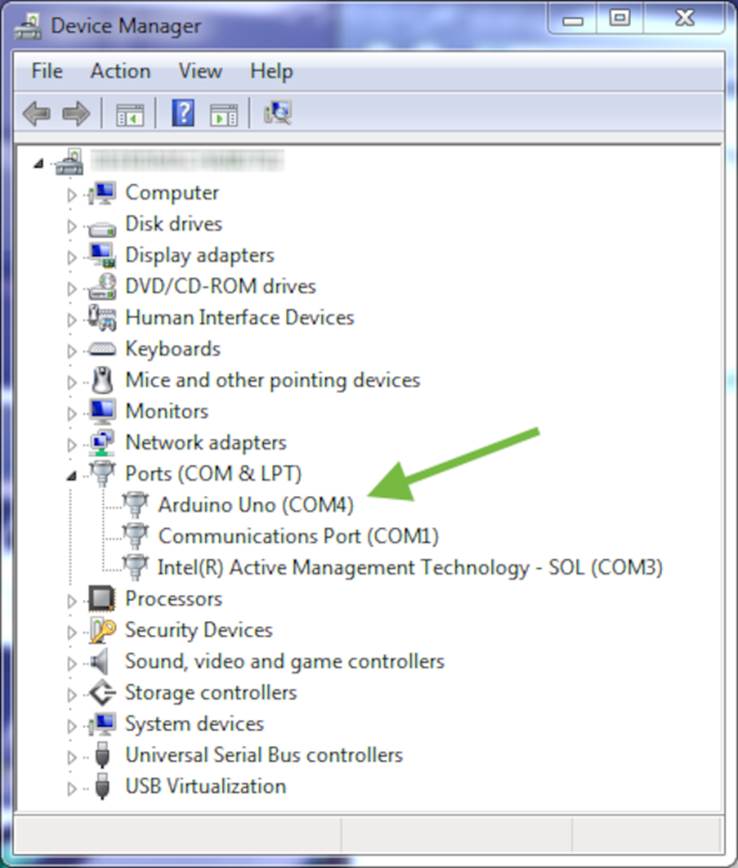
To install drivers for recent boards, such as the Arduino Uno, plug the Arduino into a USB port first to start the automatic driver installation process. This process will likely fail, and you’ll have to open the system Control Panel and start the Device Manager. (You can find it under System and Security.)[29] In the Ports (COM & LPT) section, you’ll probably find an entry named Arduino Uno (COMxx).
If you can’t find that entry, search for Unknown Device in the Other Devices menu—Figure 3, Sometimes the Arduino isn't recognized.
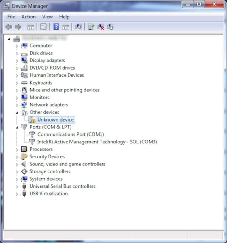
Figure 3. Sometimes the Arduino isn’t recognized.
Right-click the entry belonging to the Arduino board and choose Update Driver Software. Select the Browse My Computer for Driver Software option. Go to the drivers folder of the archive you’ve extracted and select the arduino.inf file. (See Figure 4, The content of the drivers folder.) In older versions of the IDE the file was named Arduino Uno.inf.
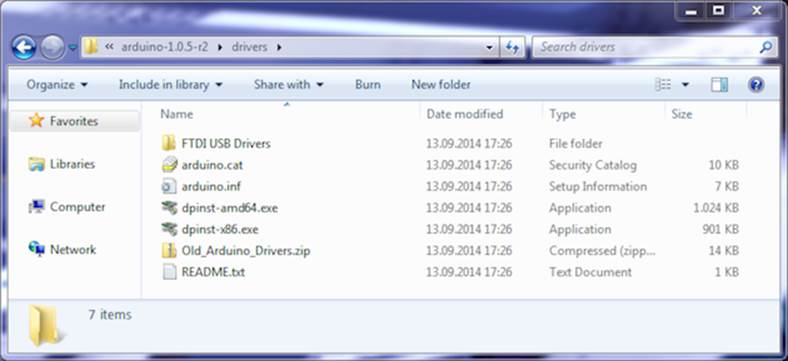
Figure 4. The content of the drivers folder
After you’ve installed the driver, you can start the Arduino IDE and work with the board. (If you’re running Windows 8.x, you have to disable some protection mechanisms before you install the driver.)[30]
Installing the Drivers for Older Arduino Boards
Driver installation for older boards like the Duemilanove, Diecimila, or Nano is a bit different. Still, you have to plug in the board first.
On Windows Vista, driver installation usually happens automatically. Lean back and watch the hardware wizard’s messages pass by until it says you can use the newly installed USB hardware.
Windows 8.x, Windows 7, and Windows XP may not find the drivers on Microsoft’s update sites automatically. Sooner or later, the hardware wizard asks you for the path to the right drivers after you have told it to skip automatic driver installation from the Internet. Depending on your Arduino board, you have to point it to the right location in the Arduino installation directory—that is the drivers/FTDI USB Drivers directory.
After the drivers have been installed, you can start the Arduino executable from the archive’s main directory by double-clicking it.
Please note that the USB drivers don’t change as often as the Arduino IDE. Whenever you install a new version of the IDE, check whether you have to install new drivers, too. Usually it isn’t necessary.
Installing the Arduino IDE on Mac OS X
The Arduino IDE is available as a zip file for Mac OS X.[31] The IDE depends on the Java Virtual Machine, and at the time of this writing it’s available for Java 6 (recommended) and Java 7 (experimental). Download it, double-click it, and drag the Arduino icon to your Applications folder. If you hadn’t installed Java already, Mac OS X will ask you for permission to install it.
If you’re using an Arduino Uno or an Arduino Mega 2560, you are done and can start the IDE. Before you can use the IDE with an older Arduino, such as the Duemilanove, Diecimila, or Nano, you have to install drivers for the Arduino’s serial port. You can find the latest version online.[32]Download the package for your platform (it usually has a name such as FTDIUSBSerialDriver_10_4_10_5_10_6.mpkg), double-click it, and follow the installation instructions on the screen.
When installing a new version of the Arduino IDE, you usually don’t have to install the drivers again (only when more recent drivers are available).
Installing the Arduino IDE on Linux
Installation procedures on Linux distributions are still not very homogeneous. The Arduino IDE works fine on nearly all modern Linux versions, but the installation process differs from distribution to distribution. Also, you often have to install additional software (the Java Virtual Machine, for example) that comes preinstalled with other operating systems.
It’s best to check the official documentation[33] and look up the instructions for your preferred system.
Now that the drivers and IDE are installed, let’s see what it has to offer.
Meeting the Arduino IDE
Compared to IDEs such as Eclipse, Xcode, or Microsoft Visual Studio, the Arduino IDE is simple. It mainly consists of an editor, a compiler, a loader, and a serial monitor. (See Figure 5, The Arduino IDE is well organized or, even better, start the IDE on your computer.)
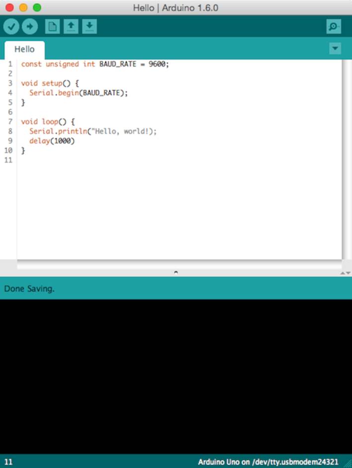
Figure 5. The Arduino IDE is well organized.
It has no advanced features such as a debugger or code completion. You can change only a few preferences, and as a Java application it does not fully integrate into the Mac desktop. It’s still usable, though, and even has decent support for project management.
The image that follows shows the IDE’s toolbar, which gives you instant access to the functions you’ll need most:
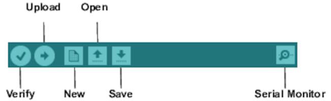
· With the Verify button, you can compile the program that’s currently in the editor. So, in some respects, “Verify” is a misnomer, because clicking the button doesn’t only verify the program syntactically, it also turns the program into a representation suitable for the Arduino board. You can invoke this function using the ⌘R keyboard shortcut on a Mac or Ctrl-R on all other systems.
· When you click the Upload button (⌘U or Ctrl-U), the IDE compiles the current program and uploads it to the Arduino board you’ve chosen in the IDE’s Tools > Serial Port menu. (You’ll learn more about this in Compiling and Uploading Programs.)
· The New button (⌘N or Ctrl-N) creates a new program by emptying the content of the current editor window. Before that happens, the IDE gives you the opportunity to store all unsaved changes.
· Open (⌘O or Ctrl-O) opens an existing program from the file system.
· Save (⌘S or Ctrl-S) saves the current program.
· The Arduino can communicate with a computer via a serial connection. Clicking the Serial Monitor button (⇧⌘M or Ctrl-Shift-M) opens a serial monitor window that allows you to watch the data sent by an Arduino and also to send data back.
Although using the IDE is easy, you might run into problems or want to look up something special. In such cases, take a look at the Help menu. It points to many useful resources at the Arduino’s website that provide not only quick solutions to all typical problems, but also reference materials and tutorials.
Hello, World!
To get familiar with the IDE’s most important features, we’ll create a simple program that makes an light-emitting diode (LED) blink. An LED is a cheap and efficient light source, and the Arduino already comes with several LEDs. One LED shows whether the Arduino is currently powered, and two other LEDs blink when data is transmitted or received via a serial connection.
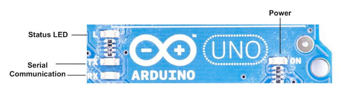
In our first little project, we’ll make the Arduino’s status LED blink. The status LED is connected to digital IO pin 13. Digital pins act as a kind of switch and can be in one of two states: HIGH or LOW. If set to HIGH, the output pin is set to 5 volts, causing a current to flow through the LED so it lights up. If set back to LOW, the current flow stops, and the LED turns off. You don’t need to know exactly how electricity works at the moment, but if you’re curious, take a look at Current, Voltage, and Resistance.
Open the IDE and enter the following code in the editor:
|
Welcome/HelloWorld/HelloWorld.ino |
|
|
Line 1 |
const unsigned int LED_PIN = 13; |
|
- |
const unsigned int PAUSE = 500; |
|
- |
|
|
- |
void setup() { |
|
5 |
pinMode(LED_PIN, OUTPUT); |
|
- |
} |
|
- |
|
|
- |
void loop() { |
|
- |
digitalWrite(LED_PIN, HIGH); |
|
10 |
delay(PAUSE); |
|
- |
digitalWrite(LED_PIN, LOW); |
|
- |
delay(PAUSE); |
|
- |
} |
Let’s see how this works and dissect the program’s source code piece by piece. In the first two lines, we define two unsigned int constants using the const keyword. LED_PIN refers to the number of the digital IO pin we’re using, and PAUSE defines the length of the blink period in milliseconds.
Every Arduino program needs a function named setup, and ours starts in line 4. A function definition always adheres to the following scheme:
|
|
<return value type> <function name> '(' <list of parameters> ')' |
In our case the function’s name is setup, and its return value type is void: it returns nothing. setup doesn’t expect any arguments, so we left the parameter list empty. Before we continue with the dissection of our program, you should learn more about the Arduino’s data types.
Arduino Data Types
Every piece of data you store in an Arduino program needs a type. Depending on your needs, you can choose from the following:
· boolean values take up one byte of memory and can be true or false.
· char variables take up one byte of memory and store numbers from -128 to 127. These numbers usually represent characters encoded in ASCII; that is, in the following example, c1 and c2 have the same value:
|
|
char c1 = 'A'; |
|
|
char c2 = 65; |
· Note that you have to use single quotes for char literals.
· byte variables use one byte and store values from 0 to 255.
· An int variable needs two bytes of memory; you can use it to store numbers from -32,768 to 32,767. Its unsigned equivalent unsigned int also consumes two bytes of memory but stores numbers from 0 to 65,535.
· For bigger numbers, use long. It consumes four bytes of memory and stores values from -2,147,483,648 to 2,147,483,647. The unsigned variant unsigned long also needs four bytes but ranges from 0 to 4,294,967,295.
· float and double are the same at the moment on most Arduino boards, and you can use these types for storing floating-point numbers. Both use four bytes of memory and are able to store values from -3.4028235E+38 to 3.4028235E+38. On the Arduino Due, double values are more accurate and occupy eight bytes of memory.
· You need void only for function declarations. It denotes that a function doesn’t return a value.
· Arrays store collections of values having the same type:
|
|
int values[2]; // A two-element array |
|
|
values[0] = 42; // Set the first element |
|
|
values[1] = -42; // Set the second element |
|
|
int more_values[] = { 42, -42 }; |
|
|
int first = more_values[0]; // first == 42 |
· In the preceding example, the arrays values and more_values contain the same elements. We have used only two different ways of initializing an array. Note that the array index starts at 0, and keep in mind that uninitialized array elements contain unreliable values.
· A string is an array of char values. The Arduino environment supports the creation of strings with some syntactic sugar—all these declarations create strings with the same contents.
|
|
char string1[8] = { 'A', 'r', 'd', 'u', 'i', 'n', 'o', '\0' }; |
|
|
char string2[] = "Arduino"; |
|
|
char string3[8] = "Arduino"; |
|
|
char string4[] = { 65, 114, 100, 117, 105, 110, 111, 0 }; |
· Strings should always be terminated by a zero byte. When you use double quotes to create a string, the zero byte will be added automatically. That’s why you have to add one byte to the size of the corresponding array.
In Emailing Directly from an Arduino, you’ll learn how to use the Arduino’s String class. It makes working with strings safer and more convenient.
Arduino Functions
Arduino calls setup once when it boots, and we use it in our “HelloWorld” example in Hello, World!, for initializing the Arduino board and all the hardware we have connected to it. We use the pinMode method to turn pin 13 into an output pin. This ensures the pin can provide enough current to light up an LED. The default state of a pin is INPUT, and both INPUT and OUTPUT are predefined constants.[34]
Another mandatory function named loop begins in line 8. It contains the main logic of a program, and the Arduino calls it in an infinite loop. Our program’s main logic has to turn on the LED connected to pin 13 first. To do this, we use digitalWrite and pass it the number of our pin and the constant HIGH. This means the pin will output 5 volts until further notice, and the LED connected to the pin will light up.
The program then calls delay and waits for 500 milliseconds doing nothing. During this pause, pin 13 remains in HIGH state, and the LED continues to burn. The LED is eventually turned off when we set the pin’s state back to LOW using digitalWrite again. We wait another 500 milliseconds, and then the loop function ends. The Arduino starts it again, and the LED blinks.
In the next section, you’ll learn how to bring the program to life and transfer it to the Arduino.
Compiling and Uploading Programs
Before you compile and upload a program to the Arduino, you have to configure two things in the IDE: the type of Arduino you’re using and the serial port your Arduino is connected to. Since Arduino 1.6.0, the IDE tries to identify all Arduino boards that are connected to your computer automatically. This feature works quite well, but it also fails sometimes. So, you need to learn how to determine the type of your Arduino board and the name of the serial port it is connected to.
Identifying the Arduino type is easy, because it is printed on the board. Popular types are Uno, Duemilanove, Diecimila, Nano, Mega, Mini, NG, BT, LilyPad, Pro, or Pro Mini. In some cases, you also have to check what microcontroller your Arduino uses—most have an ATmega328. You can find the microcontroller type printed on the microcontroller itself. When you have identified the exact type of your Arduino, choose it from the Tools > Board menu.
Now you have to choose the serial port your Arduino is connected to from the Tools > Serial Port menu. On Mac OS X, the name of the serial port usually starts with /dev/tty.usbserial or /dev/tty.usbmodem. (On my MacBook Pro, it’s /dev/tty.usbmodem24321.) On Linux systems, it should be /dev/ttyUSB0, /dev/ttyUSB1, or something similar, depending on the number of USB ports your computer has.
On Windows systems, you have to use the Device Manager to find out the right serial port. In the Device Manager, look for USB Serial Port below the Ports (COM & LPT) menu entry. (See Installing the Drivers for Current Arduino Boards) Usually the port is named COM1, COM2, or something similar.
After you have chosen the right serial port, click the Verify button, and you should see the following output in the IDE’s message area (the Arduino IDE calls programs sketches):
|
|
Build options changed, rebuilding all |
|
|
|
|
|
Sketch uses 1,030 bytes (3%) of program storage space. Maximum is 32,256 bytes. |
|
|
Global variables use 9 bytes (0%) of dynamic memory, leaving 2,039 bytes for |
|
|
local variables. Maximum is 2,048 bytes. |
This means the IDE has successfully compiled the source code into 1,030 bytes of machine code that we can upload to the Arduino. If you see an error message instead, check whether you have typed in the program correctly. (When in doubt, download the code from the book’s website.)[35]Depending on the Arduino board you’re using, the byte maximum may differ. On an Arduino Duemilanove, it’s usually 14336, for example. Also, the size of the sketch might be slightly different depending on the version of the Arduino IDE.
Now click the Upload button, and after a few seconds, you should see the following output in the message area:
|
|
Sketch uses 1,030 bytes (3%) of program storage space. Maximum is 32,256 bytes. |
|
|
Global variables use 9 bytes (0%) of dynamic memory, leaving 2,039 bytes for |
|
|
local variables. Maximum is 2,048 bytes. |
This is exactly the same message we got after compiling the program, and it tells us that the 1,030 bytes of machine code were transferred successfully to the Arduino. In case of any errors, check whether you have selected the correct Arduino type and the correct serial port in the Tools menu.
During the upload process, the TX and RX LEDs will flicker for a few seconds. This is normal, and it happens whenever the Arduino and your computer communicate via the serial port. When the Arduino sends information, it turns on the TX LED. When it gets some bits, it turns on the RX LED. Because the communication is pretty fast, the LEDs start to flicker, and you cannot identify the transmission of a single byte. (If you can, you’re probably an alien.)
As soon as the code has been transmitted completely, the Arduino executes it. In our case, this means the status LED starts to blink. It turns on for half a second, then it turns off for half a second, and so on.
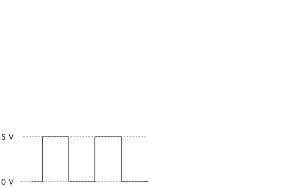
The figure shows the activity on pin 13 while the program is running.
The pin starts in LOW state and doesn’t output any current. We use digitalWrite to set it to HIGH and let it output 5 volts for 500 milliseconds. Finally, we set it back to LOW for 500 milliseconds and repeat the whole process.
That’s it! You’ve created your first physical computing project. You’ve written some code, and it makes the world brighter. Your very own digital version of “fiat lux.”[36]
Admittedly, the status LED doesn’t look spectacular. In Chapter 3, Building Binary Dice, we’ll attach “real” LEDs to the Arduino.
You’ll need the theory and skills you’ve learned in this chapter for nearly every Arduino project. In the next chapter, you’ll see how to gain more control over LEDs, and you’ll learn how to benefit from more advanced features of the Arduino IDE.
What If It Doesn’t Work?
Choosing the wrong serial port or Arduino type is the most common mistake when doing the first experiments with an Arduino. If you get an error message such as “Serial port already in use” when uploading a sketch, check whether you have chosen the right serial port from the Tools > Serial Port menu. If you get messages such as “Problem uploading to board” or “Programmer is not responding,” check whether you have chosen the right Arduino board from the Tools > Board menu.
Your Arduino programs, like all programs, will contain bugs. The compiler will detect typos and syntax errors. Figure 6, The Arduino IDE explains syntax errors nicely shows a typical error message. Instead of pinMode, we called pinMod, and because the compiler didn’t find a function with that name, it stopped with an error message. The Arduino IDE highlights the line, showing the error with a yellow background, and prints a helpful error message.
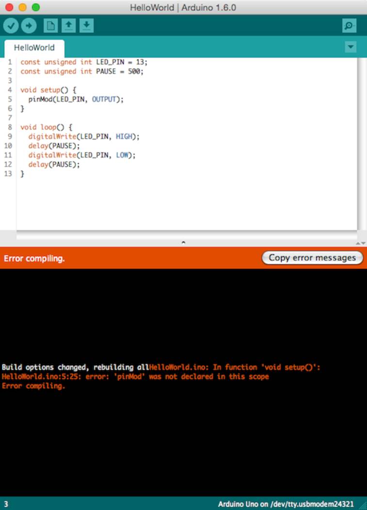
Figure 6. The Arduino IDE explains syntax errors nicely.
Other bugs might be more subtle, and sometimes you have to carefully study your code and use some plain old debugging techniques. (In Debug It! Find, Repair, and Prevent Bugs in Your Code [But09], you can find plenty of useful advice on this topic.)
Exercises
· Try different blink patterns using more pauses and vary the pause length. (They don’t necessarily all have to be the same.) Also, experiment with very short pauses that make the status LED blink at a high frequency. Can you explain the effect you’re observing?
· Let the status LED output your name in Morse code.[37]
Footnotes
|
[20] |
http://arduino.cc/en/uploads/Main/arduino-uno-schematic.pdf |
|
[21] |
See http://arduino.cc/en/Main/Boards and http://arduino.cc/en/Main/Products. |
|
[22] |
http://arduino.cc/en/Main/ArduinoBoardDue |
|
[23] |
http://arduino.cc/en/Main/ArduinoBoardNano |
|
[24] |
http://arduino.cc/en/Main/ArduinoBoardLilyPad |
|
[25] |
http://lab.guilhermemartins.net/2009/05/06/paperduino-prints/ |
|
[26] |
http://www.arduino.cc/playground/Learning/WhatAdapter |
|
[27] |
There’s even one more for the Arduino Galileo at https://communities.intel.com/docs/DOC-22226. |
|
[28] |
http://arduino.cc/en/Main/Software |
|
[29] |
http://windows.microsoft.com/en-us/windows/open-device-manager#1TC=windows-7 |
|
[30] |
https://learn.sparkfun.com/tutorials/installing-arduino-ide/windows |
|
[31] |
http://arduino.cc/en/Main/Software |
|
[32] |
http://www.ftdichip.com/Drivers/VCP.htm |
|
[33] |
http://www.arduino.cc/playground/Learning/Linux |
|
[34] |
See http://arduino.cc/en/Tutorial/DigitalPins for the official documentation. |
|
[35] |
http://www.pragprog.com/titles/msard2 |
|
[36] |
http://en.wikipedia.org/wiki/Fiat_lux |
|
[37] |
http://en.wikipedia.org/wiki/Morse_code |
All materials on the site are licensed Creative Commons Attribution-Sharealike 3.0 Unported CC BY-SA 3.0 & GNU Free Documentation License (GFDL)
If you are the copyright holder of any material contained on our site and intend to remove it, please contact our site administrator for approval.
© 2016-2026 All site design rights belong to S.Y.A.