Arduino: A Quick-Start Guide, Second Edition (2015)
Part II. Eleven Arduino Projects
Chapter 5. Sensing the World Around Us
Instead of communicating via mouse or keyboard as with regular computers, you need to connect special sensors to the Arduino so that it can sense changes around it. You can attach sensors that measure the current temperature, the acceleration, or the distance to the nearest object.
Sensors make up an important part of physical computing, and the Arduino makes using various sensor types a breeze. In this chapter, we will use both digital and analog sensors to capture some real-world state, and all we need is a couple of wires and some small programs.
We’ll take a close look at two sensor types: an ultrasonic sensor that measures distances and a temperature sensor that measures, well, temperatures. With the ultrasonic sensor, we’ll build a digital metering rule to help us measure distances remotely.
Although ultrasonic sensors deliver quite accurate results, we can still improve their precision with some easy tricks. Interestingly, the temperature sensor will help us with this, and at the end of the chapter, we will have created a fairly accurate digital distance meter. We’ll also build a nice graphical application that visualizes the data we get from the sensors.
But the Arduino doesn’t only make using sensors easy. It also encourages good design for both your circuits and your software. For example, although we end up using two sensors, they are completely independent. All the programs we develop in this chapter will run without changes on the final circuit.
What You Need
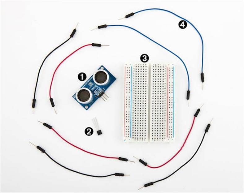
1. A Parallax PING))) sensor
2. A TMP36 temperature sensor from Analog Devices
3. A breadboard
4. Some wires
5. An Arduino board, such as the Uno, Duemilanove, or Diecimila
6. A USB cable to connect the Arduino to your computer
Measuring Distances with an Ultrasonic Sensor
Measuring distances automatically and continuously comes in handy in many situations. Think of a robot that autonomously tries to find its way or of an automatic burglar alarm that rings a bell or calls the police whenever someone is too near your house or the Mona Lisa. All this is possible with Arduino. But before you can create that burglar alarm or robot, you need to understand some key concepts.
Many different types of sensors for measuring distances are available, and the Arduino plays well with most of them. Some sensors use ultrasound, while others use infrared light or even laser. But in principle all sensors work the same way: they emit a signal, wait for the echo to return, and measure the time the whole process took. Because we know how fast sound and light travel through the air, we can then convert the measured time into a distance.
In our first project, we’ll build a device that measures the distance to the nearest object and outputs it on the serial port. For this project, we use the Parallax PING))) ultrasonic sensor[56] because it’s easy to use, comes with excellent documentation, and has a nice feature set. It can detect objects in a range between 2 centimeters and 3 meters, and we use it directly with a breadboard, so we don’t have to solder. It’s also a perfect example of a sensor that provides information via variable-width pulses. (More on that in a few paragraphs.) With the PING))) sensor, we can easily build a sonar or a robot that automatically finds its way through a maze without touching a wall.
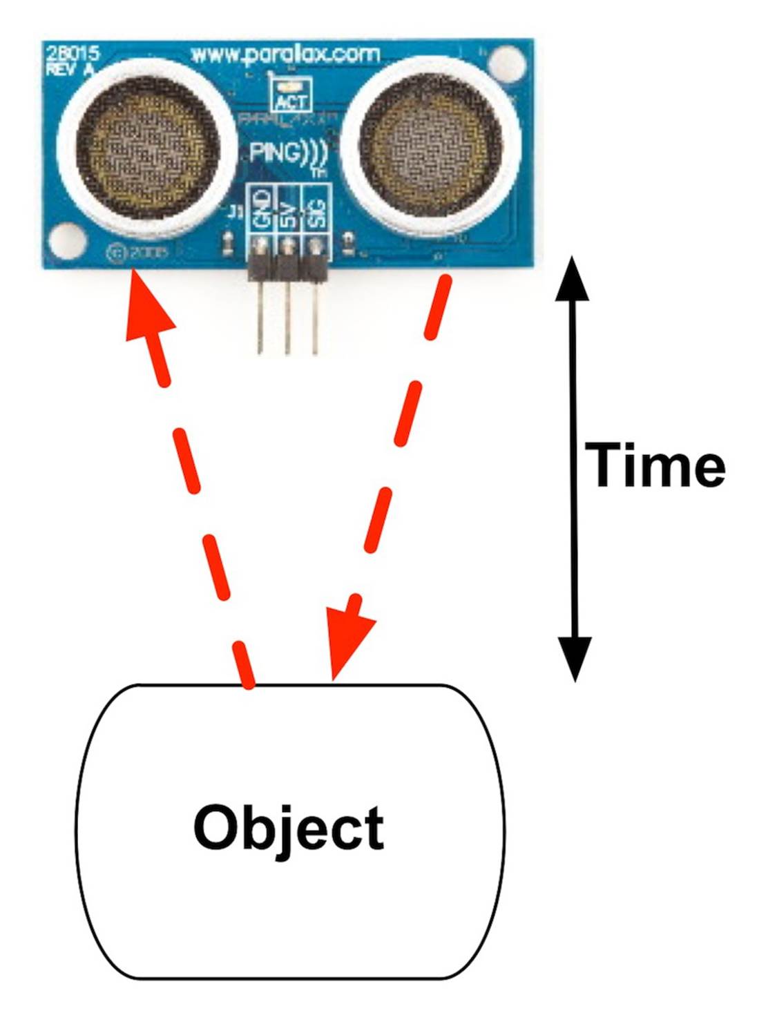
As mentioned earlier, ultrasonic sensors usually don’t return the distance to the nearest object. Instead, they return the time the sound needed to travel to the object and back to the sensor. The PING))) is no exception, and its innards are fairly complex. Fortunately, they are hidden behind three simple pins: power, ground, and signal.
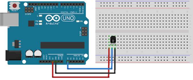
This makes it easy to connect the sensor to the Arduino. First, connect Arduino’s ground and 5V power supply to the corresponding PING))) pins. Then connect the PING)))’s sensor pin to one of the Arduino’s digital IO pins. (We’re using pin 7 for no particular reason.) For a diagram and for a photo of our circuit, see Figure 15, PING))) basic circuit and Figure 16, Photo of PING))) basic circuit.
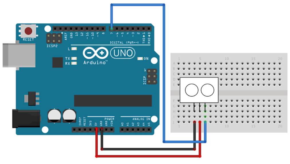
Figure 15. PING))) basic circuit
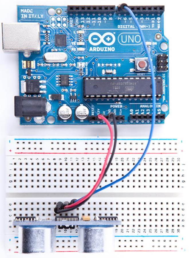
Figure 16. Photo of PING))) basic circuit
To bring the circuit to life, we need some code that communicates with the PING))) sensor:
|
InputDevices/Ultrasonic/Simple/Simple.ino |
|
|
Line 1 |
const unsigned int PING_SENSOR_IO_PIN = 7; |
|
- |
const unsigned int BAUD_RATE = 9600; |
|
- |
|
|
- |
void setup() { |
|
5 |
Serial.begin(BAUD_RATE); |
|
- |
} |
|
- |
|
|
- |
void loop() { |
|
- |
pinMode(PING_SENSOR_IO_PIN, OUTPUT); |
|
10 |
digitalWrite(PING_SENSOR_IO_PIN, LOW); |
|
- |
delayMicroseconds(2); |
|
- |
|
|
- |
digitalWrite(PING_SENSOR_IO_PIN, HIGH); |
|
- |
delayMicroseconds(5); |
|
15 |
digitalWrite(PING_SENSOR_IO_PIN, LOW); |
|
- |
|
|
- |
pinMode(PING_SENSOR_IO_PIN, INPUT); |
|
- |
const unsigned long duration = pulseIn(PING_SENSOR_IO_PIN, HIGH); |
|
- |
if (duration == 0) { |
|
20 |
Serial.println("Warning: We did not get a pulse from sensor."); |
|
- |
} else { |
|
- |
Serial.print("Distance to nearest object: "); |
|
- |
Serial.print(microseconds_to_cm(duration)); |
|
- |
Serial.println(" cm"); |
|
25 |
} |
|
- |
|
|
- |
delay(100); |
|
- |
} |
|
- |
|
|
30 |
unsigned long microseconds_to_cm(const unsigned long microseconds) { |
|
- |
return microseconds / 29 / 2; |
|
- |
} |
First we define a constant for the IO pin the PING))) sensor is connected to. If you want to connect your sensor to another digital IO pin, you have to change the program’s first line. In the setup method, we set the serial port’s baud rate to 9600, because we’d like to see some sensor data on the serial monitor.
The real action happens in loop, where we actually implement the PING))) protocol. According to the data sheet,[57] we can control the sensor using pulses, and it returns results as variable-width pulses, too.
In lines 9 to 11, we set the sensor’s signal pin to LOW for 2 microseconds to bring it to a proper state. This will ensure clean HIGH pulses that are needed in the next steps. (In the world of electronics, you should always be prepared for jitters in the power supply.)
Finally, it’s time to tell the sensor to do some work. In lines 13 to 15, we set the sensor’s signal pin to HIGH for 5 microseconds to start a new measurement. Afterward, we set the pin to LOW again, because the sensor will respond with a HIGH pulse of variable length on the same pin.
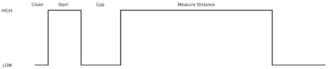
With a digital pin, you have only a few options to transmit information. You can set the pin to HIGH or LOW, and you can control how long it remains in a particular state. For many purposes, this is absolutely sufficient, and in our case it is, too. When the PING))) sensor sends out its 40-kHz chirp, it sets the signal pin to HIGH and then sets it back to LOW when it receives the echo. That is, the signal pin remains in a HIGH state for exactly the time it takes the sound to travel to an object and back to the sensor. Loosely speaking, we are using a digital pin for measuring an analog signal. In the following figure, you can see a diagram showing typical activity on a digital pin connected to a PING))) sensor.
We could measure the duration the pin remains in HIGH state manually, but the pulseIn method already does all the dirty work for us. So, we use it in line 18 after we have set the signal pin into input mode again. pulseIn accepts three parameters:
· pin: Number of the pin to read the pulse from.
· type: Type of the pulse that should be read. It can be HIGH or LOW.
· timeout: Timeout measured in microseconds. If no pulse could be detected within the timeout period, pulseIn returns 0. This parameter is optional and defaults to one second.
Note that in the whole process, only one pin is used to communicate with the PING))). Sooner or later, you’ll realize that IO pins are a scarce resource on the Arduino, so it’s really a nice feature that the PING))) uses only one digital pin. When you can choose between different parts performing the same task, try to use as few pins as possible.
We have only one thing left to do: convert the duration we have measured into a length. Sound travels at 343 meters per second, which means it needs 29.155 microseconds per centimeter. So, we have to divide the duration by 29 and then by 2, because the sound has to travel the distance twice. It travels to the object and then back to the PING))) sensor. The microseconds_to_cm method performs the calculation.
According to the specification of the PING))) sensor, you have to wait at least 200 microseconds between two measurements. For high-speed measurements, we could calculate the length of a pause more accurately by actually measuring the time the code takes. But in our case this is pointless, because all the statements that are executed during two measurements in the loop method take far more than 200 microseconds. And outputting data to the serial connection is fairly expensive. Despite this, we have added a small delay of 100 microseconds to slow down the output.
You might wonder why we use the const keyword so often. To program the Arduino you use C/C++, and in these languages it’s considered a good practice to declare constant values as const (see Effective C++: 50 Specific Ways to Improve Your Programs and Designs [Mey97]). Not only will using const make your program more concise and prevent logical errors early, but it will also help the compiler to decrease your program’s size.
Although most Arduino programs are comparatively small, software development for the Arduino is still software development, and it should be done according to all the best practices we know. So, whenever you define a constant value in your program, declare it as such (using const, not using #define). This is true for other programming languages as well, so we will use final in our Java programs, too.
Now it’s time to play around with the sensor and get familiar with its strengths and weaknesses. Compile the program, upload it to your Arduino board, and open the serial monitor (don’t forget to set the baud rate to 9600). You should see something like this:
|
|
Distance to nearest object: 42 cm |
|
|
Distance to nearest object: 33 cm |
|
|
Distance to nearest object: 27 cm |
|
|
Distance to nearest object: 27 cm |
|
|
Distance to nearest object: 29 cm |
|
|
Distance to nearest object: 36 cm |
In addition to the output in the terminal, you will see that the LED on the PING))) sensor is turned on whenever the sensor starts a new measurement.
Test the sensor’s capabilities by trying to detect big things or very small things. Try to detect objects from different angles, and try to detect objects that are below or above the sensor. You should also do some experiments with objects that don’t have a flat surface. Try to detect stuffed animals, and you will see that they are not detected as well as solid objects. (That’s probably why bats don’t hunt bears—they can’t see them.)
With only three wires and a few lines of code, we have built a first version of a digital metering rule. At the moment, it outputs only centimeter distances in whole numbers, but we’ll increase its accuracy tremendously in the next section by changing our software and adding more hardware.
Increasing Precision Using Floating-Point Numbers
According to the specification, the PING))) sensor is accurate for objects that are between 2 centimeters and 3 meters away. (By the way, the reason for this is the length of the pulse that is generated. Its minimum length is 115 microseconds, and the maximum length is 18.5 milliseconds.) With our current approach, we don’t fully benefit from its precision because all calculations are performed using integer values. We can only measure distances with an accuracy of a centimeter. To enter the millimeter range, we have to use floating-point numbers.
Normally it’s a good idea to use integer operations, because compared to regular computers the Arduino’s memory and CPU capacities are severely limited and calculations containing floating-point numbers are often expensive. But sometimes it’s useful to enjoy the luxury of highly accurate floating-point numbers, and the Arduino supports them well. We’ll use them to improve our project now:
|
InputDevices/Ultrasonic/Float/Float.ino |
|
|
Line 1 |
const unsigned int PING_SENSOR_IO_PIN = 7; |
|
- |
const unsigned int BAUD_RATE = 9600; |
|
- |
const float MICROSECONDS_PER_CM = 29.155; |
|
- |
const float MOUNTING_GAP = 0.2; |
|
5 |
const float SENSOR_OFFSET = MOUNTING_GAP * MICROSECONDS_PER_CM * 2; |
|
- |
|
|
- |
void setup() { |
|
- |
Serial.begin(BAUD_RATE); |
|
- |
} |
|
10 |
void loop() { |
|
- |
const unsigned long duration = measure_distance(); |
|
- |
if (duration == 0) |
|
- |
Serial.println("Warning: We did not get a pulse from sensor."); |
|
- |
else |
|
15 |
output_distance(duration); |
|
- |
} |
|
- |
|
|
- |
const float microseconds_to_cm(const unsigned long microseconds) { |
|
- |
const float net_distance = max(0, microseconds - SENSOR_OFFSET); |
|
20 |
return net_distance / MICROSECONDS_PER_CM / 2; |
|
- |
} |
|
- |
|
|
- |
|
|
- |
const unsigned long measure_distance() { |
|
25 |
pinMode(PING_SENSOR_IO_PIN, OUTPUT); |
|
- |
digitalWrite(PING_SENSOR_IO_PIN, LOW); |
|
- |
delayMicroseconds(2); |
|
- |
digitalWrite(PING_SENSOR_IO_PIN, HIGH); |
|
- |
delayMicroseconds(5); |
|
30 |
digitalWrite(PING_SENSOR_IO_PIN, LOW); |
|
- |
pinMode(PING_SENSOR_IO_PIN, INPUT); |
|
- |
return pulseIn(PING_SENSOR_IO_PIN, HIGH); |
|
- |
} |
|
- |
|
|
35 |
void output_distance(const unsigned long duration) { |
|
- |
Serial.print("Distance to nearest object: "); |
|
- |
Serial.print(microseconds_to_cm(duration)); |
|
- |
Serial.println(" cm"); |
|
- |
} |
This program doesn’t differ much from our first version. First, we use the more accurate value 29.155 for the number of microseconds it takes sound to travel 1 centimeter. In addition, the distance calculation now takes a potential gap between the sensor and the case into account. If you plug the sensor into a breadboard, usually a small gap between the sensor and the breadboard’s edge exists. This gap is defined in line 5, and it will be used in the distance calculation later on. The gap is measured in centimeters, and it gets multiplied by two because the sound travels out and back.
The loop method looks much cleaner now, because the program’s main functionality has been moved to separate functions. The whole sensor control logic lives in the measure_distance method, and output_distance takes care of outputting values to the serial port. The big changes happened in the microseconds_to_cm function. It returns a float value now, and it subtracts the sensor gap from the measured duration. To make sure we don’t get negative values, we use the max function.
Compile and upload the program, and you should see something like the following in your serial monitor window:
|
|
Distance to nearest object: 17.26 cm |
|
|
Distance to nearest object: 17.93 cm |
|
|
Distance to nearest object: 17.79 cm |
|
|
Distance to nearest object: 18.17 cm |
|
|
Distance to nearest object: 18.65 cm |
|
|
Distance to nearest object: 18.85 cm |
This not only looks more accurate than our previous version, it actually is more accurate. If you have worked with floating-point numbers in any programming language before, you might ask yourself why the Arduino rounds them automatically to two decimal digits. The secret lies in theprint method of the Serial class. In recent versions of the Arduino platform, it works for all possible data types, and when it receives a float variable, it rounds it to two decimal digits before it gets output. You can specify the number of decimal digits. For example, Serial.println(3.141592, 4);prints 3.1416.
Only the output is affected by this; internally it is still a float variable. By the way, on most Arduinos, float and double values are the same at the moment. Only on the Arduino Due is double more accurate than float.
So, what does it actually cost to use float variables? Their memory consumption is 4 bytes—that is, they consume as much memory as long variables. On the other hand, floating-point calculations are fairly expensive and should be avoided in time-critical parts of your software. The biggest costs are the additional library functions that have to be linked to your program for float support. Serial.print(3.14) might look harmless, but it increases your program’s size tremendously.
Comment line 37 out and recompile the program to see the effect. It will no longer work properly, but we can see how this statement affects the program size. With my current setup, it needs 3,002 bytes without float support for Serial.print and 5,070 bytes otherwise. That’s a difference of 2,068 bytes!
In some cases, you can still get the best of both worlds: float support without paying the memory tax. You can save a lot of space by converting the float values to integers before sending them over a serial connection. To transfer values with a precision of two digits, multiply them by 100, and don’t forget to divide them by 100 on the receiving side. We’ll use this trick (including rounding) later.
Increasing Precision Using a Temperature Sensor
Support for floating-point numbers is an improvement, but it mainly increases the precision of our program’s output. We could’ve achieved a similar effect using some integer math tricks. But now we’ll add an even better improvement that cannot be imitated using software: a temperature sensor.
When I told you that sound travels through air at 343 m/s, I wasn’t totally accurate, because the speed of sound isn’t constant—among other things, it depends on the air’s temperature. If you don’t take temperature into account, the error can grow up to a quite significant 12 percent. We calculate the actual speed of sound C with a simple formula:
C = 331.5 + (0.6 * t)
To use it, we only have to determine the current temperature t in Celsius. We will use the TMP36 voltage output temperature sensor from Analog Devices.[58] It’s cheap and easy to use.
To connect the TMP36 to the Arduino, connect the Arduino’s ground and power to the corresponding pins of the TMP36. Then connect the sensor’s signal pin to the pin A0—that is, the analog pin number 0:
As you might’ve guessed from its vendor’s name, the TMP36 is an analog device: it changes the voltage on its signal pin corresponding to the current temperature. The higher the temperature, the higher the voltage. For us, it’s an excellent opportunity to learn how to use the Arduino’s analog IO pins. So, let’s see some code that uses the sensor:
|
InputDevices/Temperature/SensorTest/SensorTest.ino |
|
|
Line 1 |
const unsigned int TEMP_SENSOR_PIN = A0; |
|
- |
const float SUPPLY_VOLTAGE = 5.0; |
|
- |
const unsigned int BAUD_RATE = 9600; |
|
- |
|
|
5 |
void setup() { |
|
- |
Serial.begin(BAUD_RATE); |
|
- |
} |
|
- |
|
|
- |
void loop() { |
|
10 |
const float tempC = get_temperature(); |
|
- |
const float tempF = (tempC * 9.0 / 5.0) + 32.0; |
|
- |
Serial.print(tempC); |
|
- |
Serial.print(" C, "); |
|
- |
Serial.print(tempF); |
|
15 |
Serial.println(" F"); |
|
- |
delay(1000); |
|
- |
} |
|
- |
|
|
- |
const float get_temperature() { |
|
20 |
const int sensor_voltage = analogRead(TEMP_SENSOR_PIN); |
|
- |
const float voltage = sensor_voltage * SUPPLY_VOLTAGE / 1024; |
|
- |
return (voltage * 1000 - 500) / 10; |
|
- |
} |
In the first two lines, we define constants for the analog pin the sensor is connected to and for the Arduino’s supply voltage. Then we have a pretty normal setup method followed by a loop method that outputs the current temperature every second. The whole sensor logic has been encapsulated in the get_temperature method. It returns the temperature in degrees Celsius, and we convert it to a Fahrenheit value, too.
For the PING))) sensor, we only needed a digital pin that could be HIGH or LOW. Analog pins are different and represent a voltage ranging from 0V to the current power supply (usually 5V). We can read the Arduino’s analog pins using the analogRead method that returns a value between 0 and 1023, because analog pins have a resolution of 10 bits (1024 = 210). We use it in line 20 to read the current voltage supplied by the TMP36.
How to Encode Sensor Data
Encoding sensor data is a problem that has to be solved often in Arduino projects, because all the nice data we collect usually has to be interpreted by applications running on regular computers.
When defining a data format, you have to take several things into account. Among others, the format shouldn’t waste the Arduino’s precious memory. In our case, we could’ve used XML for encoding the sensor data:
|
|
<sensor-data> |
|
|
<temperature>30.05</temperature> |
|
|
<distance>51.19</distance> |
|
|
</sensor-data> |
Obviously this isn’t a good choice, because now we’re wasting a multiple of the actual data’s memory for creating the file format’s structure. In addition, the receiving application has to use an XML parser to interpret the data.
But you shouldn’t go to the other extreme, either. That is, you should use binary formats only if absolutely necessary or if the receiving application expects binary data anyway.
All in all, the simplest data formats, such as character-separated values (CSV), are often the best choice.
There’s one problem left, though: we have to turn the value returned by analogRead into an actual voltage value, so we must know the Arduino’s current power supply. It usually is 5V, but there are Arduino models (such as the Arduino Pro, for example) that use only 3.3V. You have to adjust the constant SUPPLY_VOLTAGE accordingly.
We can turn the analog pin’s output into a voltage value by dividing it by 1024 and by multiplying it by the supply voltage, which we do in line 21.
We now have to convert the voltage the sensor delivers into degrees Celsius. In the sensor’s data sheet, we find the following formula:
T = ((sensor output in mV) - 500) / 10
We have to subtract 500 millivolts because the sensor always outputs a positive voltage. This way, we can represent negative temperatures, too. The sensor’s resolution is 10 millivolts, so we have to divide by 10. A voltage value of 750 millivolts corresponds to a temperature of (750 - 500) / 10 = 25°C. See it implemented in line 22.
Compile the program, upload it to the Arduino, and you’ll see something like the following in your serial monitor:
|
|
20.80 C, 69.44 F |
|
|
20.80 C, 69.44 F |
|
|
20.31 C, 68.56 F |
|
|
20.80 C, 69.44 F |
|
|
20.80 C, 69.44 F |
As you can see, the sensor needs some time to calibrate, but its results get stable fairly quickly. By the way, you’ll always need to insert a short delay between two calls to analogRead, because the Arduino’s internal analog system needs some time (0.0001 seconds on the Uno) between two readings. We use a delay of a whole second to make the output easier to read and because we don’t expect the temperature to change rapidly. Otherwise, a delay of a single millisecond would be enough.
Now we have two separate circuits: one for measuring distances and one for measuring temperatures. See them combined to a single circuit in Figure 17, The TMP36 and the PING))) sensors working together and Figure 18, Photo of final circuit.
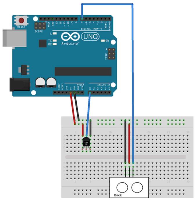
Figure 17. The TMP36 and the PING))) sensors working together
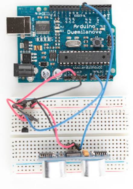
Figure 18. Photo of final circuit
Use the following program to bring the circuit to life:
|
InputDevices/Ultrasonic/PreciseSensor/PreciseSensor.ino |
|
|
Line 1 |
const unsigned int TEMP_SENSOR_PIN = A0; |
|
- |
const float SUPPLY_VOLTAGE = 5.0; |
|
- |
const unsigned int PING_SENSOR_IO_PIN = 7; |
|
- |
const float SENSOR_GAP = 0.2; |
|
5 |
const unsigned int BAUD_RATE = 9600; |
|
- |
float current_temperature = 0.0; |
|
- |
unsigned long last_measurement = millis(); |
|
- |
|
|
- |
|
|
10 |
void setup() { |
|
- |
Serial.begin(BAUD_RATE); |
|
- |
} |
|
- |
|
|
- |
void loop() { |
|
15 |
unsigned long current_millis = millis(); |
|
- |
if (abs(current_millis - last_measurement) >= 1000) { |
|
- |
current_temperature = get_temperature(); |
|
- |
last_measurement = current_millis; |
|
- |
} |
|
20 |
Serial.print(scaled_value(current_temperature)); |
|
- |
Serial.print(","); |
|
- |
const unsigned long duration = measure_distance(); |
|
- |
Serial.println(scaled_value(microseconds_to_cm(duration))); |
|
- |
} |
|
25 |
|
|
- |
long scaled_value(const float value) { |
|
- |
float round_offset = value < 0 ? -0.5 : 0.5; |
|
- |
return (long)(value * 100 + round_offset); |
|
- |
} |
|
30 |
|
|
- |
const float get_temperature() { |
|
- |
const int sensor_voltage = analogRead(TEMP_SENSOR_PIN); |
|
- |
const float voltage = sensor_voltage * SUPPLY_VOLTAGE / 1024; |
|
- |
return (voltage * 1000 - 500) / 10; |
|
35 |
} |
|
- |
|
|
- |
const float microseconds_per_cm() { |
|
- |
return 1 / ((331.5 + (0.6 * current_temperature)) / 10000); |
|
- |
} |
|
40 |
|
|
- |
const float sensor_offset() { |
|
- |
return SENSOR_GAP * microseconds_per_cm() * 2; |
|
- |
} |
|
- |
|
|
45 |
const float microseconds_to_cm(const unsigned long microseconds) { |
|
- |
const float net_distance = max(0, microseconds - sensor_offset()); |
|
- |
return net_distance / microseconds_per_cm() / 2; |
|
- |
} |
|
- |
|
|
50 |
const unsigned long measure_distance() { |
|
- |
pinMode(PING_SENSOR_IO_PIN, OUTPUT); |
|
- |
digitalWrite(PING_SENSOR_IO_PIN, LOW); |
|
- |
delayMicroseconds(2); |
|
- |
digitalWrite(PING_SENSOR_IO_PIN, HIGH); |
|
55 |
delayMicroseconds(5); |
|
- |
digitalWrite(PING_SENSOR_IO_PIN, LOW); |
|
- |
pinMode(PING_SENSOR_IO_PIN, INPUT); |
|
- |
return pulseIn(PING_SENSOR_IO_PIN, HIGH); |
|
- |
} |
The code is nearly a perfect merge of the programs we used to get the PING))) and the TMP36 sensors working. Only a few things were changed:
· The constant MICROSECONDS_PER_CM has been replaced by the microseconds_per_cm function, which determines the microseconds sound needs to travel 1 centimeter dynamically, depending on the current temperature.
· Because the current temperature usually won’t change often or rapidly, we don’t measure it permanently, but only once a second. We use millis in line 7 to determine the number of milliseconds that have passed since the Arduino started. From lines 15 to 19, we check whether more than a second has passed since the last measurement. If yes, we measure the current temperature again.
· We no longer transfer the sensor data as floating-point numbers on the serial port, but instead use scaled integer values. This is done by the scaled_value function, which rounds a float value to two decimal digits and converts it into a long value by multiplying it by 100. On the receiving side, you have to divide it by 100 again.
If you upload the program to your Arduino and play around with your hand in front of the sensor, you’ll see an output similar to the following:
|
|
2129,1016 |
|
|
2129,1027 |
|
|
2129,1071 |
|
|
2129,1063 |
|
|
2129,1063 |
|
|
2129,1063 |
The output is a comma-separated list of values where the first value represents the current temperature in degree Celsius, and the second is the distance to the nearest object measured in centimeters. Both values have to be divided by 100 to get the actual sensor data.
Our little project now has two sensors. One is connected to a digital pin, while the other uses an analog one. In the next section, you’ll learn how to transfer sensor data back to a PC and use it to create applications based on the current state of the real world.
Save the Climate Using Sonar Sensors
Researchers from Northwestern University and University of Michigan have created a sonar system that uses only a computer’s microphone and speakers to detect whether the computer is currently used.[59] If it’s not being used, the computer automatically powers off its screen, saving the environment.
Instead of using a microphone and speakers, you can also use a PING))) sensor. With the lessons you’ve learned in this chapter, you can build such a system yourself with ease. Try it!
Creating Your Own Dashboard
Instead of printing our digital and analog sensor data to a serial port, we’ll simulate a small part of a modern car’s dashboard in this section. Most cars today show the current temperature, and many also have a parking-distance control system that warns you if you get too close to another object.
In my car, the parking-distance control consists of a couple of orange and red LEDs. If nothing’s near the car, all LEDs are off. As soon as the distance between the car and a potential obstacle gets too small, the first orange LED lights up. The shorter the distance, the more LEDs that light up. If the distance reaches a critical limit, all LEDs are on, and the car plays an annoying beep tone.
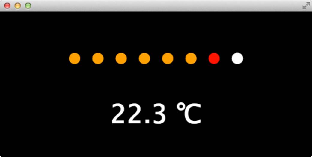
Here’s the application we’re going to build. It shows the current temperature, and you can also see that the first red light is already on, indicating that there’s something very close to the distance sensor.
We’ll implement the application as a Google Chrome app. (Now is a good time to read Appendix 4, Controlling the Arduino with a Browser, if you haven’t done so already.) The application’s manifest.json file contains no surprises:
|
InputDevices/Dashboard/manifest.json |
|
|
|
{ |
|
|
"manifest_version": 2, |
|
|
"name": "Dashboard Demo", |
|
|
"version": "1", |
|
|
"permissions": [ "serial" ], |
|
|
"app": { |
|
|
"background": { |
|
|
"scripts": ["background.js"] |
|
|
} |
|
|
}, |
|
|
"minimum_chrome_version": "33" |
|
|
} |
It defines all meta information needed, and it declares that the Chrome App needs to access the serial port. The background.js file isn’t very exciting, either:
|
InputDevices/Dashboard/background.js |
|
|
|
chrome.app.runtime.onLaunched.addListener(function() { |
|
|
chrome.app.window.create('main.html', { |
|
|
id: 'main', |
|
|
bounds: { width: 600, height: 300 } |
|
|
}); |
|
|
}); |
It opens a new window and displays the main.html file:
|
InputDevices/Dashboard/main.html |
|
|
Line 1 |
<!DOCTYPE html> |
|
- |
<html lang="en"> |
|
- |
<head> |
|
- |
<meta charset="utf-8"/> |
|
5 |
<link rel="stylesheet" type="text/css" href="css/dashboard.css"/> |
|
- |
<title>Dashboard Demo</title> |
|
- |
</head> |
|
- |
<body> |
|
- |
<div id="dashboard"> |
|
10 |
<div id="distance-display"> |
|
- |
<p> |
|
- |
<span id="d1">●</span> |
|
- |
<span id="d2">●</span> |
|
- |
<span id="d3">●</span> |
|
15 |
<span id="d4">●</span> |
|
- |
<span id="d5">●</span> |
|
- |
<span id="d6">●</span> |
|
- |
<span id="d7">●</span> |
|
- |
<span id="d8">●</span> |
|
20 |
</p> |
|
- |
</div> |
|
- |
<div id="temperature-display"> |
|
- |
<p><span id="temperature"></span> ℃</p> |
|
- |
</div> |
|
25 |
</div> |
|
- |
<script src="js/serial_device.js"></script> |
|
- |
<script src="js/dashboard.js"></script> |
|
- |
</body> |
|
- |
</html> |
To create the dashboard’s user interface, we need only some basic HTML. We define the whole parking-distance control display in lines 12 to 19. We represent each LED by a <span> element containing the Unicode character (●) for a filled circle. Each <span> element gets a unique ID, so we can refer to the individual LEDs later on.
The temperature display is even simpler. It consists of a single <span> element. We’ve added the Unicode character for a degrees Celsius symbol (℃) to make it look more professional. Let’s add a little bit of CSS to make the dashboard even more appealing:
|
InputDevices/Dashboard/css/dashboard.css |
|
|
|
body { |
|
|
font-size: 50px; |
|
|
background: black; |
|
|
color: white; |
|
|
} |
|
|
|
|
|
#distance-display, |
|
|
#temperature-display { |
|
|
text-align: center; |
|
|
} |
The stylesheet increases the font size and sets the background color to black and the text color to white. Also, it centers both the LED display and the temperature display.
Now it’s time to bring the dashboard to life using some JavaScript:
|
InputDevices/Dashboard/js/dashboard.js |
|
|
Line 1 |
var arduino = new SerialDevice("/dev/tty.usbmodem24321", 9600); |
|
- |
|
|
- |
arduino.onConnect.addListener(function() { |
|
- |
console.log("Connected to: " + arduino.path); |
|
5 |
}); |
|
- |
|
|
- |
arduino.onReadLine.addListener(function(line) { |
|
- |
console.log("Read line: " + line); |
|
- |
var attr = line.split(","); |
|
10 |
if (attr.length == 2) { |
|
- |
var temperature = Math.round(parseInt(attr[0]) / 100.0 * 10) / 10; |
|
- |
var distance = parseInt(attr[1]) / 100.0; |
|
- |
updateUI(temperature, distance); |
|
- |
} |
|
15 |
}); |
|
- |
|
|
- |
var lights = { |
|
- |
d1: [35.0, "orange"], |
|
- |
d2: [30.0, "orange"], |
|
20 |
d3: [25.0, "orange"], |
|
- |
d4: [20.0, "orange"], |
|
- |
d5: [15.0, "orange"], |
|
- |
d6: [10.0, "orange"], |
|
- |
d7: [7.0, "red"], |
|
25 |
d8: [5.0, "red"] |
|
- |
}; |
|
- |
|
|
- |
function updateUI(temperature, distance) { |
|
- |
document.getElementById("temperature").innerText = temperature; |
|
30 |
for (var i = 1; i < 9; i++) { |
|
- |
var index = "d" + i; |
|
- |
if (distance <= lights[index][0]) |
|
- |
document.getElementById(index).style.color = lights[index][1]; |
|
- |
else |
|
35 |
document.getElementById(index).style.color = "white"; |
|
- |
} |
|
- |
} |
|
- |
|
|
- |
arduino.connect(); |
To read the sensor data from the Arduino, we use the SerialDevice class we’ve defined in Writing a SerialDevice Class. We create a new instance named arduino in the first line. Make sure you’re using the right serial port path.
Then we define an onConnect handler that prints a message to the browser’s JavaScript console as soon as the application has connected to an Arduino. In principle, you don’t need the onConnect handler. In this case, it’s mostly useful for debugging purposes.
Things get more interesting in the onReadLine handler. In line 9, we split the data we’ve received from the Arduino. We make sure that we’ve actually received two values. In this case we turn both values into numbers using parseInt, and we also divide them by 100 because the Arduino sends values that have been multiplied by 100 before. In line 11, we use a popular JavaScript trick to round the temperature value to one decimal digit. After we’ve turned both the distance and the temperature into proper numbers, we pass them to updateUI.
updateUI sets the new temperature value first in line 29. To do this, it looks up the HTML element having the ID temperature using the getElementById function. Then it sets the element’s innerText property to the current temperature.
Updating the artificial LED display is a bit more complex, but not too difficult. We’ve defined a data structure named lights that maps the IDs of our display’s <span> elements to arrays having two elements each. For example, it maps the ID d1 to an array containing the values 35.0 and “orange”. That means that the color of the element having the ID d1 will be set to orange when the distance to the next object is less than or equal 35.0 centimeters.
Using the lights data structure, it’s easy to implement the LED display. In line 30, we start a loop iterating over all LEDs. We determine the current LED’s ID in line 31. Then we check whether the current distance is less than or equal to the threshold value that belongs to the current LED. If yes, we change the LED’s color accordingly. Otherwise, we set its color to white.
Some Fun with Sensors
With an ultrasonic sensor, you can easily detect whether someone is nearby. This automatically brings a lot of useful applications to mind. You could open a door automatically as soon as someone is close enough, for example.
Alternatively, you can use advanced technology for pure fun. What about some Halloween gimmicks, such as a pumpkin that shoots silly string whenever you cross an invisible line?[60] It could be a nice gag for your next party, and you can build it using the PING))) sensor.
Connect the Arduino to your computer and upload the sketch we developed in the previous section. Start the Chrome App and move your hand back and forth in front of the PING))) sensor. The display on the screen will look exactly like the display in a typical car.
Sensors are an exciting topic, and in this chapter you’ve learned the basics of working with both analog and digital sensors. In the next chapter, we’ll build on that foundation and connect the Arduino to an accelerometer to create a motion-sensing game controller.
What If It Doesn’t Work?
See What If It Doesn’t Work?, and make sure that you’ve connected all parts properly to the breadboard. Take special care with the PING))) and the TMP36 sensors, because you haven’t worked with them before. Make sure you’ve connected the right pins to the right connectors of the sensors.
In case of any errors with the software—no matter whether it’s JavaScript or Arduino code—download the code from the book’s website and see whether it works.
If you have problems with serial communication, double-check whether you’ve used the right serial port and the right Arduino type. Remember to adjust the path to your Arduino’s serial port in the first line of dashboard.js. Also check whether the baud rate in the JavaScript code matches the baud rate you’ve used in the Arduino code.
Make sure that the serial port isn’t blocked by another application, such as a serial monitor window you forgot to close.
Exercises
· Build an automatic burglar alarm that shows a stop sign whenever someone is too close to your computer.[61] Make the application as smart as possible. It should have a small activation delay to prevent it from showing a stop sign immediately when it’s started.
· The speed of sound depends not only on the temperature, but also on humidity and atmospheric pressure. Do some research to find the right formula and the right sensors. Use your research results to make the circuit for measuring distances even more precise.
· Use an alternative technology for measuring distances—for example, an infrared sensor. Try to find an appropriate sensor, read its data sheet, and build a basic circuit so you can print the distance to the nearest object to the serial port.
Footnotes
|
[56] |
http://www.parallax.com/product/28015 |
|
[57] |
http://www.parallax.com/downloads/ping-ultrasonic-distance-sensor-product-guide |
|
[58] |
http://tinyurl.com/msard-analog |
|
[59] |
http://blog.makezine.com/2009/10/15/using-sonar-to-save-power/ |
|
[60] |
http://www.instructables.com/id/Arduino-controlled-Silly-String-shooter/ |
|
[61] |
You can find a stop sign here: http://en.wikipedia.org/wiki/File:Stop_sign_MUTCD.svg. |
All materials on the site are licensed Creative Commons Attribution-Sharealike 3.0 Unported CC BY-SA 3.0 & GNU Free Documentation License (GFDL)
If you are the copyright holder of any material contained on our site and intend to remove it, please contact our site administrator for approval.
© 2016-2026 All site design rights belong to S.Y.A.