Arduino: A Quick-Start Guide, Second Edition (2015)
Part II. Eleven Arduino Projects
Chapter 6. Building a Motion-Sensing Game Controller
It’s astonishing how quickly we get used to new technologies. A decade ago, not many people would’ve imagined that we would use devices someday to follow our movements. Today, it’s absolutely normal for us to physically turn our smartphones when we want to change from portrait to landscape view. Even small children intuitively know how to use motion-sensing controllers for video game consoles, such as Nintendo’s Wii. You can build your own motion-sensing devices using an Arduino, and in this chapter you’ll learn how.
We’ll work with one of the most widespread motion-sensing devices: the accelerometer. Accelerometers detect movement in all directions—they notice if you move them up or down (Z-axis), forward or backward (Y-axis), and to the left or to the right (X-axis). Many popular gadgets, such as the iPhone and the Nintendo Wii controllers, contain accelerometers, so accelerometers are produced in large quantities. That’s why they’re cheap.
Both fun and serious projects can benefit from accelerometers. When working with your computer, you certainly think of devices, such as game controllers or other input control devices, that you connect via USB. But you can also use them when exercising or to control a real-life marble maze. They are also the right tool for measuring acceleration indirectly, such as in a car.
You will learn how to interpret accelerometer data correctly and how to get the most accurate results. Then you’ll use an accelerometer to build a motion-sensing game controller, and in the next chapter you’ll implement a game that uses it.
What You Need
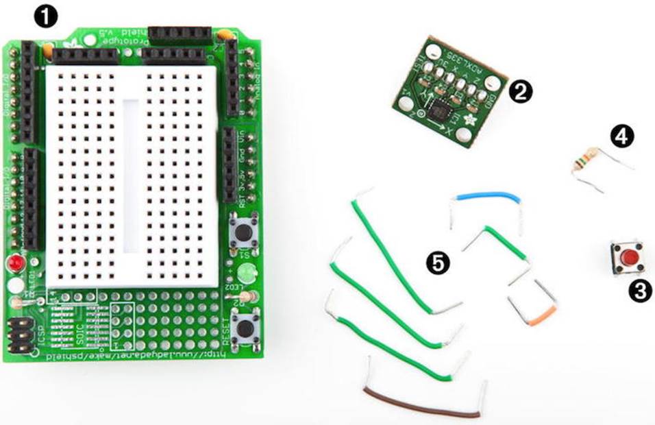
1. An Arduino Proto Shield (optional)
2. An ADXL335 accelerometer
3. A pushbutton
4. A 10kΩ resistor
5. Some wires
6. A half-size breadboard (if you’re not using a Proto Shield)
7. An Arduino board, such as the Uno, Duemilanove, or Diecimila
8. A USB cable to connect the Arduino to your computer
9. A 6-pin 0.1-inch standard header
Wiring Up the Accelerometer
There are many different accelerometers, differing mainly in the number of spatial axes they support (usually two or three). I’ll use the ADXL335 from Analog Devices—it’s easy to use and widely available.[62] Analog Devices offers many more accelerometers, named ADXL345, ADXL377, or ADXL326, for example. They all work the same, and they differ only in accuracy and price.
In this section, we’ll connect the ADXL335 to the Arduino and create a small demo program showing the raw data the sensor delivers. At that point, we will have a quick look at the sensor’s specification and interpret the data.
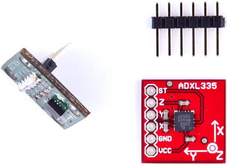
This picture shows a breakout board containing an ADXL335 sensor on the right. The sensor is the small black integrated circuit (IC), and the rest is just a carrier to allow connections. On the top, you see a 6-pin 0.1-inch standard header. The sensor has six connectors, labeled GND, Z, Y, X, VCC, and ST. To use the sensor on a breadboard, solder the standard header to the connectors. This not only makes it easier to attach the sensor to a breadboard, but it also stabilizes the sensor so it doesn’t move accidentally. You can see the result on the left side of the photo. (Note that the breakout board on the left isn’t the same as on the right, but it’s very similar.) Don’t worry if you’ve never soldered before. In Learning How to Solder, you can learn how to do it.
You can ignore the connector labeled ST, and the meaning of the remaining connectors should be obvious. To power the sensor, connect GND to the Arduino’s ground pin and VCC to the Arduino’s 3.3V power supply. X, Y, and Z will then deliver acceleration data for the x-, y-, and z-axes.
Note that not all breakout boards have the same connectors. Usually, they have six or seven connectors. Some breakout boards can cope with 5V, while others only work with 3.3V. Some boards have an input pin named VIN that you have to connect to one of the Arduino’s power supply pins (5V or 3.3V).
Like the TMP36 temperature sensor we used in Increasing Precision Using a Temperature Sensor, the ADXL335 is an analog device: it delivers results as voltages that have to be converted into acceleration values. So, the X, Y, and Z connectors have to be connected to three analog pins on the Arduino. We connect Z to analog pin 0, Y to analog pin 1, and X to analog pin 2. (See the following image and double-check the pin labels on the breakout board you’re using!) Naturally, you’ll move around the accelerometer a lot, so it’s best to use long wires.
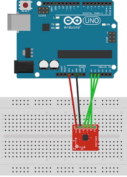
Now that we’ve connected the ADXL335 to the Arduino, let’s use it.
Bringing Your Accelerometer to Life
A pragmatic strategy to get familiar with a new device is to hook it up and see what data it delivers. The following program reads input values for all three axes and outputs them to the serial port:
|
MotionSensor/SensorTest/SensorTest.ino |
|
|
|
const unsigned int X_AXIS_PIN = A2; |
|
|
const unsigned int Y_AXIS_PIN = A1; |
|
|
const unsigned int Z_AXIS_PIN = A0; |
|
|
const unsigned int BAUD_RATE = 9600; |
|
|
|
|
|
void setup() { |
|
|
Serial.begin(BAUD_RATE); |
|
|
} |
|
|
|
|
|
void loop() { |
|
|
Serial.print(analogRead(X_AXIS_PIN)); |
|
|
Serial.print(" "); |
|
|
Serial.print(analogRead(Y_AXIS_PIN)); |
|
|
Serial.print(" "); |
|
|
Serial.println(analogRead(Z_AXIS_PIN)); |
|
|
delay(100); |
|
|
} |
Our test program is as simple as it can be. We define constants for the three analog pins and initialize the serial port in the setup function. Note that we didn’t set the analog pins to INPUT explicitly, because that’s the default anyway.
In the loop function, we constantly output the values we read from the analog pins to the serial port. Open the serial monitor and move the sensor around —tilt it around the different axes. You should see output like this:
|
|
344 331 390 |
|
|
364 276 352 |
|
|
388 286 287 |
|
|
398 314 286 |
|
|
376 332 289 |
|
|
370 336 301 |
These values represent the data we get for the x-, y-, and z-axes. When you move the sensor only around the x-axis, for example, you can see that the first value changes accordingly. In the next section, we’ll take a closer look at these values.
Finding and Polishing Edge Values
The physical world often is far from perfect. That’s especially true for the data many sensors emit, and accelerometers are no exception. They vary slightly in the minimum and maximum values they generate, and they often jitter. They might change their output values even though you haven’t moved them, or they might not change their output values correctly. In this section, we’ll determine the sensor’s minimum and maximum values, and we’ll flatten the jitter.
Finding the edge values of the sensor is easy, but it cannot be easily automated. You have to constantly read the sensor’s output while moving it. Here’s a program that does the job:
|
MotionSensor/SensorValues/SensorValues.ino |
|
|
|
const unsigned int X_AXIS_PIN = A2; |
|
|
const unsigned int Y_AXIS_PIN = A1; |
|
|
const unsigned int Z_AXIS_PIN = A0; |
|
|
const unsigned int BAUD_RATE = 9600; |
|
|
|
|
|
int min_x, min_y, min_z; |
|
|
int max_x, max_y, max_z; |
|
|
|
|
|
void setup() { |
|
|
Serial.begin(BAUD_RATE); |
|
|
min_x = min_y = min_z = 1000; |
|
|
max_x = max_y = max_z = -1000; |
|
|
} |
|
|
|
|
|
void loop() { |
|
|
const int x = analogRead(X_AXIS_PIN); |
|
|
const int y = analogRead(Y_AXIS_PIN); |
|
|
const int z = analogRead(Z_AXIS_PIN); |
|
|
|
|
|
min_x = min(x, min_x); max_x = max(x, max_x); |
|
|
min_y = min(y, min_y); max_y = max(y, max_y); |
|
|
min_z = min(z, min_z); max_z = max(z, max_z); |
|
|
|
|
|
Serial.print("x("); |
|
|
Serial.print(min_x); |
|
|
Serial.print("/"); |
|
|
Serial.print(max_x); |
|
|
Serial.print("), y("); |
|
|
Serial.print(min_y); |
|
|
Serial.print("/"); |
|
|
Serial.print(max_y); |
|
|
Serial.print("), z("); |
|
|
Serial.print(min_z); |
|
|
Serial.print("/"); |
|
|
Serial.print(max_z); |
|
|
Serial.println(")"); |
|
|
} |
We declare variables for the minimum and maximum values of all three axes, and we initialize them with numbers that are definitely out of the sensor’s range (-1000 and 1000). In the loop function, we permanently measure the acceleration of all three axes and adjust the minimum and maximum values accordingly.
Compile and upload the sketch, then move the breadboard with the sensor in all directions, and then tilt it around all axes. Move it slowly, move it fast, tilt it slowly, and tilt it fast. Be careful when moving and rotating the breadboard that you don’t accidentally loosen a connection.
After a short while, the minimum and maximum values will stabilize, and you should get output like this:
|
|
x(247/649), y(253/647), z(278/658) |
Write down these values, because we’ll need them later, and you’ll probably need them when you do your own sensor experiments.
Now let’s see how to get rid of the jitter. In principle, it’s simple. Instead of returning the acceleration data immediately, we collect the last readings and return their average. This way, small changes will be ironed out. The code looks as follows:
|
MotionSensor/Buffering/Buffering.ino |
|
|
Line 1 |
const unsigned int X_AXIS_PIN = 2; |
|
- |
const unsigned int Y_AXIS_PIN = 1; |
|
- |
const unsigned int Z_AXIS_PIN = 0; |
|
- |
const unsigned int NUM_AXES = 3; |
|
5 |
const unsigned int PINS[NUM_AXES] = { |
|
- |
X_AXIS_PIN, Y_AXIS_PIN, Z_AXIS_PIN |
|
- |
}; |
|
- |
const unsigned int BUFFER_SIZE = 16; |
|
- |
const unsigned int BAUD_RATE = 9600; |
|
10 |
int buffer[NUM_AXES][BUFFER_SIZE]; |
|
- |
int buffer_pos[NUM_AXES] = { 0 }; |
|
- |
|
|
- |
void setup() { |
|
- |
Serial.begin(BAUD_RATE); |
|
15 |
} |
|
- |
|
|
- |
int get_axis(const int axis) { |
|
- |
delay(1); |
|
- |
buffer[axis][buffer_pos[axis]] = analogRead(PINS[axis]); |
|
20 |
buffer_pos[axis] = (buffer_pos[axis] + 1) % BUFFER_SIZE; |
|
- |
long sum = 0; |
|
- |
for (unsigned int i = 0; i < BUFFER_SIZE; i++) |
|
- |
sum += buffer[axis][i]; |
|
- |
return round(sum / BUFFER_SIZE); |
|
25 |
} |
|
- |
|
|
- |
int get_x() { return get_axis(0); } |
|
- |
int get_y() { return get_axis(1); } |
|
- |
int get_z() { return get_axis(2); } |
|
30 |
void loop() { |
|
- |
Serial.print(get_x()); |
|
- |
Serial.print(" "); |
|
- |
Serial.print(get_y()); |
|
- |
Serial.print(" "); |
|
35 |
Serial.println(get_z()); |
|
- |
} |
As usual, we define some constants for the pins we use first. This time, we also define a constant named NUM_AXES that contains the number of axes we are measuring. We also have an array named PINS that contains a list of the pins we use. This will help us keep our code more generic later.
In line 10, we declare buffers for all axes. They will be filled with the sensor data we measure, so we can calculate average values when we need them. We have to store our current position in each buffer, so in line 11, we define an array of buffer positions.
setup only initializes the serial port; the real action takes place in get_axis.
It starts with a small delay to give the Arduino some time to switch between analog pins; otherwise, you might get bad data. Then it reads the acceleration for the axis we have passed and stores it at the current buffer position belonging to the axis. It increases the buffer position and sets it back to zero when the end of the buffer has been reached. Finally, we return the average value of the data we have gathered so far for the current axis.
That’s the whole trick, and the data structure we’ve just built is named circular buffer.[63] To see its effect, leave the sensor untouched on your desk and run the program with different buffer sizes. If you don’t touch the sensor, you wouldn’t expect the program’s output to change. But if you setBUFFER_SIZE to 1, you will quickly see small changes. They will disappear as soon as the buffer is big enough.
The acceleration data we measure now is accurate enough that we can finally build a game controller that won’t annoy users with unexpected movements.
Building Your Own Game Controller
To build a full-blown game controller, we only need to add a button to our breadboard. Figure 19, Game controller with accelerometer and pushbutton shows you how to do it. (Please double-check the pin labels on your breakout board!)
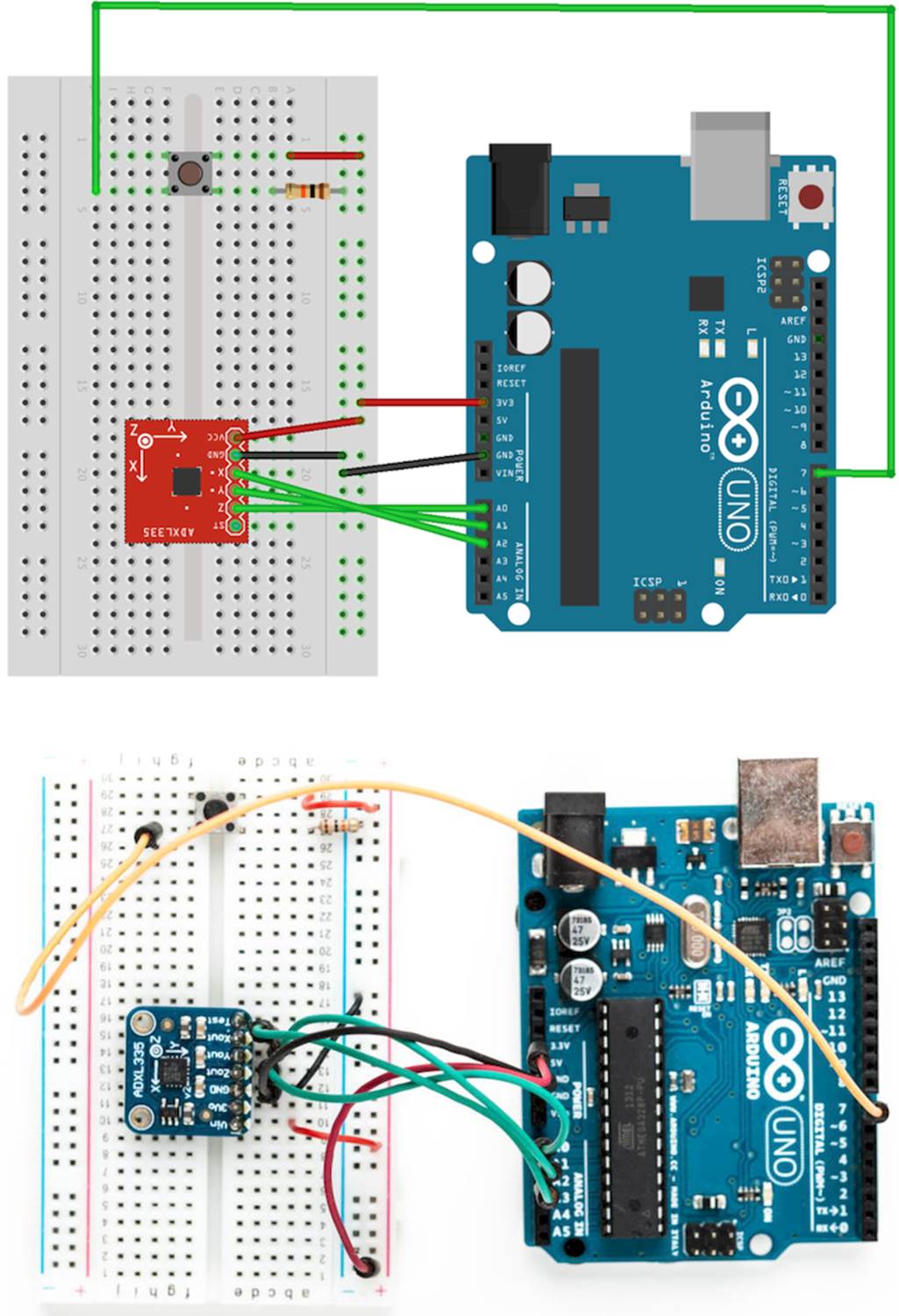
Figure 19. Game controller with accelerometer and pushbutton
That’s how it looks inside a typical modern game controller. We won’t build a fancy housing for the controller, but we still should think about ergonomics for a moment. Our current breadboard solution is rather fragile (see the following figure), and you cannot really wave around the board when it’s connected to the Arduino. Sooner or later you’ll disconnect some wires, and the controller will stop working.
To solve this problem, you could try to attach the breadboard to the Arduino using some rubber bands. That works, but it doesn’t look very pretty, and it’s still hard to handle.
A much better solution is to use an Arduino Proto Shield—a pluggable breadboard that lets you quickly build circuit prototypes. The breadboard is surrounded by the Arduino’s pins, so you no longer need long wires. Shields are a great way to enhance an Arduino’s capabilities, and you can get shields for many different purposes, such as adding Ethernet, sound, displays, and so on. The figure shows a bare Proto Shield and a shield containing our motion sensor.
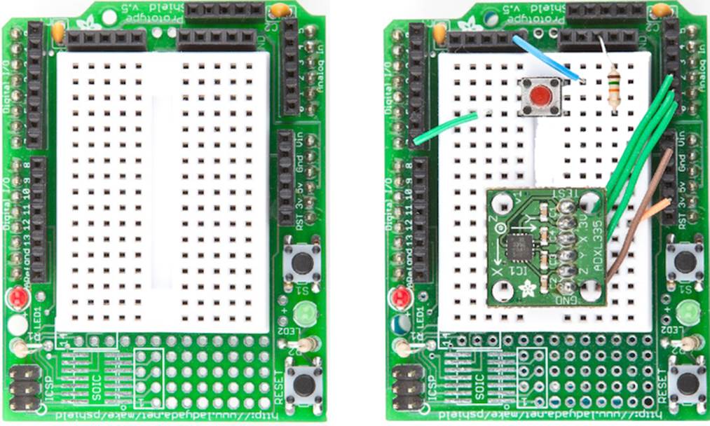
Figure 20. An empty Proto Shield (left), and one holding our game controller (right)
Now that the hardware is complete, we need a final version of the game controller software. It supports the button we’ve added, and it performs the anti-jittering we created in Finding and Polishing Edge Values:
|
MotionSensor/Controller/Controller.ino |
|
|
|
#include <Bounce2.h> |
|
|
const unsigned int BUTTON_PIN = 7; |
|
|
const unsigned int X_AXIS_PIN = A2; |
|
|
const unsigned int Y_AXIS_PIN = A1; |
|
|
const unsigned int Z_AXIS_PIN = A0; |
|
|
const unsigned int NUM_AXES = 3; |
|
|
const unsigned int PINS[NUM_AXES] = { |
|
|
X_AXIS_PIN, Y_AXIS_PIN, Z_AXIS_PIN |
|
|
}; |
|
|
|
|
|
const unsigned int BUFFER_SIZE = 16; |
|
|
const unsigned int BAUD_RATE = 38400; |
|
|
int buffer[NUM_AXES][BUFFER_SIZE]; |
|
|
int buffer_pos[NUM_AXES] = { 0 }; |
|
|
boolean button_pressed = false; |
|
|
|
|
|
Bounce button; |
|
|
|
|
|
void setup() { |
|
|
Serial.begin(BAUD_RATE); |
|
|
pinMode(BUTTON_PIN, INPUT); |
|
|
button.attach(BUTTON_PIN); |
|
|
button.interval(20); |
|
|
} |
|
|
|
|
|
int get_axis(const int axis) { |
|
|
delay(1); |
|
|
buffer[axis][buffer_pos[axis]] = analogRead(PINS[axis]); |
|
|
buffer_pos[axis] = (buffer_pos[axis] + 1) % BUFFER_SIZE; |
|
|
|
|
|
long sum = 0; |
|
|
for (unsigned int i = 0; i < BUFFER_SIZE; i++) |
|
|
sum += buffer[axis][i]; |
|
|
return round(sum / BUFFER_SIZE); |
|
|
} |
|
|
int get_x() { return get_axis(0); } |
|
|
int get_y() { return get_axis(1); } |
|
|
int get_z() { return get_axis(2); } |
|
|
|
|
|
void loop() { |
|
|
Serial.print(get_x()); |
|
|
Serial.print(" "); |
|
|
Serial.print(get_y()); |
|
|
Serial.print(" "); |
|
|
Serial.print(get_z()); |
|
|
Serial.print(" "); |
|
|
if (button.update()) { |
|
|
button_pressed = button.read() == HIGH; |
|
|
} |
|
|
Serial.println(button_pressed == HIGH ? "1" : "0"); |
|
|
delay(10); |
|
|
} |
As in Building a Dice Game, we use the Bounce class to debounce the button. The rest of the code is pretty much standard, and the only thing worth mentioning is that we use a 38,400 baud rate to transfer the controller data sufficiently fast.
Compile and upload the code, open the serial terminal, and play around with the controller. Move it, press the button sometimes, and it should output something like the following:
|
|
324 365 396 0 |
|
|
325 364 397 0 |
|
|
325 364 397 1 |
|
|
325 364 397 0 |
|
|
325 365 397 0 |
|
|
325 365 397 1 |
|
|
326 364 397 0 |
A homemade game controller is nice, and you can use it for many projects. For example, you could use it to control devices such as a robot, a marble maze, or something similar. Its original purpose is to control games, so we’ll build one in the next chapter.
More Projects
If you keep your eyes open, you’ll quickly find many more applications for accelerometers than you might imagine. Here’s a small collection of both commercial and free products:
· It’s a lot of fun to create a marble maze computer game and control it using the game controller we built in this chapter. How much more fun will it be to build a real marble maze?[64]
· In this chapter, we have measured only direct acceleration; that is, we usually have the accelerometer in our hand and move it. But you can also build many interesting projects that measure indirect acceleration, such as when you are driving a car.[65]
What If It Doesn’t Work?
All advice from What If It Doesn’t Work?, also applies to the project in this section. In addition, you should check whether you’ve soldered the pin header correctly to the breakout board. Use a magnifying glass and study every single solder joint carefully. Did you use enough solder? Did you use too much and connect two joints?
Exercises
· To get a better feeling for the data the accelerometer emits, you should write a few more sketches that focus on a particular axis. Write a sketch that outputs only the current value for the X-axis, for example. Turn an LED on when the X-axis value is above a predefined threshold value. Otherwise, turn it off.
Footnotes
|
[62] |
http://www.analog.com/en/sensors/inertial-sensors/adxl335/products/product.html |
|
[63] |
http://en.wikipedia.org/wiki/Circular_buffer |
|
[64] |
http://www.electronicsinfoline.com/New/Everything_Else/marble-maze-that-is-remote-controlled-using-an-accelerometer.html |
|
[65] |
http://www.dimensionengineering.com/appnotes/Gmeter/Gmeter.htm |
All materials on the site are licensed Creative Commons Attribution-Sharealike 3.0 Unported CC BY-SA 3.0 & GNU Free Documentation License (GFDL)
If you are the copyright holder of any material contained on our site and intend to remove it, please contact our site administrator for approval.
© 2016-2026 All site design rights belong to S.Y.A.