The Arduino Inventor's Guide (2017)
7 Tiny Desktop Greenhouse
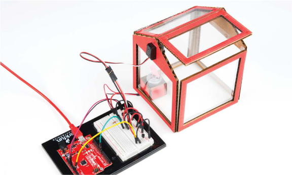
Greenhouses come in all shapes and sizes, from tiny indoor greenhouses made from plastic sheeting to large industrial greenhouses that span thousands of square feet. Not everyone wants a full-size greenhouse, though, so in this project you’ll build a smaller-scale model that can sit on your desk (Figure 7-1).
FIGURE 7-1: The Tiny Desktop Greenhouse
In a traditional greenhouse, the panes of transparent glass or plastic allow light energy in to heat up the interior of the greenhouse, and the greenhouse is sealed to trap that warm air inside, resulting in an overall increase in temperature. The danger, of course, is that a greenhouse might become too hot. To regulate temperature, many greenhouses have fans and autovents that open windows at the top of the greenhouse to ventilate when it gets too hot.
Your greenhouse will also have an autovent. You’ll build a greenhouse controller that will monitor the temperature, and if it gets too warm, a window will open and a fan will turn on.
THE GREENHOUSE EFFECT
Greenhouses are warm enough to grow veggies year round because they’re able to trap and store energy. Earth’s atmosphere works similar to a greenhouse. Heat from the sun is radiated by the earth and then reflected and captured by the atmosphere. This unique property is known as the greenhouse effect, and it’s responsible for keeping the temperature of our planet temperate and livable. Without it, the temperature of our planet would average near 0 degrees Fahrenheit (–18 degrees Celsius)!
Another common example of the greenhouse effect is a car in the middle of the summer. With the windows closed, the temperature inside the car can rise 20 to 30 degrees higher than the outside temperature. This is why you should never leave your pets in the car—especially in the summer!
MATERIALS TO GATHER
To lift the autovent, this project uses a servo motor similar to the one you used for the Balance Beam in Project 6. We’ll also introduce three new parts in this project: a small DC hobby motor for the fan, a transistor to control the motor, and a temperature sensor to detect the temperature inside the greenhouse.
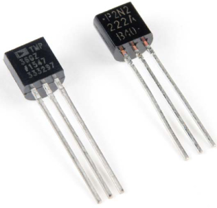
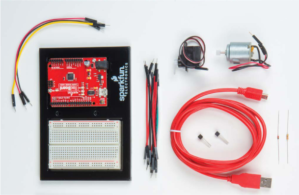
As you gather your parts, you’ll find that the transistor and the temperature sensor look very similar—they’re both small, threelegged devices that have a round, black plastic end with a flat edge (see Figure 7-2). To differentiate between them, tilt the flat edge against a light source, and you should see some printing; the temperature sensor should have the letters TMP marked on it. Gather your parts, shown in Figures 7-3 and 7-4, and let’s get started!
FIGURE 7-2: TMP36 temperature sensor (left) and 2N2222 transistor (right)
Electronic Parts
• One SparkFun RedBoard (DEV-13975), Arduino Uno (DEV-11021), or any other Arduino-compatible board
• One USB Mini-B cable (CAB-11301 or your board’s USB cable)
• One solderless breadboard (PRT-12002)
• One 330 Ω resistor (COM-08377, or COM-11507 for a pack of 20)
• One diode (COM-08588)
• One NPN transistor—2N2222 or BC337 (COM-13689)
• One TMP36 temperature sensor (SEN-10988)
• One hobby motor (ROB-11696)
NOTE
The parts marked with an asterisk (*) do not come with the standard SparkFun Inventor’s Kit but are available in the separate add-on kit.
• One submicro size servo motor (ROB-09065)
• Male-to-male jumper wires (PRT-11026)
• Male-to-female jumper wires (PRT-09140*)
FIGURE 7-3: Components for the Tiny Desktop Greenhouse
Other Materials and Tools
• Pencil (not shown)
• Craft knife
• Metal ruler
• Ruler
• Needle-nose pliers
• Wire cutters
• Glue (hot glue gun or craft glue)
• Masking tape (not shown)
• Cardboard (approximately one 11 × 17-inch piece or three 8.5 × 11-inch pieces)
• Enclosure template (see Figure 7-18 on page 208)
• 1 sheet (8.5 × 11 inches) transparency film (not shown)
• 1 medium-size paper clip (not shown)
FIGURE 7-4: Recommended tools and materials

NEW COMPONENTS
First, let’s take a look at the new components, starting with the temperature sensor.
TMP36 Temperature Sensor
You already know how to measure light levels. With this nifty sensor, you’ll be able to measure temperature as well. The TMP36 is one of the easiest temperature sensors to use. The sensor itself is encased in a small plastic shell shaped like a cylinder with a flat edge, and it has just three pins. (Remember to tilt the flat edge against the light to identify the letters TMP so you don’t mix it up with the transistor. If it says 2N2222 or anything else, it’s the wrong part.)
When properly connected to power, the TMP36 sensor will produce a voltage that is directly proportional to the temperature it senses. Similar to how you measured the light level in Project 5 or the position of the potentiometer in Project 6, you can use analogRead() to measure the voltage on this sensor. We’ll show you how to convert this voltage to a temperature reading in this project.
Standard Hobby Motor
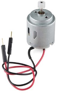
To move air through the greenhouse, you’ll build a fan using a small hobby motor, as shown in Figure 7-5. This is the simplest type of motor available. When you connect its two wires to a power source, the motor spins, and when you reverse the connections, the motor spins in the opposite direction. Unlike the servo motor that you used in Project 6, the hobby motor spins continuously. The hobby motor works with a voltage between 3V and 6V, so it’s perfect for Arduino projects.
FIGURE 7-5: Standard DC hobby motor
NPN Transistor
The invention of the transistor made it possible to create all kinds of digital devices. For example, the microcontroller on the Arduino is actually made up of millions of transistors. Transistors are part of a family of components called semiconductors. A semiconductor is a device that sometimes behaves like a conductor, allowing current to flow, and other times acts like an insulator, preventing current from flowing.
This project uses the transistor like a switch by boosting the Arduino’s amp output. The hobby motor uses about 200–300 mA of current, but the Arduino OUTPUT pins are only capable of sourcing about 40 mA of current. Using a simple transistor circuit, we’ll show you how to use the low-current Arduino pin to trigger the transistor to open or close, just like a switch.
TAKING A SYSTEMS APPROACH
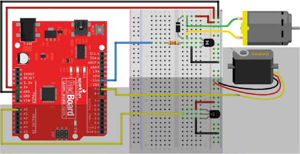
For the sake of organization, you’ll build this project as three separate parts, or subsystems. This technique, known as a systems approach, is used by engineers to separate a complex project into manageable sections that can each be built and tested individually. The main components of the three different parts are the temperature sensor, the servo motor (for the autovent), and the DC motor (for the fan). A schematic of the three parts is shown in Figure 7-6, and a wiring diagram of the compiled project is shown in Figure 7-7.
FIGURE 7-6: Schematic diagram of the circuit
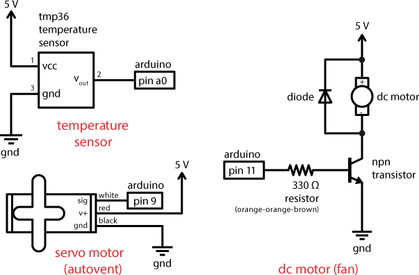
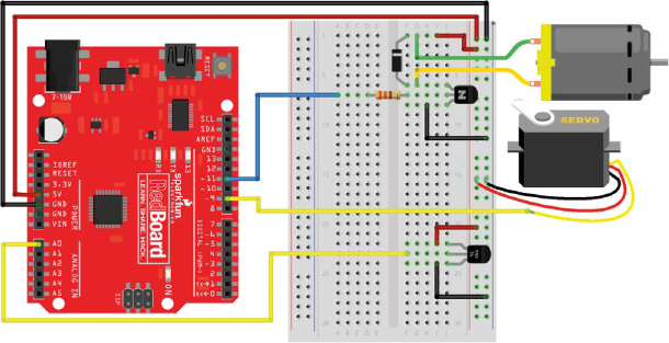
FIGURE 7-7: Wiring diagram of the circuit
BUILD THE TEMPERATURE MONITOR
First let’s take a look at the part of the greenhouse control system that will measure temperature. There are a lot of different temperature sensors out there. A few common types that you might encounter are thermistors, which change resistance based on temperature, and thermocouples, which output a really small voltage (less than 10 mV) and require an amplifier circuit to use. The TMP36 device is a third type of sensor that simply outputs a voltage calibrated to be 0.75 V at 25 degrees Celsius. The voltage then varies linearly based on the temperature of its surroundings. This means that as the temperature changes the voltage changes accordingly, as shown in Figure 7-8.
FIGURE 7-8: The linear temperature versus voltage response of the TMP36 sensor

Measure Temperature with the TMP36
The TMP36 is one of the easiest temperature sensors to use. The sensor is encased in a small plastic shell shaped like a cylinder with a flat edge and has just three pins.
As we mentioned earlier, the TMP36 looks very similar to the transistor, which also comes in the SparkFun Inventor’s Kit, so check the flat side of the component by tilting it at an angle under a light source, and look for the letters TMP. If it says 2N2222 or anything else, it’s the wrong part.
The TMP36 provides a voltage output directly related to the temperature in Celsius of its surroundings. Since you already know how to measure voltages using the analogRead() command, this sensor will be easy to use.
The outer pins are for ground and power connections, and the center pin is the voltage signal for the sensor. To use the TMP36, simply connect one pin to 5 V, one pin to ground, and the sensing pin to an Arduino analog pin to read the temperature. Pay attention to how you connect the sensor. With the flat edge facing to the left, the top pin should connect to 5 V and the bottom pin should connect to ground. At 25 degrees Celsius, the sensing pin will have a voltage reading of 0.750 V (750 mV). As the temperature changes, the voltage on this pin will change at a rate of 0.010 V (10 mV) per degree Celsius. Now, this might seem like a lot of math-speak, but we’ll show you how to use this information to get an actual temperature reading in your code and convert it to degrees Fahrenheit. But first, let’s wire it up.
Connect the Temperature Sensor
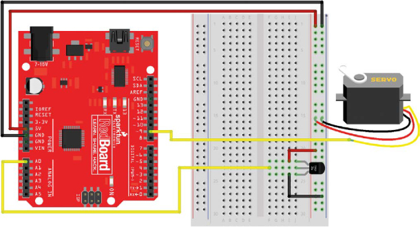
Figure 7-9 shows the temperature monitor circuit wired up on its own. Most of your components will be on the right side of the breadboard, so connect a jumper wire from 5 V and GND on the Arduino board directly to the power rails on the right side of the breadboard. Next, insert the TMP36 sensor into the lower portion of the breadboard, with the flat side of the sensor facing left, as shown in Figure 7-9.
FIGURE 7-9: Simplified wiring diagram showing only the temperature sensor
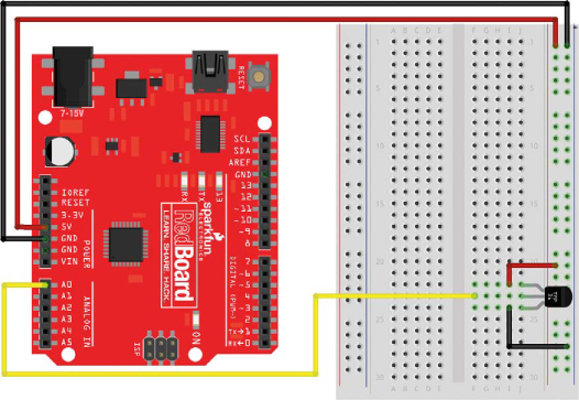
Next, use two short jumper wires to connect the TMP36 sensor’s top pin to 5 V and lower pin to ground, making sure the flat side is facing left. The middle pin is the output voltage of the sensor. Run a jumper wire from this pin to pin A0 on the Arduino board, and that’s it!
Now let’s take a look at a code example to see how to get temperature readings from this sensor.
Program the Temperature Sensor
The TMP36 sensor produces a voltage output relative to the ambient temperature. The datasheet for the TMP36 gives a couple of reference points for converting the voltage reading to a temperature: it shows that the voltage changes at a rate of 0.010 V per degree Celsius and that at 25 degrees Celsius, the sensor has a voltage of 0.750 V. Using this information, if you measure the output voltage from the sensor, you can convert this into a temperature reading in the code.
You may recall from Project 5 that the analogRead() function reads voltage as a whole number, with 1023 for an input of 5 V and 0 for 0 V. To make sense of this, you’ll need to convert that number to a voltage, then convert that voltage to degrees Celsius, and finally translate that value into Fahrenheit. To keep the code clean, you’ll first write a custom function to do the conversion from the raw analogRead() number to volts.
Create a Custom Conversion Function
Listing 7-1 shows an example of a custom function that will convert the raw analogRead() value and report back an answer that’s been converted to volts.
LISTING 7-1: Custom function volts() to convert from raw analog value to voltage
➊ float ➋volts(➌int rawValue)
{
➍ const float AREF = 5.0;
➎ float calculatedVolts;
➏ calculatedVolts = rawValue * AREF / 1023;
➐ return ➑calculatedVolts;
}
In Project 3, we showed you how to write your own custom functions to shorten your code and make the loop() easier to read. In those examples, the data type of the function was always set as void because the function didn’t report back a value. In this case, you’ll want the function to report back the conversion of analogRead() to volts, so you’ll have to specify a data type. Use the data type float ➊, because you’ll want this function to return the voltage with as many decimal places as possible for accuracy. Name the function volts ➋, to be as descriptive yet concise as possible, and then define the parameter(s) ➌ that you pass to this function. In this example, it is the raw value from analogRead().
The math needed to convert between raw analogRead() and voltage is pretty straightforward since, as we mentioned earlier, we already know that the analogRead() function returns 1023 for an input of 5 V and 0 for 0 V. This means that an analogRead() value of 1023 would be equal to 5 V. The custom volts() function uses this ratio to convert a raw analogRead() measurement to a voltage.
NOTE
It’s common practice to use ALL CAPS to designate objects or names that are constants.
First, declare a variable to use as a reference, named AREF ➍, and use this to define the reference voltage, which is 5.0 V. Because you’ll want to use it throughout the code, set it as a constant using the keyword const.
Next, you’ll define a variable to store the result of the conversion, named calculatedVolts ➎. Notice that the data type for this variable is set as a float as well. You’ll want to make sure that any math you perform is accurate beyond whole numbers. To calculate the voltage, simply multiply the rawCount by the ratio of AREF (5.0 V) to 1,023 ➏.
The return instruction ➐ is a command we haven’t used in the previous projects. When the sketch gets to the return instruction, it exits the custom volts() function and returns to the point in the code where it was called. When you put a value after the return instruction, the function returns and reports back that value. The return data type must match the data type of the function. For all the functions we’ve used to this point, we didn’t bother to include return, because those functions were defined as void data types and did not report back a value. Here, the return instruction is followed by the variable calculatedVolts ➑. This tells the sketch to report the value of calculatedVolts back to the point in the code where it was called.
Note that the return instruction can also be used with functions that have a void data type to instruct the sketch to leave the function and return. In that case, return is left blank with no value following it (see Listing 7-2).
LISTING 7-2: A custom function with a void data type and a return instruction
void blink()
{
digitalWrite(13, HIGH);
delay(500);
digitalWrite(13, LOW);
delay(500);
return;
}
Test the Function
Let’s test the new volts() function with an example sketch. Add a few lines in setup() and loop() to the code from Listing 7-1 to read the voltage on pin A0, and print it to the Serial Monitor. The complete code example is shown in Listing 7-3.
LISTING 7-3: Testing the analog-to-volts conversion
//Example sketch – reads analog input from A0 and prints the
//raw analog value and the voltage
int rawSensorValue;
float rawVolts;
void setup()
{
Serial.begin(9600); //initializes the serial communication
Serial.print("raw");
Serial.print("\t"); //tab character
Serial.print("volts");
Serial.println(); //new line character
}
void loop()
{
rawSensorValue = analogRead(A0); //read in sensor value
rawVolts = volts(rawSensorValue); //convert sensor value
//to volts
Serial.print(rawSensorValue); //print raw sensor value
Serial.print("\t");
Serial.print(rawVolts); //print raw voltage reading
Serial.println(); //new line character
}
/***********************************************************/
float volts(int rawCount)
{
float AREF = 5.0;
float calculatedVolts;
calculatedVolts = rawCount * AREF / 1023;
return calculatedVolts;
}
Connect your Arduino board to your computer with a USB cable, upload this example, and then open up the Serial Monitor. You should see text scroll up the screen like in Figure 7-10. According to this, an analog value of 156 is equal to a voltage of 0.76. You can check the output voltage with this calculation: 156 × (5.0 / 1,023) = 0.762 V. It’s always good when the math works out!
FIGURE 7-10: Serial Monitor output of raw sensor value and voltage
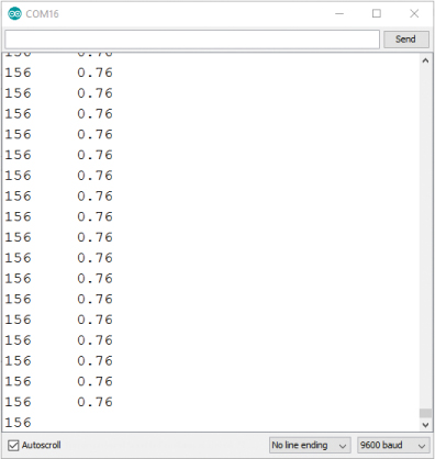
Without an additional delay() command in the loop(), the Arduino takes a sensor reading about 80–90 times per second and sends the information back to the computer. This is why you get a stream of readings rather than a single reading. If you want to slow down the rate at which the sketch prints the readings to the screen, simply add a delay(1000); at the end of the loop(), just after the last Serial.println();. This will slow the loop to a single reading per second so it’s not streaming as fast. You’ll do that later in the code.
There’s one more step to get the sketch to show the temperature rather than volts.
Convert Voltage to Temperature
Now you need a formula to convert the volts to temperature. You know that the voltage the TMP36 outputs varies linearly depending on the temperature it senses, meaning that as the temperature changes, the voltage changes proportionately. Therefore, to create a formula, you use the slope-intercept equation:
y = mx + b
This equation describes a line or, more generally, a relationship between two variables x and y, where m is the slope of the line describing the rate of change, and b is the y-intercept, showing where the line intercepts the y-axis. In this case, the two variables x and y are the voltage and temperature, respectively, and you’ll use the known variable x (volts) to calculate the unknown variable y (temperature).
As mentioned, the datasheet for the temperature sensor states that the voltage changes at a rate of 0.010 V per degree Celsius, or 1 V per 100 degrees Celsius. This rate is the slope of the line and so becomes m in the equation. If you plug in the variables, the equation looks like this:
![]()
The datasheet for the TMP36 also provides a reference point for mapping voltage to degrees Celsius: at 25 degrees Celsius, the sensor has a voltage of 0.750 V. Substitute these numbers into the equation to solve for the y-intercept b:
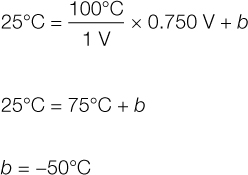
So now you have values for m and b. Here’s the final equation:
![]()
This is a technique that you can apply to any number of sensors that have a linear relationship with voltage. It’s also a nice reminder that math is important and useful. But, if none of that made any sense, don’t worry—all you need to know is that to find the temperature of the sensor, you simply plug the voltage reading into this equation.
Now, use this equation in the code to convert the rawVolts reading to a temperature. You’ll work from the example code in Listing 7-3 and add the new code in Listing 7-4 to show you the temperature reading from the sensor.
LISTING 7-4: Converting from volts to temperature
//Example sketch – calculates the temperature from the TMP36
//sensor and prints it to the Serial Monitor
int rawSensorValue;
float rawVolts;
➊ float tempC;
float tempF;
void setup()
{
Serial.begin(9600); //initializes the serial communication
Serial.print("raw");
Serial.print("\t"); //tab character
Serial.print("volts");
➋ Serial.print("\t");
Serial.print("degC");
Serial.print("\t");
Serial.print("degF");
Serial.println();
}
void loop()
{
rawSensorValue = analogRead(A0); //read in sensor value
rawVolts = volts(rawSensorValue); //convert sensor value
//to volts
➌ tempC = 100 * rawVolts – 50; //convert volts to deg. C
➍ tempF = 1.8 * tempC + 32; //convert deg. C to deg. F
--snip--
Serial.print(rawVolts); //print raw voltage reading
➎ Serial.print("\t");
Serial.print(tempC);
Serial.print("\t");
Serial.print(tempF);
Serial.println(); //new line character
➏ delay(1000);
}
/***********************************************************/
float volts(int rawCount)
--snip--
First, add two lines in the global namespace at the top to declare variables to store the temperature in degrees Celsius (tempC) and in degrees Fahrenheit (tempF) ➊. Next, add a few lines in the setup() to use appropriate column headings for the readings printed to the Serial Monitor, separated by a tab character, which is represented by the control character \t ➋. You can now use the slope-intercept equation to calculate the temperature in degrees Celsius ➌. You’ll also add one last line that converts the temperature from Celsius to Fahrenheit ➍.
And, for some additional feedback, add a few extra lines to Serial.print() to make sure you print the new variables ➎ to the Serial Monitor. Notice that the very last Serial.print() line is actually a Serial.println() command that inserts a newline character and moves the cursor to the next line. This will make sure each new reading starts on a new line. Finally, add the 1-second delay ➏ to slow down the loop so that the sensor is sampled only once per second and you have time to read the text.
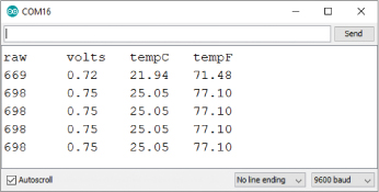
Upload the updated code to your Arduino, and open the Serial Monitor. You should see four columns of data scroll up the screen, as shown in Figure 7-11. As the new column headings denote, these figures represent raw data, voltage, temperature in degrees Celsius, and temperature in degrees Fahrenheit. If you squeeze the temperature sensor with your fingers, you should notice that the temperature increases. Congratulations, you have a working temperature monitor, the first big part of this project!
FIGURE 7-11: Serial Monitor displaying temperatures from the TMP36
BUILD THE SERVO MOTOR AUTOVENT
You’ll use a servo motor like the one you used in Project 6 to open and close a window on the greenhouse. A servo is a simple motor that uses three wires for the control signal (yellow or white), power (red), and ground (black) connections, as shown in Figure 7-12.
FIGURE 7-12: Adding the servo motor to the circuit
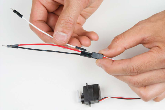
Most standard servos have a three-pin female connector. Connect three male-to-male jumper wires to these three pins to extend these connections, as shown in Figure 7-13. If possible, match the colors of your jumper wires to the leads on the servo connector. Then, connect the yellow (or white) signal wire to pin 9 on the Arduino board. Connect the red wire to 5 V and the black wire to GND on the right side of the breadboard.
FIGURE 7-13: Inserting male-to-male jumper wires to connect the servo to the breadboard
PROGRAM THE AUTOVENT
Add the servo code shown in Listing 7-5.
LISTING 7-5: Adding in the servo control
➊ #include<Servo.h>
➋ Servo myServo;
//Example sketch – calculates the temperature from the TMP36
//sensor and prints it to the Serial Monitor
int rawSensorValue;
float rawVolts;
float tempC;
float tempF;
➌ int setPoint = 85;
int returnPoint = 83;
void setup()
{
myServo.attach(➍9, 1000, 2000); //initializes myServo object
Serial.begin(9600); //initializes the serial communication
--snip--
}
void loop()
{
--snip--
Serial.println(); //new line character
➎ if(tempF > setPoint)
{
myServo.write(180);
}
else if(tempF < returnPoint)
{
myServo.write(0);
}
delay(1000);
}
/***********************************************************/
float volts(int rawCount)
--snip--
Remember from Project 6 that to use the servo you need to include the Servo library ➊ and create a servo object named myServo ➋. Next, create two variables ➌ to define the set points for the control system. These set points are the temperatures at which the window will automatically open and close. Notice that setPoint, which opens the window, is 2 degrees higher than returnPoint, which closes the window, giving you 2 degrees where the window will not be opening or closing. This control technique, referred to as hysteresis, is useful for systems where the temperature might fluctuate slightly and keeps the window from constantly opening and closing at the smallest temperature variation.
Finally, you need to initialize the servo by telling the Arduino that the servo is connected to pin 9 ➍. You might notice that this myServo.attach() command has two extra numbers, rather than the one number you used in Project 6. To understand why, take a look at “How Servos Really Work” on page 201.
Finally, for the control logic, you’ll use a nested if()–else if() control statement. Add the eight lines of code at ➎ just above the delay() to move the servo to a 180-degree position if the temperature is above 85 degrees Fahrenheit (the setPoint) and return the servo to the 0-degree position if the temperature drops below 83 degrees Fahrenheit (the returnPoint). This will open and close the autovent window.
Upload the updated code from Listing 7-5 to your Arduino, and open the Serial Monitor. Try it out by pinching the sensor between your fingers or cupping your hands around the sensor and blowing deeply to warm it above 85 degrees. Watch the Serial Monitor to see the temperature rise. As soon as it hits 85 degrees, you should hear the servo motor as it moves into position. Now, let the temperature sensor sit and cool down. As soon as it dips below the returnPoint, you should hear the servo motor again as it returns to the 0-degree position. Pretty neat, eh?
Now you’ll build the final component: the fan.
BUILD THE FAN MOTOR
The fan, which will move air around in the greenhouse, is going to spin via a small DC hobby motor—a standard cylindrical device with two wires and a center axle that spins when you apply voltage to the leads. The servo motor you’ve been using so far has gearing inside that allows it to move very precisely in a tightly defined range of motion. Recall that it has only about 180 degrees of motion. You’ll use a DC motor here, rather than the servo motor, because you’ll need the fan blade to spin continuously the entire time you apply power to it. This makes it perfect for a fan function. The DC motor you’ll use is designed to operate between 3 V and 6 V but draws around 200–300 mA when it’s spinning. The Arduino OUTPUT pins are capable of driving only about 40 mA of current, so to provide enough amps for the DC motor, you’ll build an extra circuit called a transistor amplifier circuit—more technically known as a common-emitter amplifier.
HOW SERVOS REALLY WORK
Servos are neat devices that move a motor to a specific position based on a signal from the microcontroller. A standard servo motor has a fixed range of motion of about 180 degrees.
All servo motors have three wires: a white (or sometimes yellow or orange) wire for receiving the signal, a red power wire, and a black ground wire. The signal is a unique pulse sent every 20 ms, or at a rate of 50 Hz. To encode a position, a microcontroller varies the width of the pulse to indicate the angle or position that the motor will turn to (see Project 5 for more details on pulse width modulation). For most standard servo motors, a 1,000-microsecond (1,000 μs) pulse indicates the 0-degree position, and a 2,000 μs pulse indicates the full 180-degree position, so a 1,500 μs pulse indicates the midpoint of the servo, or the 90-degree position.
The Arduino’s Servo.h library maps the pulse widths to the motor positions, but the library has a slightly different definition for the servo positions and pulse widths, using a 544 μs pulse for the 0-degree position and a 2,400 μs pulse for the 180-degree position. This allows the library to work with extended-range servos, but it is outside the limits of most standard servos. So, when you use a command like myServo.write(0); the motor receives a 544 μs pulse and will try moving beyond its own physical limits. If that happens, the motor will shake, buzz, and heat up because it’s just not able to move to a position that coincides with a 544 μs pulse.
To counteract this, you can set limits for the servo in the code. As in Project 6, use the command myServo.attach(9); to initialize the servo on pin 9 of the Arduino. You can also add parameters to set lower and upper pulse width limits for the motor, with myServo.attach(9, 1000, 2000);. With this initialization, the command myServo.write(0); will move the motor to its 0-degree angle position and it won’t shake, buzz, or heat up.
If you want to know more about how servos work, take a look at the tutorial on SparkFun at https://www.sparkfun.com/tutorials/283/.
A transistor has three legs: the collector (C), base (B), and emitter (E). Any current that goes into the base is amplified on the collector pin. The base is like a control for a door that allows current to move from the collector to the emitter. The more you push on the base, the wider the door opens, and more current can pass through from the collector to the emitter. The amazing thing about transistors is that you need apply only a small amount of current at the base to let a large amount of current flow from the collector to the emitter. If you provide too much current to the base, you can burn the transistor out, so in the same way you’ve used resistors to limit the current flowing through LEDs, you’ll use a 330 Ω resistor in this circuit to limit the current flowing to the base.
There are many different applications for transistors, such as amplifiers and other devices, but here you’re just going to use it like a controllable switch. Even though the Arduino pin can only supply a small amount of current, when you send a HIGH signal to the base of the transistor, the transistor turns “on.” This allows current to flow between the collector and the emitter. It essentially connects these pins together, like closing a switch.
The emitter side of the transistor is connected to the ground rail. Notice that one side of the motor is connected to the 5 V rail, and the other side of the motor is connected to the collector of the transistor. When the transistor is turned “on,” this connects the collector to the emitter of the transistor, closing the switch between the motor and ground and making it spin. Engineers call this “operating a transistor between cut-off and saturation mode.” Power for the motor is coming directly from the power rails. That means you can use the limited current provided by the Arduino OUTPUT pins to control devices requiring a much larger current flow.
You’ll build the transistor circuit on the top part of the breadboard, as shown in Figure 7-14.
FIGURE 7-14: Adding the fan-motor transistor control circuit
Find the transistor in your kit. As you can see from Figure 7-15, the transistor looks a lot like the temperature sensor, though if you look closely you should see 2N2222 or BC337 on the flat side of the casing. This is an NPN transistor, and it will act as the motor’s on/off switch that you control with the Arduino board.
FIGURE 7-15: NPN transistors used in this project—the 2N2222 (left) and the replacement part BC337 (right)
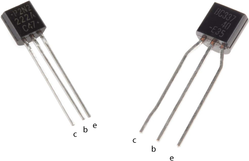
Hold the transistor so that the flat edge is facing to the left, and insert it into the top part of the breadboard with the top pin about six rows down, as shown in Figure 7-14. In this position, the top pin is the collector, the middle is the base, and the bottom is the emitter (Figure 7-15).
Connect a 330 Ω resistor to the base pin and stretch it across the ditch in the breadboard, as shown in Figure 7-14. Then, connect the other side of this resistor to pin 11 on your Arduino so that pin 11 connects to the base pin through the 330 Ω resistor. This is the low-current control signal from the Arduino that will switch the transistor on and off. When the transistor is switched on, current will flow through the motor, and it will spin.
Connect a small jumper wire from the emitter of the transistor (lower pin) to the ground rail. Lastly, connect one of the wires of the motor to the collector (top) pin of the transistor. The motor will spin either clockwise or counterclockwise depending on which wire you use, but in this case it doesn’t matter which way it spins, so you can choose either motor wire. Connect the other motor wire to the power rail, and then use a jumper wire to connect the power rail of the breadboard to 5 V on the Arduino. When a small current signal is detected on the base pin, the connection between the collector and the emitter is closed. This connects a path from 5 V through the motor to GND and completes a circuit path that will cause the motor to spin. Figure 7-16 shows the circuit for the motor.
FIGURE 7-16: Transistor circuit to drive the motor from an Arduino pin
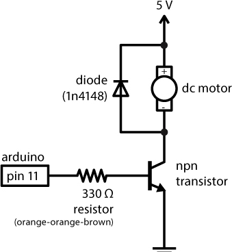
The last piece in this circuit is a protection diode, sometimes called a fly-back diode, and it protects the transistor from damage that may be caused by the motor. Inside a motor are a bunch of coils that create an electromagnet that pushes and pulls against permanent magnets in the motor—this is what causes the axle to spin. Coils are a really interesting component used in electronics. The magnetic field that they create is actually a form of stored energy, and when the circuit is turned off, this stored energy can rebound and cause large voltage spikes that will damage the transistor. The fly-back diode creates a path for this voltage spike to dissipate without going through the transistor. It’s sometimes also called a snubber circuit.
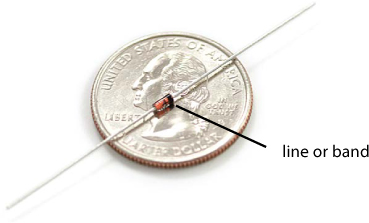
In order to wire this component in correctly, it is important to note that diodes are polarized, and the orientation makes a difference. The body of the diode has a line or band at one end of the body, as shown in Figure 7-17. Make sure that the side with the band is connected to the positive (5 V) side of the motor.
FIGURE 7-17: Fly-back diode used in the transistor circuit, with a quarter for size comparison
Add the diode to the motor, making sure that the side of the diode with the line is connected to the 5 V motor wire, as shown in the circuit diagram in Figure 7-16. Connect the other leg of the diode to the other wire of the DC motor—the one connected to the collector pin of the transistor. This means that the two legs of the diode share the same connections as the two wires of the motor. When two devices are wired up like this, we say they’re wired in parallel.
You should now have a complete circuit that has each of the three subcircuits in Figure 7-6. You’ll add a few more lines of code to control the motor.
Program the Fan Motor
The code for controlling the motor is very simple, just like the code you used to turn an LED on and off. Add the code in Listing 7-6 to your current sketch.
LISTING 7-6: Complete Tiny Desktop Greenhouse control code
#include<Servo.h>
Servo myServo;
--snip--
void setup()
{
➊ pinMode(11, OUTPUT);
myServo.attach(9, 1000, 2000);
Serial.begin(9600); //initializes the serial communication
--snip--
}
void loop()
{
--snip--
Serial.println(); //new line character
if(tempF > setPoint)
{
myServo.write(180);
➋ digitalWrite(11, HIGH); //turn the fan on
}
else if(tempF < returnPoint)
{
myServo.write(0);
➌ digitalWrite(11, LOW); //turn the fan off
}
delay(1000);
}
/***********************************************************/
float volts(int rawCount)
{
const float AREF = 5.0;
float calculatedVolts;
calculatedVolts = rawCount * AREF / 1023;
return calculatedVolts;
}
There are just a few new lines of code. The first is in the setup(). This sets pin 11, to which the motor is attached via the transistor, as an OUTPUT ➊. Next is the set of conditional if()–else if() blocks. Here, you add two commands to turn the motor on ➋ and off ➌. Remember that the motor will really be the greenhouse fan. With these few extra lines of code, the fan will turn on at the same time as the window opens, and it will turn off when the window closes.
After you’ve added these lines of code, upload this latest version to your Arduino. Open the Serial Monitor, and test it again. Try warming up the temperature sensor by squeezing it between your fingers or using your breath, and watch what happens. As soon as the temperature readings get to about 85 degrees Fahrenheit, the servo motor should move and the hobby motor should kick in. You might notice that as soon as the motor turns on, the temperature readings go all out of whack. There is a lot going on here, but we have a quick fix for it.
Isolate the Motor Effect
When the motor turns on, the voltage of the Arduino drops down to about 4.1–4.5 V because of the extra current load of the motor. You may see that as soon as the motor spins up, the temperature readings start changing sporadically, and the motor may continue to turn on and off several times before the temperature readings settle down. Earlier we said that when you use analogRead(), 1023 is equal to 5 V, but that’s only partially true. The full truth is that 1023 is equal to whatever the voltage from the source is, so if the source voltage drops to 4.1 V, 1023 is now equal to 4.1 V. This messes up the Arduino’s ability to take accurate measurements.
To rectify this, add two lines of code at the very beginning of the loop(), right after the first curly bracket, to tell the Arduino to turn off the motor before reading the temperature sensor:
digitalWrite(11, LOW); //turn off the motor before
//reading sensor
delay(1); //short 1 ms delay before
//reading sensor
Now the Arduino will turn the motor off for exactly 1 ms before reading the voltage on the temperature sensor. This isolates the voltage drop from the motor and the analogRead() without adding too much extra code.
After adding these two lines, upload the new sketch to your Arduino, and try heating up the sensor again. Now it should behave much more predictably. With the circuits built and the code working smoothly, it’s time to build the actual greenhouse structure.
BUILD THE TINY DESKTOP GREENHOUSE ENCLOSURE
We provide a template for the greenhouse enclosure we created using cardboard, but you could use anything you want. In fact, IKEA sells a great little greenhouse called the SOCKER that you could easily modify to work with this project.
For the Tiny Desktop Greenhouse, the finished dimensions are roughly 4.5 × 4.5 inches for the base and 6 inches at the tallest point. In the resources available at https://www.nostarch.com/arduinoinventor/, we have two template options: one is broken out into three sheets of 8.5 × 11-inch cardboard (shown in Figure 7-18), and the other is on a single sheet of cardboard measuring 11 × 17 inches.
FIGURE 7-18: Tiny Desktop Greenhouse cardboard enclosure template (not full size)
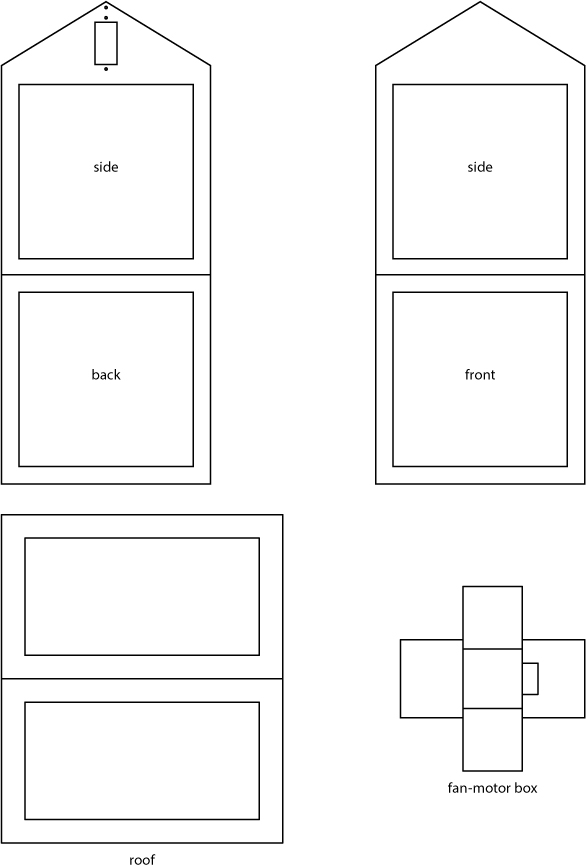
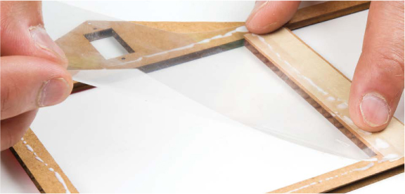
Carefully cut out the pieces of the template from the cardboard. There are four unique pieces: the pentagonal side pieces, the front/ back square walls, the roof window, and the fan-motor holder. Take one square side piece and one pentagonal front/back piece and lay them side by side, with the transparency side facing up. Use a narrow strip of masking tape to hold these two sides together, as shown in Figure 7-19. Repeat this process until you have all four of the side wall pieces attached, but don’t tape the last two walls together; leave the enclosure lying flat until you’ve added the windows.
FIGURE 7-19: Use a narrow strip of tape to hold the pieces together.

Now you need to cut six pieces of transparency film to be slightly larger than the opening in each of the wall pieces and the windows. For the template we provide, you will need four squares that measure 4.25 × 4.25 inches and two squares that measure 4.25 × 2.5 inches. You should be able to cut these six pieces out of a single sheet of transparency film; it’s a good idea to trace them on first to get the most out of the film. At this point, you only want to secure the windows for the side walls; you’ll add the roof windows at the very end. Using a bead of glue or small piece of tape, secure these windows to the inside of the greenhouse on the same side as the tape, as shown in Figure 7-20.
FIGURE 7-20: Carefully line up the transparency film window to adhere it to the cardboard.
Once those transparency panes are in place, run one more piece of tape along the last exposed edge, and connect it so that you have a square base and a structure that resembles a small greenhouse, as shown in Figure 7-21. The top and bottom of the greenhouse should still be open, and it may still feel a little unstable, but as soon as you add the roof, the entire structure will hold together.
FIGURE 7-21: Four sides of the greenhouse complete

Add the Autovent Window Servo
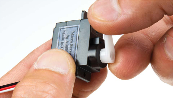
On our template, we made a small cutout for the servo motor as close as possible to the pivot point of the window, to maximize the amount the window opens when the servo horn moves. Disconnect the servo from your circuit, and attach a horn to the end of the servo if there isn’t one already there. We’d recommend using the single-sided horn, because it’s easier to tell where the servo is pointing. Gently rotate the servo clockwise with your fingers until it stops to set the motor at the 180-degree position. This is the position where the horn will be when the window is fully open. Remove and reposition the servo horn so that it is pointing up in the opposite direction from the wires that come out of the back of the servo, as shown in Figure 7-22.
FIGURE 7-22: Servo horn in the 180-degree position— rotated clockwise
Now feed the servo through the hole in the template from the inside of the greenhouse so that the wires are pointing down and the servo horn is on the inside pointing up (see Figure 7-23).
FIGURE 7-23: Placing the servo into the greenhouse
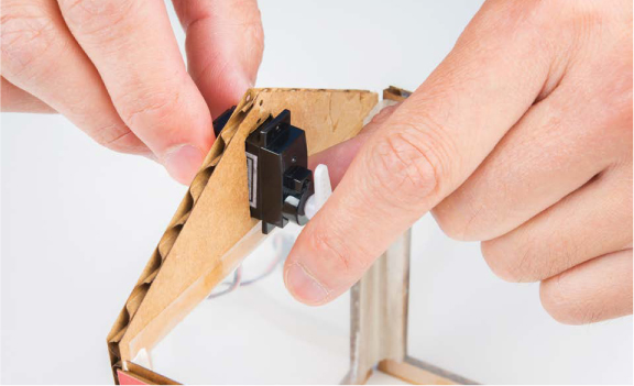
The tabs of the servo should sit flush with the cardboard. You can screw in the servo using the screws that come with it and the two small screw holes in our template, or use a few dabs of hot glue to secure it in place.
Create the Paper Clip Linkage
As in Project 6, you’ll need a linkage to connect the servo horn to the window. Take a medium-size paper clip and straighten out all but the small hook on the end. Now, grab a ruler and add a sharp 90-degree bend about 1 1/8 inches from the small hook end, pointing away from the hook, as shown in Figure 7-24.
FIGURE 7-24: Bending the paper clip linkage

Add the Roof
The roof piece is a rectangular piece of cardboard. Cut out the windows, and score the centerline of the roof, as shown in Figure 7-25. The scored edge will form a hinge for the window flap to open and close.
FIGURE 7-25: The roof piece

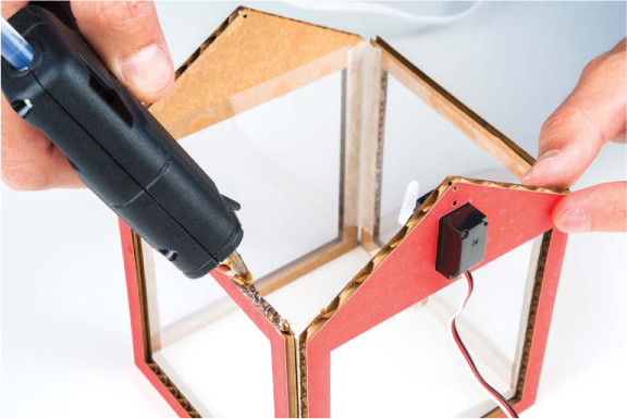
Position the greenhouse so that the servo is on the left side. One half of the roof will be secured down with glue, and the other half will form a window flap that opens and closes. Using a small bead of hot glue, attach one half of the roof structure to the greenhouse. Only glue down three edges of the roof (that is, one half of the six edges) so that there’s still a flap that can open. Make sure that the side that opens coincides with the side that the servo horn moves against, as shown in Figure 7-26.
FIGURE 7-26: Gluing in the roof. Be sure to only glue one half of the roof so that the other side can open.
Hook the paper clip linkage around the last hole in the servo horn, as shown in Figure 7-27, with the rounded hook attached to the servo. Make sure that the opposing bend is pointing back toward the servo motor. This will hook into the frame of the roof piece.
FIGURE 7-27: Servo horn and paper clip linkage
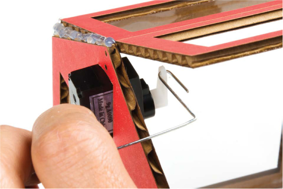
Keeping the window flap open, rotate the paper clip until you can insert it into the side of the frame through the cardboard itself. If the paper clip isn’t long enough to reach, you can either rebend it or reposition the servo horn at an angle rotated slightly higher to extend the reach of the linkage. It may be helpful to lift the greenhouse structure and reposition the servo horn from underneath. Once you’ve positioned the servo horn so it will reach, insert the end of the paper clip into the side of the window frame, as shown in Figure 7-28.
FIGURE 7-28: Servo arm linkage connected to the window flap
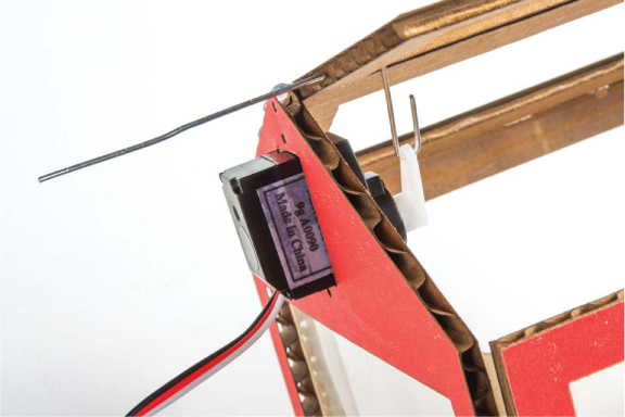
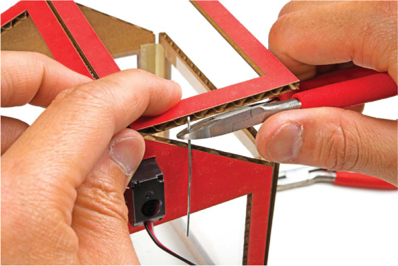
Bend the portion of the paper clip that protrudes from the other side to create a hook so that the linkage does not fall out (see Figure 7-29), and cut the remaining end off. Now carefully move the servo back and forth; you should be able to open and close the lid of your greenhouse!
FIGURE 7-29: Bending the hook in the servo linkage
With the mechanism complete, you can glue or tape the transparency windows for the top of the greenhouse. A small dab of glue on the four corners will be just enough to hold the window pane down. The window panes should go on the outside of the greenhouse roof to allow room for the linkage to open and close the lid. Next, you’ll build a box to hold the motor and fan.
Build the Fan-Motor Box
The motor will serve as a fan to move air around when the greenhouse gets too warm. To prevent the motor from moving as it spins and vibrates, we designed a small cardboard box to hold it in. The template has a design for a five-sided box with a small hole to allow the motor wires to come through, shown in Figure 7-30.
Cut out this template from a piece of cardboard, and carefully score the dashed lines so that it can fold up into a box. Using either tape or hot glue, secure the four sides of the box so that it will hold the motor snugly (see Figure 7-31).
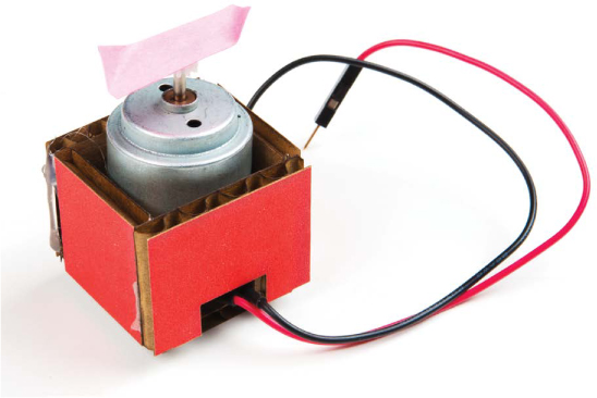
To build a fan blade, you’ll glue a small piece of cardstock onto the end of the motor. Cut the fan blade so that it is no more than 1.25 inches wide. To help the fan move more air, fold the edges of the cardstock as shown in Figure 7-32.
FIGURE 7-30: The fan-motor box

FIGURE 7-31: Completely assembled motor box with the motor inside
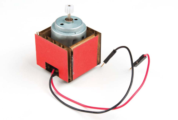
FIGURE 7-32: Final fan blade

This will ensure that the fan doesn’t hit the plant or anything else inside the tiny greenhouse. Using a small dab of hot glue, attach the fan blade to the motor as shown in Figures 7-33 and 7-34.
FIGURE 7-33: Securing the fan blade to the motor
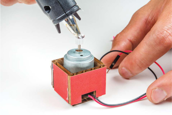
FIGURE 7-34: Fan-motor assembly complete
Connect It Up
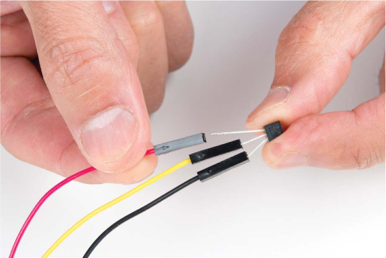
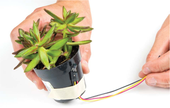
Now you have all of the pieces you need for your Tiny Desktop Greenhouse, so it’s time to install the electronics. Remove the temperature sensor from the breadboard, and use three male-to-female jumper wires to extend the connections of the sensor, as shown in Figure 7-35. Pay attention to which wires you move, and connect them up again using the extended wires. When you hold the flat side of the temperature sensor facing you with the pins to the left, the top pin is power, the middle pin is the signal, and the bottom pin is ground. We used red, yellow, and black wires to show the power, signal, and ground connections, respectively.
FIGURE 7-35: Extending the temperature sensor with male-to-female jumper wires
You’ll need to place the temperature sensor inside the greenhouse. Use a piece of masking tape to secure the temperature sensor directly to the plant before sticking it inside your new greenhouse, as shown in Figure 7-36. You can now feed the wires out under one side of the greenhouse, or you could also make a small hole to feed the wires through.
FIGURE 7-36: Secure the temperature sensor directly to your plant
Similarly, move the fan-motor assembly so that it sits near the corner of the greenhouse. The motor wires should be long enough to reach the breadboard without extensions, but if you need to, you can add extra male-to-female extension wires to make wiring easier.
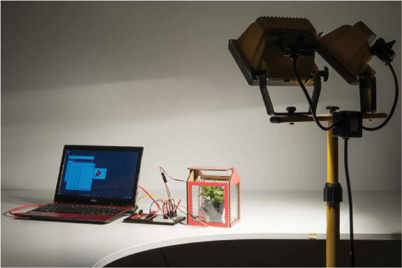
Now, you should still have enough room for a small plant to rest comfortably in this new cozy habitat. It’s time to get your new exotic house plant and put it inside your brand new greenhouse! To test out how effectively our autovent system regulated the temperature, we created our own indoor sun with some really big floodlights to heat the air.
Figure 7-37 shows one of our tests on the Tiny Desktop Greenhouse.
FIGURE 7-37: Testing a Tiny Desktop Greenhouse
GOING FURTHER
There are a lot of opportunities to take this project to the next level.
Hack
At the moment, your greenhouse is pretty darn small. To make space for more plants, find a large cardboard box like the ones used for copy paper. Cut some windows in it, line them with transparency film, and move the electronics into this bigger and better greenhouse. Or, take a look at the plastic greenhouses they have over at IKEA. Where can you mount the servo motor so that you can open and close the window on this greenhouse?
Modify
The current set point is 85 degrees Fahrenheit, and although that was a good temperature for us to test because we could easily increase it with our own body heat, it’s actually still pretty low for most plants. Look up the ideal growing temperature for your plant, and modify your code to use this new set point.
You can also modify how often the greenhouse samples the temperature with the delay. A delay of 1 second is pretty short. If your temperatures swing at all, the lid will be opening and closing every few seconds. This can quickly become annoying. Change this delay to something like 5 minutes, which would be 30,000 ms.
All materials on the site are licensed Creative Commons Attribution-Sharealike 3.0 Unported CC BY-SA 3.0 & GNU Free Documentation License (GFDL)
If you are the copyright holder of any material contained on our site and intend to remove it, please contact our site administrator for approval.
© 2016-2026 All site design rights belong to S.Y.A.