Professional Embedded ARM Development (2014)
Part I. ARM Systems and Development
Chapter 4. ARM Assembly Language
WHAT’S IN THIS CHAPTER?
Introduction to ARM assembly
Use of assembly
Understanding condition codes
Understanding addressing modes
Understanding your first ARM assembly program
Assembly language is the most basic programming language available for any processor. It is a collection of commands, or instructions, that the processor can execute. A program is a list of instructions in a specific order telling the computer what to do. Just like a calculator, you can tell a processor to take a number, to multiply it by 2, and to give you the answer. However, you need to supply some more information; you need to tell the processor where to get the number and what to do with it afterward.
INTRODUCTION TO ASSEMBLY LANGUAGE
A processor runs machine code, and machine code can be specific from one processor to another. Machine code written for a 6502 cannot, and will not, run on a 68000. Machine code is a list of numbers that make no sense whatsoever to (most) humans. To make the programmer’s life a little more bearable, Assembly language was invented. Assembly language consists of words and numbers, and although it isn’t as easy to understand as the English language, it is much easier to understand than reading numbers or punch cards.
Assembly language enables programmers to write computer programs, telling the processor exactly what it must do.
TALKING TO A COMPUTER
Talking to a computer isn’t as easy as you would think. Hollywood has made a good job of making you think that computers are highly intelligent, but they aren’t. A computer can follow instructions, no matter how badly written they are. To write good instructions, you need to know exactly how a computer works. You learned about the memory and about input and output, but now here’s a little more about the processor and what it contains.
All processors use registers, internal memory used for specific reasons. ARM processors have 16 registers, named r0 to r15. But what exactly is a register?
A register is, put simply, a memory location that can contain one number. Remember when you were at school, and you had a written test in front of you. “How much is 5 times 3?” Instinctively, today, you would write down 15. The habit over the years makes you forget about what actually goes on, but try to think of it through a child’s perspective. This is an operation that he does not immediately know the answer to, so he takes it step by step. Take the first number, 5, and put it into your memory. Then take the next number, 3, and put that into your memory, too. Then do the operation. Now that you have the answer, write that down onto the paper. This is illustrated in Figure 4-1.
FIGURE 4-1: An example of mental calculation
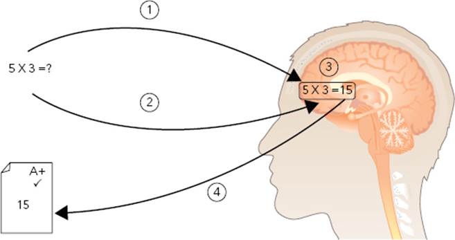
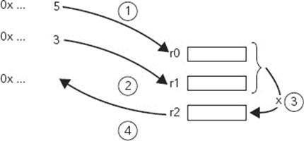
A processor does the same thing. An ARM processor cannot do mathematical operations straight to and from memory, only registers. In this example, take the number 5 and load it into a register, let’s say r0. Now, take the number 3, and load it into r1. Next, issue an instruction to multiply the value stored in r0 by the value stored in r1, and put the result in r2. Finally, write the value stored in r2 into the system memory. This is illustrated in Figure 4-2.
FIGURE 4-2: A calculation on an ARM processor
The question remains: Why do you need registers? Couldn’t you do your operations directly into memory? The reason is simple, speed. By designing this functionality into the processor, it also makes the processor simpler, and reduces the amount of transistors required. This is one of the key factors in Reduced Instruction Set Computer processors.
WHY LEARN ASSEMBLY?
Assembly has been around since, quite literally, the beginning of processors. It is the lowest-level instruction set that a processor can use, and each processor has its own instruction set. Initially, everyone had to write computer programs in assembly. In today’s world you have a choice of more than 100 programming languages, each with its strong points and weak points. Most low-level development today is done in C, a language that can be easily ported from one processor to another. It is easier to read than assembly and has many advantages over assembly. There is also another reason – portability. As seen previously, an assembly program written for one type of processor will not function for another type. Not all processors have the same instructions, or the same way of handling data. It is the C compiler’s job to convert the C files into machine code for the correct processor. This might not seem important, since you may already know exactly what processor you will be using, but the C compiler knows about some of the optional features of the processor and can create optimized programs. Also, an external library might be designed to be used on a wide variety of processors, not just one specific processor.
So why would anyone need to learn assembly? Although languages such as C might present huge advantages, what you see is most certainly not what you get. It doesn’t matter what language you choose – C, Python, Java, etc. – in the end, the only language a processor can use is assembly. When writing a program in C, the code is eventually compiled into assembly language. Although most programmers might not be concerned by assembly, embedded engineers will, sooner or later, be confronted by assembly code.
Embedded systems have two constraints that might not be as important for larger computer systems: speed, and size. Embedded systems often have to be as fast as possible and are usually heavily limited in terms of memory.
Speed
The Airbus A320 relies on a 68000 processor for the ELAC, the Elevator and Aileron Control. The 68000 was introduced in 1979, and although it is considered to be an “old” processor, it is also one of the most reliable. It is for this reason that it is used in mission-critical systems, but it comes at a price. It is not one of the fastest processors available, so all instructions must be carefully written and optimized to make sure that the chip runs as fast as possible.
This brings a question, one that sometimes surprises newcomers. Doesn’t the compiler always create the most optimized code possible? The answer is no. They normally do a good job, but once in a while, they surprise you, or they won’t quite understand exactly what it is you want to do. They can never be any better than you are. Imagine a shopping list. You have friends visiting, and you want to cook something for them, such as Chicken Basquaise. So, you start your list; you need a pound of tomatoes, a chicken (or six chicken breasts), four red peppers, three onions, some white wine, some thyme, and some basmati rice. And off you go with your recipe list. The list contains everything you need. (Although you might add a few more ingredients here and there.) You have several choices as to what to do. You can get the ingredients as they appear on the list; start with the tomatoes, then get the chicken, and then go back to where the tomatoes were to get the peppers. Depending on the size of the supermarket, you can lose a lot of time. If you plan ahead, you could have at least grouped everything together. So this time, get the tomatoes, the red peppers, and the onions because they are in the same place. You don’t need to backtrack to get something that was close to you. You have just optimized. The result is exactly the same, but it is quicker. But can you do anything else? Yes, you can; you can go even further. In the supermarket close by, there are two entries. Thinking cleverly about this, start with the tomatoes because they are close to the south entry. A few feet later, you can find the red peppers. From there, get the chicken. Going right, two lanes later, you find the white wine. Then continue your list getting the ingredients in the order that they appear while making your way to the north entry. Making the list would probably take much longer, but you now have the optimal list, one that takes you the shortest time possible. How much time would you spend on your shopping list? And how much time would you save with your new optimized path? Well, that depends. You won’t spend an hour making a list if it saves only 8 minutes in the supermarket. If it can save 5 minutes, you will probably take 2 minutes to group the ingredients together. But what would happen if you had lots of friends and invited them over every weekend? Assuming that your friends wouldn’t mind eating only Basquaise chicken, you could theoretically save 8 minutes each time, about 50 times a year? That 2-hour shopping list would have saved you a total of 6 hours in the supermarket.
Although this example is ridiculous, it serves a point. On an embedded system, there are parts of the program that you will run thousands, if not millions of times. A few milliseconds here and there could save you a lot of time later. It could also mean using a cheaper chip because you might not need the expensive 40MHz version since you were clever and managed to optimize everything so that the 20-MHz version would work.
Code from C and C++ can be compiled into machine language, and although the compilers normally do a good job, sometimes you have to write heavily optimized routines in assembly, or correct what the compiler is outputting. Also, some start-up routines cannot be written in C; to activate memory controllers or cache systems, you have to write some assembly code.
Rear Admiral Grace Hopper was one of the first programmers of the Harvard Mark I computer, an electro-mechanical computer built in 1944. She became obsessed with well-written code and often lectured on the subject. She became famous for her representation of a microsecond and a nanosecond, producing lengths of wire corresponding to the maximum distance that light could travel in that amount of time. When talking about a nanosecond, she produced a series of wires that were 11.8 inches long (29.97 cm). In comparison, she produced a wire corresponding to the maximum distance traveled by light in one microsecond, a total of 984 feet long (just under 300 meters). Producing a wire that long, she went on to say: “Here’s a microsecond. Nine hundred and eighty-four feet. I sometimes think we ought to hang one over every programmer’s desk, or around their neck, so they know what they’re throwing away when they throw away a microsecond.”
Size
A while ago, I was working on a bootloader for a mobile phone. A bootloader is the first piece of code that is run on an embedded system; its job was to test to see if a program existed on the telephone. If such a program existed, there were cryptography checks to make sure that this was an official program. If the tests failed, or if no program was present, it put itself into a special mode, enabling a technician to download a new firmware via USB. To do that, we had to initialize the DDR memory, activate the different caches available on our CPU (in this case, an ARM926EJ-S), and activate the MMU. We also had to protect the bootloader; its job was to flash a new firmware but not give access to protected systems (the baseband, or confidential user information). We had to do all this in 16 Kb of NAND flash memories. Of course, in the beginning, there were huge ambitions; we could add a nice logo, a smooth menu interface, a diagnostics check, and so on. The list went on. When we released our initial binary, we were four times over the size limit. With a little optimization, we were three times over the limit. By getting rid of the fancy image, and the fancy menu, we were at 32 Kb. We started optimizing our C code, getting rid of a few functions here and there, and we came up with a binary just above 17 Kb. Several people tried to modify the C code, but we just couldn’t get it below 16 Kb; we had to dig deeper, so we looked at the assembly code.
We soon realized that there were a few things that we could do, but we would shave off only a few bytes here and there. By changing how the program jumped to different functions, by modifying a few loops, and by repeating the process, we slowly made our way down to 16 Kb. In the end, we not only made the 16 Kb, but we also reduced the code further, allowing a few routines to be added.
Code compilers normally do a good job, but they aren’t perfect. Sometimes they need a little bit of help from the developer.
Fun!
Writing in assembly can even be fun. No, seriously! In 1984, a new game called Core War was developed. It simulated the inside of a small computer. Two programs are inserted at random locations into the virtual memory, and in turn, each program executes one instruction. The aim of the game was to overwrite the other program and to control the machine.
In Core War, a dedicated language was used, called Redcode. However, it was rapidly “ported” to other systems, including ARM-based systems, as a fun way to learn programming. Battles were waged for entire evenings, with people testing their code. It wasn’t that simple. Code couldn’t be too large; otherwise, it might be damaged by the adversary. Different strategies were developed, and soon several “classes” became known, some often highly specialized in defeating another specific class. It was also an excellent way of teaching people what would happen if code was badly written.
Compilers Aren’t Perfect
From time to time, you will be faced with a situation in which your product does not function as it should, but for some reason the code looks perfectly good.
On one occasion, I was confronted by a problem on an embedded system. We needed to read in a number from a sensor and to do a few calculations on that number to output a chart. There were three ways we could access the information, but one of them wouldn’t work. We got a completely incoherent value, every time. The other two worked fine, so we knew that the sensor was working correctly, but these two ways were not available everywhere in our code. In one particular place, we had no choice but to use the third way. It didn’t take us long to use a debugger, a Lauterbach Trace32. We were confident that we could find the problem immediately, using step by step, but this just confused us more. The code was perfect, everything looked fine, but on one particular instruction, the output was meaningless. We had no choice but to dig deeper and look at the assembly code. It didn’t take us long to realize that there was an alignment problem; instead of reading in one 32-bit integer from memory, the processor had to read in 4 bytes and do a quick calculation on all 4 to create a 32-bit integer, but the compiler failed to do this correctly, resulting in a corrupt value. Realigning the data fixed the problem immediately.
On another occasion, a basic routine didn’t work as we wanted it to. We needed to loop 16 times and do a calculation each time. For some reason, we never managed to. The code was simple:
for (i = 0; i < 16; i++)
DoAction();
Except it didn’t work as intended. We checked: i was an integer, correctly defined. It worked before and afterward. Bringing up the assembly listing, we saw that it did indeed loop, but the variable was never initialized; the value of i was never set to 0. To this day, we use the same code, but just before, we set i to zero, and there is a comment explaining that the line must never be removed.
Understanding Computer Science through Assembly
Computers are a mystery to most people and embedded systems even more so. When talking to engineers, most understand the system, some understand what happens on lower layers, but today, relatively few understand what actually happens deep inside the mainboard. A good way to learn about what happens deep inside a CPU is to learn assembly. With Assembly language, you are at the lowest level possible and can understand what happens when you run a program.
Shouldn’t You Just Write in Assembly?
Sooner or later, everyone asks, “Shouldn’t I just write in Assembly? It’s fast! It’s lightweight!” Yes, but don’t. There are very, very few projects that are written in assembly. Your time is valuable; don’t start in assembly. Writing in C is much faster, and the compilers normally do an excellent job. If they don’t, or if you need a routine that is highly optimized, carry on writing the code in C, and then look at what the compiler generates. You can save time doing this, and even if the end result is not 100 percent what you expect, the compiler probably does all the structuring that you want.
Writing in assembly does not automatically mean fast and elegant code, on the contrary. Just like with any language, it all depends on the quality of what you write; it is possible to make something in assembly that is slower than in C. Assembly is useful to know; you may face it several times in a single project, but with years of development, higher-level languages do make more sense.
Most experts agree; start by completing a project before looking to optimize it. Numerous tools exist to analyze code, and see what portions are called, and which portions take the most time to execute. It is always possible to return to some code and try to optimize, but working with highly optimized code from the start can be a nightmare. When you know where your CPU spends most of its time, then you can replace some parts with assembly.
USES OF ASSEMBLY
Few projects will be written entirely in assembly; using higher-level languages such as C just makes sense. They are quicker to develop and easier to maintain, and compilers do a good job in translating C to assembly. So, what exactly are the uses of assembly?
There are several reasons why assembly is still used, from bootloading the first steps of a project all the way to debugging a finished project.
Writing Bootloaders
You’ve almost certainly seen a lot of programs written in C, but the first instructions of a bootloader are generally written in assembly. Some routines, like setting up the vector tables, cache, and interrupt handling cannot easily be done in C. Also, some bootloaders need highly specialized code, either for size or speed, where assembly is needed.
Much of the processor’s low-level configuration cannot be done in C; changing registers in a coprocessor requires assembly, and it cannot be done by writing memory. The first instructions of the Linux kernel are in assembly for this reason.
Reverse Engineering
Reverse engineering has been used from the beginning of the computer era, for good and for bad reasons. Sometimes it is necessary to see how a peripheral is initialized, and only the assembly code is available. Many drivers have been created this way, supporting devices made by companies that no longer exist, where no source code is available.
The Gaming Industry, Building a Better Mousetrap
As soon as the first computers became reasonably small, games have been available. People have always been fascinated with computer games, and today it is one of the biggest industries. The first medium for games was the good old cassette; an analog media that the new generation will probably never know. A standard tape player could be plugged into a computer to load programs directly. After a few minutes of watching colored bars on a screen, you were ready to play! And ever since the first games, software piracy has existed.
Copying tapes was ridiculously easy. High-end tape players could simply copy the audio from one tape to another, possibly degrading quality, but still allowing almost anyone to play a copy.
Game developers fought back. New systems were invented; questions were asked during the game. Upon reaching the doors to the city, a guard would ask, “What is the second word of the third paragraph on page 20 of your game manual?” Giving a wrong answer would mean never allowing you into the city, effectively stopping your game. Although it was possible to photocopy a manual, it did make things considerably more difficult for software pirates and also for people who actually did own the game.
Disk protection was also added. By directly modifying data on a disk’s surface, a game could easily detect if the disk was an original. The disk copy program from the operating system would refuse to copy a sector that it thought to be in error, stopping disk copying. Again, systems were made that enabled disk copying, but it stopped most cases.
Hardware dongles were considered to be the “ultimate” protection. An application would look at the hardware on the computer, most often on the serial port, and ask a question. The dongle would provide an answer, and the program was effectively authenticated. Copying a dongle was very, very complicated. Most often, custom hardware chips were used, and the cost of creating a copy vastly outweighed the cost of a software license.
Software pirates changed their strategy. Instead of using hardware to make copies, they turned to software. Buried deep inside the application was a few lines of code of particular interest. Somewhere in the code, the application would look at something particular, receive an answer, compare that answer, and then either continue if the answer was correct, or stop if the answer was wrong. It didn’t matter what language the program was initially written in; it all came down to assembly. By reading the assembly code, and finding out where the program looked for this particular piece of information, pirates could either force the answer to always be correct, or skip the question completely. Although this might sound easy, a program can be millions of lines of code long, and the portion that checks for copy protection might be as little as 10 lines. Also, the original code might have comments explaining what the developer was doing, or variables with useful and meaningful names, but not in assembly. There were certain techniques for helping pirates; serial ports mostly use the same address, so it was possible to analyze code looking for a specific address and then find out which of the results looked like the copy protection.
Software developers fought back. Copy protection was added into several parts of the code, making reverse engineering more difficult. Secondary routines checked to see if the primary routines hadn’t been changed. False copy protection routines were added as a lure. Techniques became more and more sophisticated, but still someone came up with something to disable the copy protection features. Some do it for Internet fame, some do it to play the latest games, but some do it simply as a challenge.
Optimization
Most compilers do a good job at taking C files and converting them to assembly instructions. With a few command-line options, compilers can be told to optimize for speed or for size (or a mixture of both), but there are times when a compiler cannot correctly do its job and delivers functional code, but far from optimized.
ARM’s weakness is division. More recent Cortex-A cores can do integer division, but previous cores had to do division in software – something that could take a lot of cycles to complete. When a function does one division, it isn’t always necessary to optimize, but when a function does repeated calculations, sometimes several thousand times, it is often worthwhile to spend a little bit of extra time to see what can be done. Maybe a routine will divide only by 10, in which case a new function can be created, with tailor-made assembly instructions to get the job done as fast as possible.
ARM ASSEMBLY LANGUAGE
The ARM Assembly language is a well-designed language that, despite first impressions, can actually be easy to read. Where possible, it has been designed so that it can be easily read by a human, for example:
ADD r0, r1, r2
This instruction can look a little frightening at first, but it is easy. ADD is the shorthand for a mathematical addition. The three subsequent registers define the operation, but in what order? Well, a human would write the operation as r0 = r1 + r2, and that is exactly what is written here; ADD result = value 1 + value 2. The processor adds the value contained inside r1 and the value contained inside r2, and puts the result into r0.
Layout
An assembly program source file is a text file and consists of a sequence of statements, one per line. Each statement has the following format:
label: instruction ;comment
Each of the components is optional.
Label – A convenient way to refer to a memory location. The label can be used for branch instructions. The name can consist of alphanumeric characters, the underscore, and the dollar sign.
Comment – All characters after an @ are considered comments and are there only to make the source code clearer.
Instruction – Either an ARM instruction or an assembler directive
.text
start:
MOV r1, #20 ;Puts the value 20 into register r1
MOV r2, #22 ;Puts the value 22 into register r2 ADD r0, r1, r2 ;Adds r1 and
r2, r0 now contains 42
end:
b end ;Infinite loop, always jump back to "end"
Instruction Format
This is the standard layout used in ARM assembly:
<op>{cond}{flags} Rd, Rn, Operand2
For example, the following code is used to add two registers together:
ADD R0, R1, R2
<op> – Three-letter mnemonic, called the operand
{cond} – Optional two-letter condition code
{flags} – Optional additional flag
Rd – Destination register
Rn – First register
Operand2 – Second register or second operand
Condition Codes
You can add a two-letter condition code to the end of the mnemonic, allowing the instruction to be executed under certain conditions. For example, you can jump to some other code if the answer is equal to zero and continue otherwise. In the same way, you can branch to some new code if there is an overflow. This is mainly used when branching but can sometimes be used for other instructions. For example, you can tell the processor to load a register with a particular value if and only if a certain condition has been met. You see the command MOV later on, but put simply, MOV changes the value of a register. You can specify that you want the register to be changed, with a MOV command. However, you can also specify that you want the register to be changed if and only if the carry bit was set, with MOVCS, or if a previous compare was lower or the same, with MOVLS.
Condition codes look at the N, Z, C, and V flags on the CPSR (the CPSR is presented in Chapter 3). These flags can be updated with arithmetic and logical operations.
AL – Always
An instruction with this suffix is always executed. The majority of instructions are nonconditional; therefore AL is not required and may be omitted (and indeed should be omitted). For example, ADD and ADDAL are identical; they are both run unconditionally.
NV – Never
The opposite of AL, instructions with NV are never executed. Instructions with this condition are ignored. This code is now deprecated and shouldn’t be used. It originally provided an analog for the AL condition code but was rarely used.
EQ – Equal
The instruction is executed if the result flag Z is set. If the Z flag is cleared, this instruction is ignored:
MOV r0, #42 ;Write the value 42 into the register r0
MOV r1, #41 ;Write the value 41 into the register r1
CMP r0, r1 ;Compare the registers r0 and r1, update CPSR register
BEQ label ;This command will not be run, since Z = 0
MOV r1, #42 ;Write the value 42 into the register r1
CMP r0, r1 ;Compare r0 and r1, update the CPSR
BEQ label ;This command will be run, since Z = 1
NE – Not Equal
The opposite of EQ, this instruction is executed if the Z flag is cleared. If the Z flag is set, this instruction is ignored:
MOV r0, #42 ;Write the value 42 into the register r0
MOV r1, #42 ;Write the value 42 into the register r1
CMP r0, r1 ;Compare the registers r0 and r1, update CPSR register
BNE label ;This command will not be run, since Z = 1
MOV r1, #41 ;Write the value 42 into the register r1
CMP r0, r1 ;Compare r0 and r1, update the CPSR
BNE label ;This command will be run, since Z = 0
VS – Overflow Set
This condition is true if the Overflow (V) bit is set, resulting in a mathematical operation that was bigger than the signed container (for example, adding together two 32-bit signed numbers that result in a 33-bit signed result).
VC – Overflow Clear
This condition is true if the Overflow (V) bit is clear. It is the opposite of VS and triggers only if the result of a mathematical operation was small enough to be held in its container. (For example, adding together two 32-bit signed numbers together resulted in a signed number that could be placed into a 32-bit signed container without data loss.)
MI – Minus
This condition is true if the Negative (N) bit is set:
MOV r0, #40
MOV r1, #42
SUBS r2, r0, r1 ; 40 – 42, the result is negative
BMI destination
; this portion of code is never executed
PL – Plus
This condition is true if the Negative (N) bit is cleared. This happens when a mathematical operation results in a positive number, but also when the result is zero. (Zero is considered positive.)
CS – Carry Set
The Carry Set flag is set when an operation on an unsigned 32-bit overflows the 32-bit boundary.
CC – Carry Clear
The instruction is executed if the Carry Flag (C) is cleared.
HI – Higher
The instruction is executed if the Carry Flag (C) bit is set and if the result is not Zero (Z).
LS – Lower or Same
The instruction is executed if the Carry Flag (C) bit is cleared or if the result is Zero (Z).
GE – Greater Than or Equal
Greater than or equal works on signed numbers and is executed if the Negative (N) bit is the same as the Overflow (V) bit.
LT – Less Than
Less than works on signed numbers and is executed if the Negative (N) bit is different from the Overflow (V) bit.
GT – Greater Than
Greater than works on signed numbers and is equivalent to GE (Greater Than or Equal) and is executed if the Negative (N) bit is the same as the Overflow (V) bit, but also only if the Zero (Z) flag is not set.
LE – Less Than or Equal
Like LT (Less Than), this condition is executed if the Negative (N) bit is different from the Overflow (V) bit, or if the Zero (Z) flag is set.
Comparison of the Different Conditions
Table 4.1 lists the different condition codes and shows exactly which condition flags are used.
TABLE 4.1: Condition Codes
|
CODE |
MEANING |
FLAGS |
|
EQ |
Equal equals zero |
Z |
|
NE |
Not equal |
!Z |
|
VS |
Overflow |
V |
|
VC |
No overflow |
!V |
|
MI |
Minus/negative |
N |
|
PL |
Plus/positive or zero |
!N |
|
CS |
Carry set/unsigned higher or same |
C |
|
CC |
Carry clear/unsigned lower |
!C |
|
HI |
Unsigned higher |
C and !Z |
|
LS |
Unsigned lower or same |
!C or Z |
|
GE |
Signed greater than or equal |
N == V |
|
LT |
Signed less than |
N != V |
|
GT |
Signed greater than |
!Z and (N == V) |
|
LE |
Signed less than or equal |
Z or (N != V) |
|
AL |
Always (default) |
Any |
Updating Condition Flags
By default, data processing instructions do not update the condition flags. Instructions update the condition flag only when the S flag is set (ADDS, SBCS, and so on). The exception to this rule is comparison operations, which automatically update the condition flags without the need to specify S.
Consider this code:
MOV r0, #0x8000000F
MOV r1, r0, LSL #1
In the first instruction, you can put the value 0x8000000F into the register r0. In the second instruction, you can move that value to r1, after having performed a left shift by 1 bit. This operation is shown in Figure 4-3.
FIGURE 4-3: Result of a barrel shift
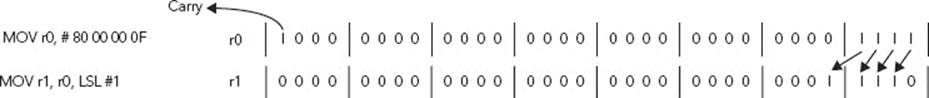
By performing a left shift, the value held in r0 was read in, and then its value was changed by the barrel shifter to 0x1E. Bit 31 was shifted left, effectively leaving the scope of a 32-bit number and was discarded. Bits 4, 3, 2, and 1 were shifted to bits 5, 4, 3, and 2, and a new bit 1 was inserted, or “padded” as a 0, as specified by the LSL instruction. You didn’t ask for a status update, so you didn’t get one. The condition flags in the CPSR remain unchanged. Now look at what would have happened if you had specified the S flag:
MOV r0, 0x8000000F
MOVS r1, r0, LSL #1
Just like before, you insert the value 0x8000000F into r0 and then use the barrel shifter. Just like before, bit 31 leaves the 32-bit scope. Because you are currently working in unsigned 32-bit numbers, the result is considered to be a Carry; the C flag of the CPSR is updated.
By performing manual updates to the CPSR condition flags, you can now execute conditional instructions. You can also execute several conditional instructions if you take care not to modify the CPSR again. After this calculation, you could, for example, have branch instructions depending on several factors. Was your value zero? This is equivalent to a BEQ. No, your result was not equal to zero, so this would not result in a branch. Maybe afterward you would do some quick calculations, and so long as you don’t specify the S flag (or you don’t execute a compare operation), the CPSR condition flags remain unchanged. However, on the next line, you could have a Branch if Carry Set, or BCS, and this time you would branch. Because the CPSR hasn’t been modified since your last MOVS, you can still use the results many lines of code later. This is one of the strong points of ARM; a single calculation can be tested several times.
Now look at a more complete example:
MVN r0, #0
MOV r1, #1
ADDS r2, r0, r1
The first instruction, MVN, is a special instruction that moves a negated number to the specified register. By writing the inverse of 0, you are actually writing 0xFFFFFFFF to the register. The reasons for this will be explained later. For now, don’t worry about the instruction; just remember that r0contains 0xFFFFFFFF.
The second instruction moves the value 1 into r1.
The final instruction is an ADD instruction; it simply ADDs the content of r0 and r1, and puts the result into r2. By specifying S, you can specify that you want to update the CPSR condition flags. Now add 0xFFFFFFFF and 0x1, resulting in 0x100000000. A 32-bit register cannot contain this number; you have gone further than is possible. The logical addition result is held in r2; the result is 0x0.
The result is 0, which is considered to be positive, and so the N (negative) bit is set to 0. Because the result is exactly 0, the Z (zero) bit is set. Now you need to set the correct values for the C and V bits, and this is where things get tricky.
If you are talking about unsigned 32-bit numbers, then the result exceeded 32 bits, so you lost some data. Therefore the C (carry) bit is set.
If you are talking about signed 32-bit numbers, then you essentially did a −1 + 1 operation, and the result is zero. So even though the answer exceeded the 32-bit boundary, the answer did not overflow (meaning the answer did not exceed a signed 32-bit value), and therefore the V (oVerflow) flag is not set.
It is essential to know exactly what sort of result you are expecting. Carry and Overflow do not show the same thing, and the condition codes you specify need to be precise.
Addressing Modes
In ARM assembly, you invariably need to fetch data from one place and put data in another. Your system could just take a set of predefined numbers and do some calculation on them, but that would have severely limited use. Instead, a typical system is constantly fetching data from memory, or from external components (a pressure sensor, a keyboard, or a touch screen, for example).
In assembly, you have several ways of specifying where you want your data to come from. Don’t worry too much about the actual instructions yet, more detail will be given in Chapter 7, “Assembly Instructions,” but for now, concentrate on two instructions. MOV moves data from one register to another, and LDR loads data from a specific place in memory to a register.
One of the most common things that you can do is to put a value into a register. You can do this with an immediate value. An immediate value is an integer but only one of a certain type. For this example, use a simple value, one that is an immediate value. To specify an immediate value, put a hash sign in front of the number, like this:
MOV r1, #42
In this case, tell the processor to put the value 42 into r1.
In some cases, you want to move data from one register to another. This is a simple case and can be specified like this:
MOV r1, r0
This command “moves” the contents of r0 into r1. Converted to C, this is the equivalent of r1 = (int)r0. Technically it is a copy and not a move because the source is preserved, but you look at that more closely later in the chapter. By specifying two registers, you simply copy the value from one to another. However, in some cases, you want to do something called a shift. Shift operations are done by the barrel shifter; more information is available in Chapter 7, “Assembly Instructions.” A shift takes a binary number and “shifts” the bits to the left or to the right.
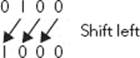
Shifting is a quick way to multiply or divide by powers of 2 or sometimes to read in only a portion of a number. It takes the binary value and “pushes” the numbers in one direction or another, increasing or decreasing by a power of two. This is illustrated in Figure 4-4, where 0100 in binary (4 in decimal) is shifted left, becoming 1000 in binary, or 8 in decimal.
FIGURE 4-4: Binary shift left
To MOV a register after performing a shift, use the LSL or LSR operand.
MOV r1, r0, lsl #2
Like the previous instruction, this command takes the value in r0, and puts it into r1; however before doing that, it performs a left shift of the number by 2 bits. In C, this translate to r1 = (int)(r1 << 2). It is also possible to shift a number to the right:
MOV r1, r0, lsr #4
This is the power of ARM assembly, and one of the reasons why ARM systems are so powerful. Now have a close look at what you have done. You have read in a value from a register, performed a shift, and then put the result into another register. This was all done in one instruction.
LSL and LSR are not the only instructions that you can use; for a complete list, please see the “Barrel Shifter” section in Chapter 7, “Assembly Instructions.”
What happens if you don’t know exactly how much you need to shift? ARM assembly again comes to the rescue; you can specify the contents of a register to perform your shift:
MOV r1, r0, lsr r2
By specifying a register for your shift, r0 can be shifted by the value contained in r2.
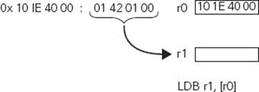
So now you know how to specify registers and how to put arbitrary values into registers, but it doesn’t stop there. However, MOV can put values only from registers or from immediate values into registers, so for the rest of this section, you will have to use another instruction, LDR. LDR reads data from the system memory and puts the result into a register:
LDR r1, [r0]
By putting r0 in square brackets, you tell the compiler that you want to get the value of the memory address stored in r0. For example, r0 might contain 0x101E4000, which is the GPIO1 interface on an ARM Versatile board. Executing this instruction can make the processor look at the memory pointed by r0 and put the result into r1. This is illustrated in Figure 4-5.
FIGURE 4-5: Loading a register from pointer
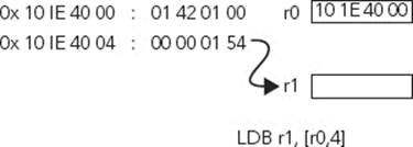
To get the memory contents stored at the address in r0 with an offset, add a number, for example:
LDR r1, [r0, #4]
This works in the same way as your previous example, except now the processor fetches the memory location r0 + 4, or in C, r1 = *(r0 + 1) because you read in 32 bits. This is illustrated in Figure 4-6.
FIGURE 4-6: Loading a register from pointer with offset
Of course, just like before, you can also specify an offset not only as an immediate value, but also as the contents of a register:
LDR r1, [r0, r2]
This instruction fetches the memory location r0, plus the offset r2. Shifts can also be used directly in the instruction, like this:
LDR r1, [r0, r2, lsl #2]
This loads r1 with the memory located at r0, plus the value in r2, divided by 2. The equivalent in C is r1 = *(r0 + ((r2 << 2) /4)). This gives you the possibility to read, for example, a string of characters from memory, using r0 as the base address and r2 as an offset. Of course, after that, you would have to increase the offset register, but there are ways of doing that automatically:
LDR r1, [r0], #4
Just like in a previous example, this instruction takes the data held in the memory location pointed by r0 and places it in r1. However, the immediate value 4 is then added to r0. Consider this example:
MOV r0, #200 ; Put 200 into r0
LDR r1, [r0], #4 ; Reads in memory location 200, then r0 = 204
LDR r1, [r0], #4 ; Reads in memory location 204, then r0 = 208
This is known as post-index addressing because you have your index, and after having used it, you increment the value. Pre-index addressing works on the same principle and is designated by an exclamation mark:
LDR r1, [r0, #4]!
This increases r0 by 4 before fetching the memory. Let’s look at another example:
MOV r0, #200 ; Put 200 into r0
LDR r1, [r0, #4]! ; r0 = 204, then reads in memory location
LDR r1, [r0, #4]! ; r0 = 208, then reads in memory location
ARM ASSEMBLY PRIMER
Like any programming language, Assembly can be a little confusing when starting, and like just about any programming language, there are different dialects, or different ways of writing the same thing. The current standard is known as Unified Assembler Language (UAL) and is a common syntax for both ARM and Thumb (which is discussed in Chapter 7, “Assembly Instructions”).
Loading and Storing
Essential to any calculation, data must first be loaded into one or several registers before you use it. ARM cores use a load/store architecture, meaning that the processor cannot change data directly in system memory; all values for an operand need to be loaded from memory and be present in registers to be used by instructions.
There are only two basic instructions used to load and store data: LDR loads a register, and STR saves a register.
Setting Values
Frequently, you need to update a register with a particular value, not something located in memory. This is useful when comparing data. Is the value of the register r0 equal to 42? You can also use it when writing specific data into a device register; for example, place the data 0x27F39320 into the DDR-II control register to activate system memory.
Branching
Branching is the power of any processor; the capacity of running segments of code depend on a result. It is a break in the sequential flow of instructions that the processor executes.
There are two types of branches possible: relative and absolute. A relative branch calculates the destination based on the value of the PC. Relative branches can be in the range of +/– 32 M (24 bits x 4 bytes) for ARM, and +/– 4 M for Thumb. Because branch instructions are PC-relative, the code generated is known as relocatable; it can be inserted and run at any address.
Absolute branching works differently. Absolute branches always jump to the specified address and are not limited to the +/– 32 M barrier. They use a full 32-bit register, so this value needs to be entered before, costing cycles, but the advantage is that you can access the full 32-bit address range.
Conditional branching is the basis of every system. A computer is not a computer if it cannot be told to do one thing or another, depending on a previous result. Understanding branching is vitally important.
Branching can be done by linking, thereby saving the next instruction address, allowing the program to return to the exact same location after executing a subroutine. Branching can also be done without saving the link register, which is often used during loop instructions.
All processors can branch, but ARM systems take this a step further. ARM cores can execute either ARM assembly instructions, or Thumb instructions, and switching between the two is as easy as issuing a branch and exchange instruction.
All the jump instructions are detailed later in Chapter 7, “Assembly Instructions.”
Mathematics
Because every value inside a processor is a number, everything that is done to that number is in some way mathematical. A graphical user interface consists of lines and rectangles, and resizing windows often involves manipulating numbers. Listening to digital music often involves heavy and repetitive mathematics. ARM cores contain a complete instruction set that can handle just about any calculation required for low-end microcontrollers all the way to advanced application processors.
Assembly instructions attempt to be readable; MUL is short for multiplication, SUB subtracts, and SBC subtracts with carry, and in all cases, the variables are in human-readable format.
Understanding an Example Program
Now look at an example program, without having had a look at all the instructions available. This is a mystery routine, and all that is known is that it accepts a single parameter: r0.
sum
MOV r1,#0
sum_loop
ADD r1,r1,r0
SUBS r0,r0,#1
BNE sum_loop
sum_rtn
MOV r0,r1
MOV pc,lr
At a glance, this is an easy routine, but it doesn’t make much sense. Now break that down into several sections:
sum
MOV r1,#0
This portion of code “moves” the value 0 into r1. Presumably, you use r1 during a calculation, and this is just to set the parameter. In C code, it would be the equivalent of int x = 0.
sum_loop
ADD r1,r1,r0 ; set sum = sum+n
SUBS r0,r0,#1 ; set n = n-1
BNE sum_loop
The first instruction adds together the values held in r1 and r0 and puts the result in r0. The second line is a subtract instruction, SUB, but because the S is present at the end of the instruction, it also updates the condition flags of the CPSR. The instruction takes the value 1 from the value held in r0and puts the result back into r0. So, r0 = r0 – 1, or, in C, r0--. The third instruction is a branch operation, making the execution “jump” to a specific location, but only if the NE condition is met. So, this instruction jumps back to the beginning of the code if r0 is not equal to zero.
So, r0 holds a value, and r1 equals r1 plus the value held in r0. Then, subtract 1 from r0, and repeat the process while r0 isn’t equal to 1. If you started off with the value 5, the operation would have been 5 + 4 + 3 + 2 + 1, before continuing. In other words, this routine takes a number n and returns the result of 1 + 2 + 3 + ... + n:
sum_rtn
MOV r0,r1
MOV pc,lr
So, what happens here? In the first instruction, the register r1 is “moved” into r0. In the second instruction, the Link Register is “moved” into the Program Counter, but why? ARM functions return their result in r0 so that is why the temporary register, r1, must be first copied into r0; otherwise the result would be lost. As for the Link Register, it is a way for returning from a Branch with Link, or a specific way of calling a subroutine. This program was a subroutine, and now it returns back to the main program after completing its task.
Congratulations; you have just survived your first ARM assembly program!
SUMMARY
In this chapter, I have given a brief introduction to ARM Assembly, its uses and applications, and a brief introduction to some of the instructions and options that make ARM assembly unique. You have considered the different condition codes that make most ARM instructions conditional, and I explained what makes this so powerful. I have also shown an example program in assembly, and you’ve seen that it isn’t too difficult to understand assembly.
In the next chapter, I will give a few example applications, from the simplest emulated program to two real-world programs using evaluation boards.
All materials on the site are licensed Creative Commons Attribution-Sharealike 3.0 Unported CC BY-SA 3.0 & GNU Free Documentation License (GFDL)
If you are the copyright holder of any material contained on our site and intend to remove it, please contact our site administrator for approval.
© 2016-2026 All site design rights belong to S.Y.A.