Professional Embedded ARM Development (2014)
Part I. ARM Systems and Development
Chapter 7. Assembly Instructions
WHAT’S IN THIS CHAPTER?
Different assembly instructions
Assembly arithmetic
Different branch instructions
Use of assembly instructions
Assembly is just like any other computer language; you must first know the basics: the syntax of the language. After you know how to speak assembly, then comes the interesting part — vocabulary.
ARM cores follow a Reduced Instruction Set Computing (RISC) design philosophy. They have fewer instructions than CISC counterparts, but each individual instruction, being simpler, is also faster. Just like a box of Legos, it is possible to make amazing sculptures with simple pieces. Learning ARM Assembly is the same; after you grasp the power of each simple instruction, it becomes easy to read and write programs.
Because most ARM cores now support two instruction sets, ARM and Thumb, ARM created the Unified Assembler Language (UAL) to write programs for both languages. The following chapter is written in UAL, and as such, the instruction format should be supported by all the modern compilers and environments.
ARM assembly instructions have gone through different versions, as architectures have added more and more instructions. Some cores may have more instructions due to its architecture; for more information, consult the manufacturer’s documentation. This documentation will contain the ARM Architecture version. ARM’s documentation will list all the instructions available.
MOVEMENT
Movement instructions are used to transfer data into registers, either the data from another register (copying from one register to another), or by loading static data in the form of an immediate value.
The following sections discuss the instructions used for movement.
MOV
MOV{<cond>}{S} Rd, Rs
MOV (Move) copies data into a register. The source can either be a register or static information. The destination is always a register. When using static data, MOV can only use immediate value.
Contrary to most Thumb instructions, MOV can access low registers and high registers. The ARM implementation can access any register.
To move static data into a register, specify the source after the destination:
MOV r0, #42
which moves the constant 42 into register r0.
Then use:
MOV r1, r2
which moves the contents of r2 into r1, leaving r2 untouched.
Use this:
MOV r0, r0
to move the contents of r0 into r0, equivalent to a NOP (no operation). While alone it has no use, it can be used for padding, to keep data aligned.
MVN
MVN{<cond>}{S} Rd, Rs
MVN (Move Negated) copies a negated value into a register (destination = NOT(source)). This is useful for storing some numbers that MOV cannot handle, numbers that cannot be expressed as an immediate value, and for bitmaps that are mainly composed of 1s.
For example, due to the nature of immediate values, MOV cannot store 0xFF00FFFF, but this result can be achieved by issuing a MVN command with 0x00FF0000. Because MVN will negate the number, and because 0x00FF0000 can be expressed as an immediate value, it can be achieved in a single instruction.
MOV r0, #42
MVN r1, r0
This copies an inverse of r0 into r1. r1 now contains −43. 42 in binary is 0000 0000 0010 1010, and the inverse is 1111 1111 1101 0101, or −43 in decimal.
MOVW
MOVW (Move Wide) copies a 16-bit constant into a register while zeroing the top 16 bits of the target register. This is available in ARMv7 cores and higher. MOVW can use any value that can be expressed as a 16-bit number.
MOVW is unavailable in the original Thumb technology and was introduced in the Thumb-2 extension.
When using:
MOVW r0, #0x1234
r0 now contains the value 0x00001234, no matter what was there before.
MOVT
MOVT (Move Top) copies a 16-bit constant into the top part of a register, leaving the bottom half untouched. This is available on ARMv7 cores and later.
MOVT is unavailable in the original Thumb technology and was introduced in the Thumb-2 extension. In the following example, the first instruction clears the top half of r0, setting the bottom half to 0x0000face. The second instruction sets the top half of the register, leaving the second half untouched. The result will be 0xfeedface.
MOVW r0, #0xface
MOVT r0, #0xfeed
NEG
When using:
NEG{<cond>}{S} Rd, Rs
NEG (Negate) takes the value in Rs and performs a multiplication by −1 before placing the result into Rd.
Example: Loading a 32-Bit Constant from the Instruction Stream
This is one of the pitfalls of embedded programming. Say you want r0 to contain 0xdeadbeef. An immediate thought is to use MOV:
MOV r0, 0xdeadbeef
Technically, this isn’t possible. Some assemblers might accept this, but it isn’t exactly what you are doing, and the assembler will make modifications. If the assembler fails, there will be cryptic messages about what went wrong. But what did go wrong?
Remember, all ARM instructions are 32-bit wide. In these 32 bits, there is the instruction itself, and in the case of MOV, the destination register information and the destination value. Therefore, quite logically, it is not possible to encode an arbitrary 32-bit value in a 32-bit instruction — or at least not always.
When using an immediate value for an operation, the processor uses an 8-bit number and a rotation factor. Using this scheme, you can express immediate constants such as 0x000000FF, 0x00000FF0, 0xFF000000, or 0xF000000F. In this case, an 8-bit number, 0xFF, is used and rotated as needed.0x000001FF is not possible because 0x1FF is not an 8-bit number. 0xF000F000 is not possible either because there is no rotation possible allowing such a number. So you can load a 32-bit integer into a register, as long as it can be expressed as an immediate value in this format. The reason for this is simple. In C, constants tend to be small. When they are not small, they tend to be bitmasks. This system provides a reasonable compromise between constant coverage and encoding space.
When the integer is a complete 32-bit number that cannot be expressed as an immediate value, there are three choices. Either the value is fetched from memory, or it is loaded in two different instructions or in four instructions.
When fetching the values from memory, you need to make sure that the value is in the instruction memory, close to the instruction, as follows:
loaddata
ldr r0, [pc, #0] @ Remember PC is 8 bytes ahead
bx lr
.word 0xdeadbeef
Because you know where your data is, you can simply tell the CPU to fetch it and to load it using an LDR instruction. Remember that with an ARM pipeline, the PC is always two instructions ahead of your current instruction. The compiler automatically does this for you.
Another solution available on ARMv7 cores and higher is to load the data in two steps. MOVW and MOVT can help to do this, by loading two 16-bit values into a register. These instructions are specially designed to accept a 16-bit argument. MOVW can move a 16-bit constant into a register, implicitly zeroing the top 16 bits of the target register. MOVT can move a 16-bit constant into the top half of a given register without altering the bottom 16 bits. Now moving an arbitrary 32-bit constant is as simple as this:
MOVW r0, #0xbeef @ r0 = 0x0000beef
MOVT r0, #0xdead @ r0 = 0xdeadbeef
Both of these examples take up the same amount of code. The second approach has the advantage of not requiring a memory read because the values are encoded directly into the instructions.
It can be confusing to have two 16-bit variables. It is much easier to have a single 32-bit variable, exactly what will be loaded into a register. MOVW and MOVT work only with 16-bit values. To simplify this, the GNU assembler enables some flexibility, with the :upper16: and :lower16: prefixes, as shown in this example:
.equ label, 0xdeadbeef
MOVW r0, #:lower16:label
MOVT r0, #:upper16:label
Now everything becomes more readable and safer.
In the case in which you cannot use ARMv7 code, and you don’t want to read the data from RAM, there is a third option, which takes up four instructions. First, you can load part of the register using an immediate value and then repeat an ORR instruction.
MOV r0, #0xde000000 @ r0 = 0xde000000
ORR r0, r0, #0x00ad0000 @ r0 = 0xdead0000
ORR r0, r0, #0x0000be00 @ r0 = 0xdeadbe00
ORR r0, r0, #0x000000ef @ r0 = 0xdeadbeef
This is not the most memory-efficient but is most often faster than reading the value from RAM.
In some rare cases, you can load a large 32-bit integer into a register in one instruction on the condition that its inverse can be expressed as an immediate. For example, you want to put the value 0xFFFFFAFF into a register, which looks suspiciously like a bit mask. You cannot express this number as an immediate value, so you cannot load it with a simple MOV. You can still use MOV and ORR, or MOVW and MOVT, but in this case, there is another option. The inverse of 0xFFFFFAFF, or NOT(0xFFFFFAFF) is 0x00000500, which can be expressed as an immediate value. Now, you can use Move Not, orMVN, to load your register.
MVN r0, #0x500
ARITHMETIC
Arithmetic instructions are the basis of any central processing unit (CPU). Arithmetic instructions can do most of the basic mathematical instructions, but there are a few exceptions. ARM cores can add, subtract, and multiply. Some ARM cores do not have hardware division, but there are, of course ways to do that.
All the arithmetic instructions work directly to and from registers only; they cannot read from the main memory or even the cache memory. To make calculations, the data must previously be read into registers.
Arithmetic instructions can work directly on both signed and unsigned numbers because of the two’s complement notations.
The following is a discussion of some of the mathematical instructions included on many ARM cores.
ADD
ADD adds together two registers and places the result into a register, such as:
ADD{cond}{S} Rd, Rm, Rs
MOV r1, #24
MOV r2, #18
ADD r0, r1, r2
This adds Rm and Rs and puts the result into Rd. In this example, r0 now contains 42.
ADDS r0, r1, r2
This adds r1 and r2 and puts the result into r0. If the result exceeds the register width, it updates the Carry flag in the CPSR. This can be useful on 32-bit CPUs to add 64-bit numbers together using ADC.
ADC
ADC (Add with carry) adds two numbers together and also uses the carry flag. For example, if you want to add two 64-bit numbers on a 32-bit CPU, you would do the following. r2 and r3 contain the first number; r4 and r5 contain the second number. You can put the result in r0 and r1.
ADDS r0, r2, r4 ; Adds the low words, update status
ADCS r1, r3, r5 ; Add the high words, using carry, update status
This example first adds the low words, storing the result in r0, and updates the status. If the end result is larger than 32-bits, the carry flag is set. When you ADC the result, you add both r3 and r5, and also add the carry bit if previously set. If the carry bit is not set, this command is equivalent toADD. However, the first command is always ADD because you don’t want a previous carry bit to interfere. Also, remember to update the status register.
SUB
SUB subtracts one number from another, placing the result in a register.
SUB{cond}{S} Rd, Rm, Rs
For example:
SUB r0, r1, #42
This instruction takes the value in r1, and subtracts the value in the second operand (in this example, 42) and places the result in r0.
SBC
SBC (Subtract with carry) is like the SUB instruction. SBC subtracts two numbers, but if the carry flag is set, it further reduces the result by one. Using a mixture between SUB and SBC, you can perform 64-bit calculations:
SUBS r0, r0, r2 ; Subtract the lower words, setting carry bit if needed
SBC r1, r1, r3 ; Subtract upper words, using borrow
RSB
RSB (Reverse subtract) is like SUB; RSB subtracts the value of two registers but reverses the order of the operation. This can be useful with the barrel shifter, effectively allowing the barrel shifter to be used on the first operand during subtraction. For example:
MOV r2, #42
MOV r3, #84
SUB r0, r2, r3 ; r0 = r2 - r3
RSB r1, r2, r3 ; r1 = r3 - r2
In this example, the SUB instruction takes the value in r2, subtracts the value in r3, and puts the result into r0. Using the same variables, RSB takes the value in r3, and subtracts the value in r2 before placing the result into r1. It can save instructions when the barrel shifter is required, for example:
MOV r2, #42
MOV r3, #84
MOV r4, r2, LSL #1 ; Multiply r2 by two
SUB r0, r4, r3 ; r0 = (r2 * 2) - r3
In this example, r2 needs to be multiplied by two before continuing. Then the subtract instruction takes r4 (which is r2 multiplied by two), and subtracts the value of r3, before placing the result in r0. This can be written in another way using RSB:
MOV r2, #42
MOV r3, #84
RSB r1, r2, r3, LSL #1 ; r1 = (r3 * 2) - r2
It can also be used for quick multiplications by some values that are not powers of two:
RSB r0, r1, r1, LSL #4 ; r0 = (r1 << 4) – r1 = r1 * 15
RSC
RSC (Reverse subtract with carry) is like RSB. It inverses the order of operation, but because it uses carry, it can further reduce the result by one if the Carry bit is set.
Example: Basic Math
When using basic math, you frequently see fairly large calculations on a single line of code. This is an example of a common function in C:
r0 = (r1 + r2) – r3;
The same can be written in assembly as follows:
ADD r0, r1, r2 ; compute a + b
SUB r0, r0, r3 ; Complete Computation of x
It is also useful to understand how Arithmetic functions work, since they are one of the keys to optimization. As stated previously, it is often quicker to rotate a number when multiplying or dividing by a power of two. When multiplying or dividing by a number that is a power of two plus or minus one, arithmetic can provide an optimized solution, as shown in the following example:
ADD r0, r1, r1, LSL #3 ; r0 = r1 + (r1 * 8) = r1 * 9
RSB r0, r1, r1, LSL #4 ; r0 = (r1 * 16) – r1 = r1 * 15
SATURATING ARITHMETIC
Normal mathematical operations are prone to overflow. If the result of a mathematical operation is bigger than the container, then overflow will occur, sometimes with surprising results. For example, the largest number possible in an unsigned byte is 255. When adding 128 and 128 together, the result is 256, or in binary 1 0000 0000. Put into a byte, this result is zero. An overflow has occurred, and precision has been lost. More surprising, the result gives no indication that the number was large.
Saturating arithmetic is a version of arithmetic in which all operations are limited to a fixed range. In this case, the limit of an operation is the size of the container; an unsigned byte will never go above 255. In the previous example, 128 plus 128 would give something mathematically wrong; it would attempt to go above 255 and would not go any further. To signal that an overflow has occurred, the Q flag is set in the CPSR.
ARM Saturating instructions work on signed 32-bit boundaries (meaning that the largest number possible is 231 – 1, and the smallest number possible is −231), unsigned 32-bit boundaries (ranging from 0 to 232), and 16-bit signed and unsigned boundaries.
Contrary to the other ARM status flags, the Q bit is a sticky flag. Saturating arithmetic instructions can set the flag, but cannot clear it. In the event of several saturating instructions, if one of the instructions overflows, the Q bit is set. Subsequent instruction will not clear the flag, even if the result does not saturate. In this situation, it is not always possible to know which instruction saturated, but it is possible to know if saturating occurred somewhere during the algorithm.
The following is a discussion of some of the saturating instructions and their uses.
QADD
QADD{cond} Rd, Rm, Rn
QADD executes a saturating add on two numbers, Rm and Rn, placing the saturated result in Rd. The result will not overflow a signed 32-bit value. It is used in the same way as the ADD instruction, but does not update condition codes.
QSUB
QSUB{cond} Rd, Rm, Rn
QSUB executes a saturating subtraction, subtracting the value in Rn from the value in Rm. The result is placed in Rd.
QDADD
QDADD{cond} Rd, Rm, Rn
QDADD (Saturating Double Add) is an instruction that does two things. It calculates the result of a saturating multiply of Rn by two, before performing a saturating addition of the result with Rm. In short, this operation calculates SAT(Rm + SAT(Rn * 2)).
Saturation can occur on the doubling, on the addition, or possibly both. In all cases, the Q flag is set. If saturation occurs on the doubling but not on the addition, the Q flag is set, but the final result is unsaturated.
MOV r1, #1 ; r2 contains 1
MOV r2, #0xFF ; r1 contains 255
QDADD r0, r1, r2 ; r0 contains 1 + (255 * 2)
In this example, there is no overflow, and no saturation. The Q bit is not set. In the next example, you see what happens during an overflow.
MOV r1, #-1 ; r1 contains -1
MVN r2, #0x7f000000 ; r2 contains a very large number
QDADD r0, r1, r2 ; r0 contains 231 – 1
In this example, the value in r2 was multiplied by 2, but that value was bigger than a signed 32-bit value (0x7F 00 00 00 x 2 = FE 00 00 00, higher than the maximum 7F FF FF FF), so the result was saturated to 231 – 1. Because the multiplication saturated, the Q bit was set. Now the saturated result is added to the value in r1; in this case, minus one. The end result is 231 – 2, which is not a saturated number, but because the Q bit was set, you can tell that the multiplication saturated, and the addition did not.
QDSUB
QDADD{cond} Rd, Rm, Rn
QDSUB (Saturating Double Subtraction) calculates Rm minus two times Rn. In short, it calculates SAT(Rm – SAT(Rn * 2)). Just like QDADD, saturation can occur on the doubling, or the subtraction, or both.
MOV r1, #1 ; r2 contains 1
MOV r2, #0xFF ; r1 contains 255
QDSUB r0, r1, r2 ; r0 contains 1 - (255 * 2)
DATA TRANSFER
ARM processors use a load-and-store architecture; they cannot do raw calculations directly from system memory. You must first load data from the system memory into one or several registers before performing any calculation.
In architectures before ARMv6, data loaded from or saved to system memory had to be aligned; 32-bit words must be 4-byte aligned, and 16-bit half-words must be 2-byte aligned. Bytes have no restriction. In ARMv6, this restriction was relaxed.
The following is a discussion of some of the data transfer instructions and their uses.
LDR
LDR{<cond>}{B|H} Rd, addressing
LDR (Load) is an instruction used for moving a single data element from system memory into a register. It supports signed and unsigned words (32 bit), half-words (16 bit), and bytes.
LDRB, short for LDR Byte, is used to load a byte into a register from system memory. LDRH works the same way with a half-word. Signed versions are also available where LDRSB loads a signed byte and LDRSH loads a signed half-word.
To load r0 with the contents of the memory pointed to by the register r1, use the following:
LDR r0, [r1]
After calculations have been done, the data can be written back out into system memory using STR:
STR r0, [r1]
Reading in bytes and half-words is just as easy. For example, in the event of a C structure containing bytes and half-words, it is possible to use a pre-index offset to load parts of the structure, using the base address of the structure itself:
LDRH r2, [r1, #4]
LDRB r3, [r1, #6]
NOTE Pre-index addressing is explained in Chapter 4, “ARM Assembly Language.”
STR
STR{<cond>}{B|H} Rd, addressing
STR is the store command. It takes a register and places the 32-bit value into system memory. It supports the same indexing as LDR. Just like LDR, STR also has byte and half-word variants — STRB for bytes, and STRH for half-words.
LDR r0, [r1, #20] ; load memory from the address in r1, plus 20 bytes
ADD r0, r0, #1 ; add one to r0
STR r0, [r2, #20] ; save r0 to system memory, in r2 + 20 bytes
Example: memcpy
The memcpy routine is one of the most widely studied and optimized routines. The idea is extremely simple; move a portion of memory from one location to another. This happens often in embedded systems, so fine-tuning memcpy is often essential.
You can copy 1 byte at a time, and although the result might not be optimal, it does get the job done. For example, this routine is called wordcopy. The source address goes into r0, and the destination address goes into r1. The amount of words to copy is placed in r2.
wordcopy
LDR r3, [r0], #4 ; load a word from the source and
STR r3, [r1], #4 ; store it to the destination
SUBS r2, r2, #1 ; decrement the counter
BNE wordcopy ; ... copy more
On the first line, the memory location of the word to read is held in r0. The routine loads the memory location at the location held by r0, and then increments r0 by 4, known as post-indexing. The value read is located in r3.
After the value has been read and stored into a register, it is time to write it back out into memory. This is done in the second instruction, STR. Just like the previous line, it writes out the contents of r3 into main memory to the memory address located in r1. When the procedure is complete, SUBSsubtracts one from r2 and places the result back into r2, updating the CPSR. Finally, BNE breaks the program and returns to the start only if the Zero flag is set. When r2 reaches zero, the program continues.
An optimized routine would read in several words at a time. You see this later in the “Multiple Register Data Transfer” section.
LOGICAL
Logical operators perform bit-wise operations on two numbers. There are four logical operations: AND, NOT, OR, and EOR. In theory, logical operators can be done on multiple inputs, but with assembly these instructions accept exactly two inputs and produce one output. They can be thought of as:
AND outputs true only if both inputs are true.
OR outputs true if at least one input is true.
EOR outputs true if exactly one input is true.
NOT inverses the input; it will return true if the input is false.
AND is used extensively for “masking”; AND-ing a number with one produces the original output, whereas AND-ing with zero produces zero. Similarly, OR-ing a bit with one produces one as the output, whereas OR-ing a bit with zero produces the original output.
The following is a list of logical instructions used on ARM processors.
AND
AND performs a logical AND between the two operands, placing the result in the destination register.
AND r0, r0, #3 ; Keeps bits 0 and 1 of r0, discard the rest
EOR
EOR (Exclusive-OR) is a useful instruction when programming bitwise operations. EOR effectively “switches” bits.
MOV r0, #0xF ; Put binary 1111 into r0
EOR r0, #2 ; 1111 EOR 0010 = 1101
EOR r0, #2 ; 1101 EOR 0010 = 1111
ORR
ORR produces the logical OR between two registers and writes back the result.
MOV r1, #42 ; r1 contains b0010 1010
MOV r2, #54 ; r2 contains b0011 0110
ORR r0, r1, r2 ; r0 now contains b0011 1110
BIC
BIC is the equivalent of AND NOT; in C, it is equivalent to operand1 & (!operand2).
BIC r0, r0, #3 ; clear bits zero and one of r0
CLZ
CLZ{cond} Rd, Rm
CLZ (Count Leading Zeros) is an instruction that takes the register Rm, counts the number of leading zeros, and places the result in Rm. For example, if Rd equals zero, then CLZ returns 32 (because there are 32 zeros). If bit 31 is set, then CLZ returns zero.
COMPARE
Compare instructions are instructions that do not return any results, but set condition codes. They are extremely useful, as they allow the programmer to make comparisons without using a new register, but the CPSR Condition flags are updated. The CPSR is updated automatically; there is no need to specify the S option. There are four instructions, all performing a logical ADD, SUB, OR, and AND.
The following is a list of comparison instructions used on ARM processors.
CMP
The CMP instruction is used to compare two numbers. It does this by subtracting one from the other, and updating the status flags according to the result.
MOV r0, #42
MOV r1, #42
CMP r0, r1 ; Compares r0 and r1,
CMN
CMN compares two values, updating the CPSR. It is the equivalent to operand1 + operand2.
TST
TST is a test instruction that tests either if one or more bits of a register are clear, or at least one bit is set. There is no output for this instruction; instead, the CPSR condition flags are updated. This is the equivalent of operand1 and operand2.
LDR r0, [r1] ; Load the memory pointed by r1 into r0
TEQ r0, 0x80; Is bit 7 of r0 set?
BEQ another_routine ; If so, branch
Another way of writing this sequence is:
TST r0, #(1<<7) ; is bit 7 set?
BEQ another_routine
TEQ
TEQ compares operand1 and operand2 using a bitwise exclusive OR, and tests for equality, updating the CPSR. It is the equivalent to an EORS instruction, except that the result is discarded. This is especially useful when comparing a register and a value, returning zero when the registers are identical, and returning 1 for each bit that is different.
LDR r0, [r1] ; Load the memory pointed by r1 into r0
TEQ r0, 0x23 ; Is r0 equal to b0010 0011?
BEQ another_routine ; If so, branch
BRANCH
Branch instructions are the core of any microprocessor, providing the possibility to execute portions of code depending on a result. Branch operations are used not only to branch to other routines, but also to do iterations on the current code.
Most assemblers hide the details of a branch instruction by using labels, a convenient way of marking memory locations. Labels are placed at the beginning of a line and are used to mark an address that can be used later by the assembler to calculate the branch offset.
The following is a list of branch instructions used on ARM processors.
B
B (Branch) tells the current program counter that the next instruction will be at the address specified by setting PC to <address>. This is a permanent branch; no return is possible. It is used mainly in loops or to give control to another part of the program.
[ ... ]
B fwd
MOV r0, r0 ; This command is never run
fwd
[ ... ]
In this example, the MOV command is never run because of the unconditional break before it.
Branching is also used to branch backward, creating a simple loop structure, for example:
back
[ ... ]
B back
Of course, this is especially useful when using condition codes. For example, to loop some instructions waiting for a result to be equal to 42, this code could be used:
back
[..]
CMP r0, 42
BNE back
BL
BL (Branch with Link) branches in the same way as the B instruction. The PC will be changed with the address specified, but the address just after BL will be put into r14. This allows the program to return where it was when the subroutine has finished.
[ ... ]
[ ... ]
BL calc
[ ... ] ; next instruction
[ ... ]
calc
ADD r0, r1, r2
BX lr ; Return to where we were
In this example, during the main application, you branch with link to calc. After the calculation is done, you can return to the main program via a BX instruction.
BX
BX (Branch and Exchange) is an instruction that enables the program to switch between ARM state and Thumb state, for cores supporting both ARM and Thumb states. This enables seamless integration of ARM and Thumb code because the change is done in a single instruction.
The link logic is held in the destination address. Because ARM cores require instructions to be naturally aligned, the lower address bits are not used for instruction fetches. By using this, the BX instruction can know if the destination code is Thumb or ARM. If bit 0 of the destination address is set, then the T flag of the CPSR is set, and the destination code is interpreted as Thumb. If bit 0 of the destination address is clear, then the T flag of the CPSR is cleared, and the destination code is interpreted as ARM.
BLX
BLX (Branch with Link and Exchange) is like the BX instruction. This instruction also changes to and from the Thumb state, but also updates the Link register, allowing to return to the current location.
Example: Counting to Zero
By using the condition Branch if Not Equal, you can create a small loop. In C, this is the equivalent of for (i = 16; i != 0; i--).
MOV r0, #16
countdown:
SUB r0, r0, #1
BNE countdown
# Rest of program
Example: Thumb Interworking
Switching between Thumb code and ARM code is known as interworking and is a critical part of any program that uses both ARM and Thumb. In C, this is perfectly transparent because the compiler and linker automatically handle the state transitions. However, when writing assembly code by hand, or when debugging, you must know how to handle interworking.
Compilers and linkers work together in interlinking, since the compiler does not know if the destination of a branch is in ARM mode or Thumb mode. The compiler will use BX to return, and the linker will look closely at the destination and change the BX instruction to BLX if required, or by inserting veneers.
; *****
; arm.s
; *****
PRESERVE8
AREA Arm,CODE,READONLY ; Name this block of code.
IMPORT ThumbProg
ENTRY ; Mark 1st instruction to call.
ARMProg
MOV R0,#1 ; Set R0 to show in ARM code.
BLX ThumbProg ; Call Thumb subroutine.
MOV R2,#3 ; Set R2 to show returned to ARM.
END
; *******
; thumb.s
; *******
AREA Thumb,CODE,READONLY ; Name this block of code.
THUMB ; Subsequent instructions are Thumb.
EXPORT ThumbProg
ThumbProg
MOVS R1, #2 ; Set R1 to show reached Thumb code.
BX lr ; Return to the ARM function.
END ; Mark end of this file.
What Is MOV pc, lr?
In some legacy code, functions return using MOV pc, lr. This effectively returns the data in the link register to the program counter, which sounds like it would work perfectly, but it doesn’t always. ARM deprecated this return method in 1995. The reason is simple: When returning in this fashion, the processor does not change state. If the MOV function was coded for Thumb, and the return code was in ARM, then the processor would not make the switch between the two states, resulting in an exception. While it is possible to return using a MOV pc, lr, it isn’t context safe, and it is much safer to always use the BX instruction, even when not changing states.
MULTIPLY
These commands multiply 32-bit numbers into a 32-bit or 64-bit number. ARM cores use a fast hardware multiplier; most multiplication instructions are executed in three cycles or less.
MUL
Multiply two numbers together, where Rd = Rm * Rs.
MUL{cond}{S} Rd, Rm, Rs
MOV r1, #42
MOV r2, #4
MUL r0, r1, r2 ; r0 now contains 4 x 42, 168
On ARMv5 or earlier architectures, multiplication must never be done using the same register for both values. The results are UNPREDICTABLE, meaning that the result of an instruction cannot be relied upon.
To calculate the square of a number on ARMv5, two registers were necessary:
MOV r1, #42
MOV r2, r1
MUL r0, r1, r2
This restriction was relaxed in ARMv6MOV r1, #42
MUL r0, r1, r1
MLA
Multiply two numbers together with accumulate. MLA is used to multiply registers to create a 32-bit result, which is then added to another value, producing the final result.
MLA{cond}{S} Rd, Rm, Rs, Rn
It is the equivalent to Rd = (Rm * Rs) + Rn.
MOV r1, #4
MOV r2, #10
MOV r3, #2
MLA r0, r1, r2, r3 ; r0 = (r1 x r2) + r3, in this case, 42
You cannot use r15 for any calculations.
UMULL
UMULL (Unsigned Multiply Long) multiplies two unsigned 32-bit numbers to a 64-bit number, stored in two registers, where RdHi, RdLo = Rm * Rs.
UMULL{cond}{S} RdLo, RdHi, Rm, Rs
UMLAL
UMLAL (Unsigned Multiply with Accumulate Long) multiplies two 32-bit numbers to a 64-bit number with accumulation, where RdHi, RdLo = RdHi, RdLo + ( Rm * Rs ).
UMLAL{cond}{S} RdLo, RdHi, Rm, Rs
SMULL
SMULL (Signed Multiply Long) multiplies two signed 32-bit numbers to a 64-bit number, stored in two registers, where RdHi, RdLo = Rm * Rs:
SMULL{cond}{S} RdLo, RdHi, Rm, Rs
SMLAL
SMLAL (Signed Multiply with Accumulate Long) multiplies two signed 32-bit numbers to a 64-bit number with accumulation, where RdHi, RdLo = RdHi, RdLo + ( Rm * Rs ).
DIVIDE
In the early days of ARM, some legacy processors did not have hardware division. A design decision traded silicon area against functionality at a time where the speed of division was not critical. It is for this reason that some cores did not have hardware division, and for the same reason, division was done in software. Dividing by powers of two was simple, since it involves shifting, but otherwise, highly optimized software was developed. Today things have changed, and ARM has introduced hardware division on several processors, but not all of them.
In the absence of a hardware divide instruction, division in machine code is exactly the same as division by any other method; it is simply a matter of repeated subtraction. When you divide 42 by 7, what you really want to know is how many times the number 7 fits into the number 42, or in other words, how many times you can subtract the smaller number from the bigger number until the bigger number reaches zero. The answer in this case is, of course, 6. There are several ways to divide, and C libraries contain a lot of information on that subject, but if you need to optimize heavily, you may need to create your own routines in assembly for particular divisions (for example, when a routine will divide a number only by 7, and no other number). For general purpose optimization, standard libraries have gone through years of optimization.
Later cores do support hardware division, namely the Cortex-M3 and Cortex-M4, the Cortex-R4 and the Cortex-R5, and the Cortex-A15 with its sister processor, the Cortex-A7.
You can divide by some numbers using shifts, and the compiler chooses to optimize in this way where it can, but it cannot always simplify. Sometimes you need to be explicit in your code. By using shifts, you can divide by powers of 2.
MOV r0, r0, LSR #1 ; Divide r0 by 2
SDIV
SDIV{cond} {Rd,} Rn, Rm
SDIV (Signed Divide) performs a signed integer division of the value in Rn by the value in Rm. If Rd is omitted, the destination register is Rn. Operations on SP and LR are prohibited.
SDIV r0, r1, r2 ; r0 = r1/r2
SDIV r3, r4 ; r3 = r3 / r4
UDIV
UDIV{cond} {Rd,} Rn, Rm
UDIV, or Unsigned divide, uses the same syntax as SDIV. UDIV performs integer division on unsigned numbers.
MULTIPLE REGISTER DATA TRANSFER
There are instructions to load and to save a single register to and from memory, but in most applications using several variables, it is often impractical to save a single register each time. Fortunately, ARM has a system to save several registers to memory, and to take into account endianness and memory location.
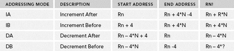
Before presenting the instructions, you must understand that unlike most instructions, these instructions have a <mode> parameter. These instructions can be programmed to increment or to decrement before or after each transfer. Therefore, when transferring several registers, subsequent registers can either go up in memory space or down. The register used to point to the memory location (the base register) can either be increased or decreased before, or after, each read/write. In short hand, they are written IA, IB, DA, or DB. This is illustrated in the following table. The base register Rndetermines the source or destination for the Load/Store Multiple instruction. This register can optionally be updated following the transfer by including an exclamation mark after the register, similar to the single-register load/store command.
The easiest way to understand the differences between the modes is by an image. Figure 7-1 shows the result of four store operations, all using a base register of 0x8000.
FIGURE 7-1: Load/Store Multiple results
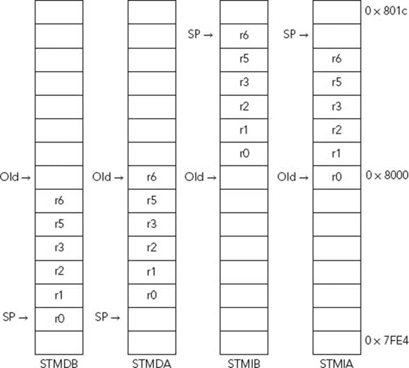
With these options, the program has entire control over the direction of the memory reads/writes and also the resulting stack pointer.
STM
STM{addr_mode}{cond} Rn{!}, reglist{^}
STM is the “store multiple” instruction. STM takes one or several registers and places them in a block of memory pointed by the base register. The initial registers remain untouched. If the optional “!” is specified, the base register is updated according to the mode.
When encoded into the instruction, the registers are expressed as bits, meaning that any combination (or all the available registers) can be used. The registers are then read in logical order (r0 – r15), not the order expressed on the instruction line.
STMFD r9!, {r0-r4, r6, r8} ; Stores the registers in Full Descending mode
LDM
LDM is the “load multiple” instruction. Just like STM, LDM takes a list of registers and loads them from memory. The original memory location remains untouched.
LDMFD r9!, {r0-r4, r6, r8} ; Loads the registers in Full Descending mode
BARREL SHIFTER
The Barrel Shifter is a functional unit that can be used in a number of different circumstances. These commands are not ARM instructions but are added to operand2. They enable complex calculations, still using only one assembly command. They are, however, separate Thumb instructions and cannot be added to the end of an instruction.
Shift operations, basically, move the bits in a register to the left or to the right, filling in vacant bits with 0s or 1s. This is the equivalent to multiplying or dividing by powers of 2. This brings you to the question, “Why aren’t shift and rotate operations real instructions, instead of just using the barrel shifter?” Surely this will just complicate things? In reality, it is quite the opposite. A shift or a rotate can be performed at the same time as any ARM-state data processing instruction, increasing speed considerably and providing denser code.
LSL
LSL (Logical Shift Left) is a multiplication by 2n, equivalent to << in C. It can be used to do simple multiplications but also more complicated calculations. It shifts the value left by the specified amount, padding with zeros. This is illustrated in Figure 7-2, where a binary number is shifted “left” by one.
FIGURE 7-2: Binary shift left by one
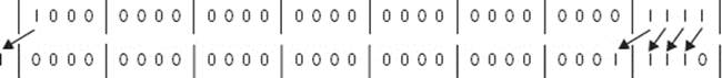
MOV r0, r0, #1 ; Multiply r0 by 2
LSL also enables you to do more complicated multiplications, which would take up more time using other instructions:
ADD r0, r0, r0, #3 ; Multiply r0 by 9 (r0 = r0 + r0 * 8)
RSB r1, r1, r1, #4 ; Multiply r1 by 15 (r1 = r1 * 16 – r1)
Another trick is to use shifts to create a number that cannot be expressed as an immediate number:
MOV r0, #0
MOV r1, #0x80000004
MOVS r0, r1, LSL #1
This command “moves” the value of r1 into r0, after performing a left shift on the value of r1. The value of r1 is still 0x80000004, but the ARM CPU read in the value of r1 shifted it left one space (the value now being 0x00000008), set the carry bit, and put the result into r0.
LSR
LSR (Logical Shift Right) is just like LSL. LSR is a shift operation and is equivalent to dividing by 2n. It is the equivalent to >> in C. It shifts the value right by the specified amount, padding with zeros.
MOV r0, r0, LSR #2 ; Divide r0 by 4
ASR
ASR (Arithmetic Shift Right) is just like LSR: it shifts a number right, the equivalent of dividing by 2n, but without rounding. The difference with LSR is that ASR keeps the signed bit, the first bit of a 32-bit number, and pads the result. If the number starts with a binary 0, it is padded with 0s. If it starts with a binary 1, the result is padded with 1s.
MVN r0, #0 ; r0 = 0xFFFFFFFF
MOV r1, r0, asr #16 ; r1 = 0xFFFFFFFF
MOV r2, r0, lsr #16 ; r2 = 0x0000FFFF
ROR
ROR (Rotate Right) rotates a number. Bits moved out of the right end of the register are rotated back into the left end.
MOV r0, r0, ROR #16 ; Swap the top and bottom halves of a 32-bit number
RRX
RRX (Rotate Right Extended) is just like ROR but with a crucial difference. ROR works with a register but also with the Carry flag. In essence, it performs a shift on a 33-bit number; the C flag is copied into the result before continuing the shift operation.
STACK OPERATIONS
Stack operations are essential for any program that calls subroutines or any program that deals with large amounts of data. Stack operations are like movement instructions but with added functionality that makes them extremely easy to use.
Traditionally, a stack grows down in memory, meaning that the last “pushed” value will be at the lowest address. ARM also supports ascending stacks using LDM and STM, meaning that the stack structure grows up through memory.
PUSH and POP operations are synonyms for STMBD and LDMIA, respectively, with the base register fixed as r13. However, because LDM and STM are not stack-specific, it is necessary to specify the stack pointer.
In ARM state, the core uses LDM and STM for stack operations. See the “Multiple Register Data Transfer” for more information.
PUSH
The PUSH instruction is actually a synonym for STMDB, using SP as the base register. This means that the stack pointer is decreased by 4 and is updated before the push operation occurs.
POP
Just like PUSH, POP is actually a synonym, this time for the LDMIA instruction. The stack pointer is again used automatically and is incremented by 4 after the pop operation.
In Thumb state, PUSH and POP are the only stack operations available.
Example: Returning from a Subroutine
subroutine PUSH {r5-r7,lr} ; Push work registers and lr
; code
BL somewhere_else
; code
POP {r5-r7,pc} ; Pop work registers and pc
COPROCESSOR INSTRUCTIONS
The CP15 coprocessor is a powerful tool, one that can help you greatly in your work. The CP15 can be programmed to configure cache, tightly coupled memory, system performance monitoring, and other systems. Architecturally, the CP15, and indeed any and all coprocessors available on the system, are not directly accessible; there are specific instructions to read and to write from coprocessors. If no coprocessors can execute a coprocessor instruction, an undefined instruction abort is generated.
Coprocessor instructions are complicated and require specific documentation from ARM (if using the CP15) or from the manufacturer if using another coprocessor. Do not be worried by their complexity; it is not necessary to know every opcode by heart, but it is important to understand what the instruction intends to do.
Physical coprocessor support was removed from ARM processors n ARMv7. The ARM11 family were the last cores to support external coprocessors. In order to maintain binary compatibility, coprocessor instructions still exist but are mapped directly to system instructions.
The original Thumb instruction set cannot access coprocessors, and therefore, these instructions do not work in Thumb state on processors which do not support Thumb-2. Thumb-2 added coprocessor support.
MRC
MRC (Move to ARM Registers from Coprocessor) has this structure:
MRC[condition] coproc, opcode1, dest, cpsource, cpreg[, opcode2]
This structure is slightly different from other ARM instructions:
condition is one of the 16 condition codes.
coproc is the name of the coprocessor (p0 to p15).
opcode1 is a coprocessor-specific opcode.
dest is the destination register.
cpsource is the source coprocessor register.
cpreg is the additional coprocessor register.
cpopcode2 is an optional coprocessor cpname operation.
For example:
MRC p15, 0, r0, c0, c0, 0
In this example, the instruction takes a register from CP15 (p15) and places the result into r0. It requests information from CP15’s c0 register, and the opcode2 specifies the subregister. This sounds complicated, and indeed it is complicated to read, but this specific instruction comes straight from ARM’s website on CP15. It is the instruction required to read the Main ID Register from CP15.
MCR
MCR (Move to Coprocessor from ARM Registers) has this structure:
MRC[condition] coproc, opcode1, dest, cpsource, cpreg[, opcode2]
MRC uses the same format at MCR, only the memory transfer direction changes. For example:
MCR p15, 0, r0, c13, c0, 3; Write Thread ID Registers
This example is, again, cryptic. This particular instruction is copying the value of r0 into the CP15 (p15), into c13. c13 on an ARM11 core is the thread ID register. By issuing this instruction, the ARM core will be given the thread ID for a particular thread, and the opcode2 tells the core that the thread ID number is user readable but needs privileged access to write a new value.
MISCELLANEOUS INSTRUCTIONS
The following are a few instructions that do not belong in any of the previous categories, but are in their own category.
SVC
SVC{cond} #immed
SVC (Supervisor Call) is an instruction that causes an exception. By issuing this instruction, the processor switches to supervisor mode, the CPSR is saved, and the execution branches to the SVC vector.
SVC can also take an immediate value but is not used by the processor. Instead, an SVC handler can be programmed to recover the value hard-coded into the instruction. In ARM state, this value is a 24-bit immediate value; in Thumb, it is an 8-bit immediate.
SVC used to be called SWI. Some compilers and decompilers still use the SWI name, but newer versions should use SVC.
NOP
NOP{cond}
NOP is short for No Operation, and put simply, it does nothing. It can be used to make an empty instruction before padding further instructions to a 64-bit boundary, or in some cases used as a handy point to put a breakpoint. In the past, NOP was sometimes used to force the processor to wait for one cycle, but with modern pipelines, this is no longer the case.
MRS
MRS{cond} Rd, psr
MRS (Move to ARM Register from System coprocessor) moves the content of a PSR to a general purpose register. This instruction is especially useful with saturated arithmetic because it is not possible to get the status of the Q flag directly. By using this instruction, you can get all flags and know if an instruction saturated.
MSR
MSR{cond} APSR_flags, Rm
MSR (Move to System coprocessor register from ARM Register) loads an immediate value, or the contents of a register, into the specified fields of the Program Status Register (PSR).
SUMMARY
This chapter presented a few of the most common ARM assembly instructions written in UAL, and how they are used. You learned about assembly and understanding instructions when decompiling and debugging. However, this is not a complete list of instructions since every core may have additional instructions added by the manufacturer.
Chapter 5, “First Steps”, explains debugging, shows several debugging examples, and discusses just how important it is to read basic assembly.
In the next chapter, you see the NEON processors, which is ARM’s advanced single instruction multiple data engine, capable of complex instructions for Digital signal processing and number crunching.
All materials on the site are licensed Creative Commons Attribution-Sharealike 3.0 Unported CC BY-SA 3.0 & GNU Free Documentation License (GFDL)
If you are the copyright holder of any material contained on our site and intend to remove it, please contact our site administrator for approval.
© 2016-2026 All site design rights belong to S.Y.A.