Professional Embedded ARM Development (2014)
Part I. ARM Systems and Development
Chapter 8. NEON
WHAT’S IN THIS CHAPTER?
Presenting NEON
Understanding NEON’s registers
Introducing some NEON instructions
Writing a NEON application in assembly
Using NEON intrinsics in C
Writing a NEON application in C
When ARM first released its original SIMD extensions, it was a huge success. Finally, single instructions worked on multiple data values accelerating multimedia applications, and enabling ARM cores access to a whole range of multimedia devices. Single instructions operating on multiple data values packed into registers meant that ARM cores could be used in DSP applications, or simply to obtain better performance. Mobile telephones could decode MP3 music using even less power, meaning longer battery life.
NEON is an extension of the original SIMD instruction set and is often referred to as the Advanced SIMD Extensions. It extends the SIMD concept by adding instructions that work on 64-bit registers (D for double word) and 128-bit registers (Q for quad word).
NEON instructions are executed as part of the ARM instruction stream, simplifying development and debugging.
WHAT ARE THE ADVANTAGES OF NEON?
NEON isn’t just about having huge amount of registers. The advantage of SIMD instructions is to execute an operation on several data values packed into a single register in a single instruction, but the data must first be correctly placed into the registers. How exactly is that done?
For example, consider a 24-bit image. There are three channels comprising a total of 24-bits per pixel: 8-bits for red, 8-bits for green, and 8-bits for blue. This is a repetitive structure, one such 24-bit structure per pixel and some digital cameras can make a lot of pixels.
Before doing anything interesting to the image, the data must first be loaded into registers. Without NEON, the operation would possibly have been to load the red component into r5, the blue component into r6, and the green component into r7, after which a filter would be applied, and the three registers would be written back with three reads, at least three operations, and finally three writes, for only one pixel. NEON has a different approach.
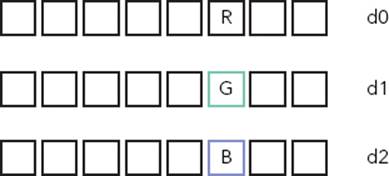
NEON registers are 64-bits wide, but you can load several 8-bit values into one register. Presume that the address of the first byte of data is held in r0. Using a NEON instruction, you can load 8 pixels into memory, using one instruction:
vld1.8 {d0, d1, d2}, [r0]
VLD is the NEON instruction to load data. VLD1.8 means that the processor will be loading 8-bit values, without interleaving. Three registers are also specified, so these three registers will be filled with 8-bit values. Finally, the address of the first byte is taken from a register; in this case, r0. Figure 8-1 shows the result of this operation.
FIGURE 8-1: Loading RGB data with a linear load
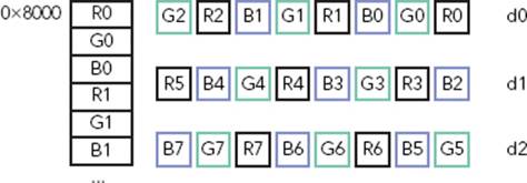
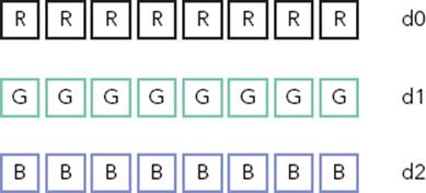
In one single instruction, 8 pixels have been loaded into three registers. However, any calculation might be complicated because the different colors have been loaded directly, or linearly. This is where interleaving comes in; the exact order of the data can be specified. By using an interleave of 3, the processor knows that each element is to be loaded, and the first will be placed into the first register, the second into the second, and the third into the third. When reading the fourth element, it will “loop,” putting it into the next free space in the first register, and repeating the process.
By rewriting the instruction and specifying an interleave of 3, Figure 8-2 shows the result.
FIGURE 8-2: Loading RGB data with a structured load
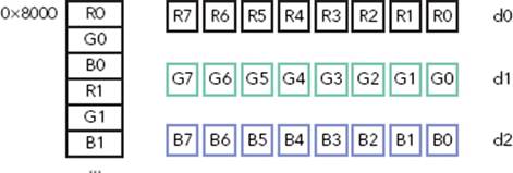
vld3.8 {d0, d1, d2}, [r0]
The data has now been loaded but this time into a format that is much easier to work with. No more shifting or masking to get the data you want; each color is put directly into one register. Of course, if the data were read in a certain way, the processor can also write data out in the same way.
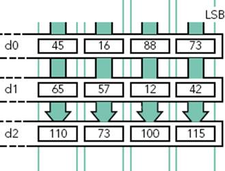
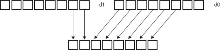
This brings a question: Because there is now a 64-bit register filled with 8-bit values, how is it possible to do any calculation? The answer is NEON’s lanes. A lane is a segment of a register, so one instruction can work on multiple values packed into a standard register. In this case, a lane could be 8-bits wide; therefore any calculation wouldn’t be done on the entire contents of the register but a series of 8-bit values. Figure 8-3 shows lane calculation on two D registers.
FIGURE 8-3: Lane operation on NEON registers
From here, virtually anything is possible. With one single instruction, you can swap two colors. You can do a weighted average of the three colors to create a fourth; effectively grayscaling the image. And when everything is finished, you can also use NEON to accelerate JPEG compression.
WHAT DATA TYPES DOES NEON SUPPORT?
NEON instructions support 8-bit, 16-bit, 32-bit, and 64-bit signed and unsigned integers; the same data can be found inside any ARM program. NEON also supports 32-bit single precision floating point numbers, and 8-bit and 16-bit polynomials.
Data types are specified by a letter, and any of the following are supported:
U for unsigned integer
S for signed integer
I for integer of unspecified type
F for single-precision floating-point number
P for polynomial
USING NEON IN ASSEMBLY
Before using NEON in higher level languages like C, you must understand the internals; how NEON reads in data, what sort of data, the instructions that can be used, and how NEON writes the data out to system memory.
Presenting the Registers
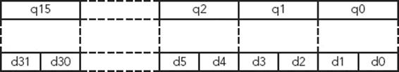
NEON has a huge amount of registers: 32 64-bit registers named d0 to d31. They also have another name; they can be seen as 16 128-bit registers named q0 to q15. Actually, they are the same registers; two D (double-word) registers map to one Q (quad-word) register. Figure 8-4 shows the relation between a Q register and two D registers.
FIGURE 8-4: Q registers and D registers
The registers are also shared with the VFP if one is present.
Why Are the Q and D Registers the Same?
A Q register is effectively two D registers, and filling a Q register overwrites the data in the two D registers. There are several reasons why both names exist, and one of them is that NEON instructions can widen the size of lanes. For example, when multiplying a 16-bit number by another 16-bit number, it is often useful to store the result in a 32-bit number. By using two D-registers to hold 16-bit values, there will be four lanes, or four 16-bit elements. When outputting four 32-bit numbers, the result must be placed into a Q-register, capable of four 32-bit lanes.
The inverse is also true; some NEON instructions can reduce the size of a result, in which case the operands is in a Q register, and the result is placed in a D register.
Loading and Storing Data
Just like the rest of an ARM core, NEON uses a load and store architecture. Data must be loaded into registers before doing any calculation.
There is only one instruction for loading data into NEON registers, and one instruction to save NEON registers back into memory, but the syntax enables a huge amount of customization.
The syntax of the instruction follows:
Vopn{cond}. datatype list, [rn]{!}
Vopn{cond}. datatype list, [rn], Rm
The structure consists of five parts:
The instruction mnemonic, either VLD for loads or VST for stores
The interleave pattern, the gap between elements
The number of bits of accessed data
A set of NEON registers to load/save data
An ARM register containing the memory location
Understanding the Different Interleaves
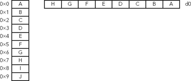
The interleave pattern specifies the separation of the data to be either read or written. Interleave 1 (for example, VLD1) is the simplest form. Data is handled sequentially, each element being placed one after another. This is used for loading one-dimensional arrays. Figure 8-5 presents an example of Interleave 1.
FIGURE 8-5: Interleave 1 example
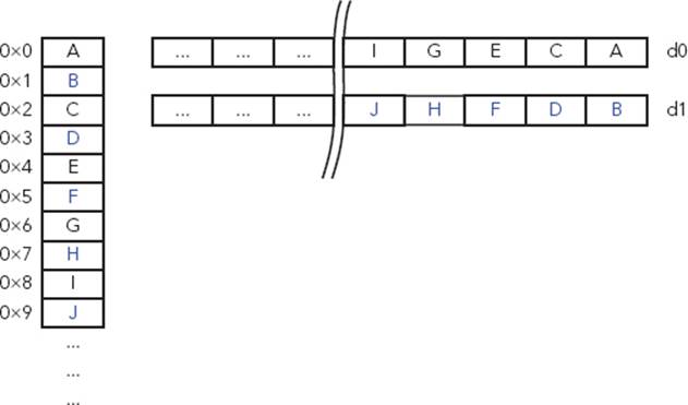
With interleave 2, (VLD2), the data is separated into two parts. For example, it can be used on an audio stream, separating data from the left and right channels. Figure 8-6 presents an example of Interleave 2.
FIGURE 8-6: Interleave 2 example
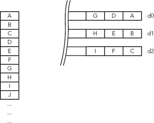
Interleave 3 uses three registers and can be used for three-dimensional arrays, for example, loading a graphics image coded in RGB. Figure 8-7 presents an example of Interleave 3.
FIGURE 8-7: Interleave 3 example
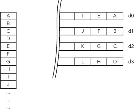
Interleave 4 uses four registers and can be used for four-dimensional arrays, much like the data found in ARGB images. Figure 8-8 presents an example of Interleave 4.
FIGURE 8-8: Interleave 4 example
Selecting the Data Size
You must specify the size of each data element. For a 24-bit graphics file, each pixel color must be coded in 8 bits. By specifying 8 bits in the instruction, the NEON engine knows to interleave on the next occurrence of that data size, effectively separating the pixel data.
Valid data sizes are 8-bits, 16-bits, or 32-bits.
To read 8-bit data with interleave 3, the instruction would be VLD3.8. To save 16-bit data with interleave 4, the instruction would be VST4.16. Lane size can increase or decrease with several operations, and you must take care to specify the correct width.
Defining the NEON Registers
You can define up to four registers depending on the interleave selected. For interleave 4, you must specify four registers because data will be separated into four different registers. For interleave 3, only specify three registers because data will be separated into three groups. For interleave 2, you can specify either two or four registers, depending on the length of the data to be read. For interleave 1, you can specify up to four registers.
Using default values, the ARM core can fill in all the register, using as many elements as possible. It is, however, possible to fill in a single element into one specific lane or to load a single element into all lanes. To do this, the lane must be specified after the register, in brackets. In the previous example, to load a single element into all lanes, use the following:
VLD3.8 {d0[2], d1[2], d2[2]}, [r0]
By issuing this instruction, the ARM core loads three 8-bit elements into lane 2 of d0, d1, and d2, effectively loading a single pixel into a specific location, as shown in Figure 8-9.
FIGURE 8-9: Inserting a single element into NEON registers
You can also load in a single element into every lane, by leaving out the lane parameter, for example:
VLD3.8 {d0[], d1[], d2[]}, [r0]
In Figure 8-10, the same 8-bit elements are loaded into all lanes of the registers.
FIGURE 8-10: Duplicating a single element into NEON registers
Vector Sizes
D registers are 64-bits wide, and Q registers are 128-bits wide, but what happens if the data inside the register is too small? In the previous example, eight 8-bit values were loaded into a D register, but what happens if only 6 values are available?
NEON can perform only full register operations, and with the exception of loading a single value into a lane or a register, all instructions execute the same operation on all lanes, including load and save operations. In most cases, this will be transparent; the final two results would give corrupted data because there was no valid input. So long as there is enough system memory free when the write operation occurs, this should not impact your program.
Effective Addressing
You can specify the address for operations in several ways. The simplest form is to specify the address of the memory in an ARM register, without any options. In this case, the data is read in (or written out), and the ARM register is not updated. You can use this on a system where a portion of memory is frequently updated.
Where data is written sequentially over large memory portions, you can use post-increment addressing. Just like on standard ARM instructions, the value of the ARM register can be updated after the memory operation by the amount of memory used, effectively updating the contents of the ARM register to point to the next portion of memory to be read/written. In the example of a graphics image, this would allow the processor to read in all the data sequentially.
VLD3.8 {d0-d2}, [r0]! ; update r0 after the data read
This doesn’t always suffice. The previous example shows how to read in data sequentially, but sometimes more complicated instructions are required. Sometimes, data will not be read in sequentially, but in blocks, for example, a program that will not read in each pixel of a line, but rather the first 8 pixels of each line. In this case, the program would need to read in 8 pixels, and then “jump” to the next line. This is where post-indexing comes in. After memory access, the pointer is incremented by a specific value held in an ARM register.
VLD3.8 {d0-d2}, [r0], #40 ; Increase r0 by 40 after the data read
Optimized memcpy
Embedded systems often spend a considerable amount of time copying memory from one location to another. With cost constraints, it’s not surprising that the system memory on an embedded system is often not the fastest available. Therefore, it is important to develop a fast method for memcpy.
The memcpy routine can change greatly between two systems, but for an ARM embedded system where NEON is present, it is often more effective to use NEON.
Here is a short example of using NEON to replace memcpy:
NEONcpy:
VLDM r1!, {d0-d7}
VSTM r0!, {d0-d7}
SUBS r2, r2, #0x40
BGE NEONcpy
In this example, r0 holds the source address, r1 holds the destination address, and r2 holds the amount of bytes to copy. Surprisingly, this does not create the speed boost that you would expect. It does, however, have a few advantages. For one, it can be done with minimal instructions and does not overwrite any of the ARM registers; no PUSH and POP required. Secondly, some cores can be configured so that NEON instructions allocate only level-2 cache, therefore not overwriting anything present in level-1 cache. This example is easy to optimize. By adding a simple preload instruction before the reads, the code becomes the following:
NEONcpy:
PLD [r1, #0xC0]
VLDM r1!, {d0-d7}
VSTM r0!, {d0-d7}
SUBS r2, r2, #0x40
BGE NEONcpy
In this instruction, the preload instruction prompts the processor to attempt to fill in a cache line with the data at the address in r0, but only if the system has the required bandwidth. It does not guarantee that cache lines will be filled, but if they are, subsequent VLDM instructions will result in a cache hit, greatly increasing speed. In tests, this technique showed greatly improved throughput without modifying level one cache lines or ARM registers.
NEON Instructions
NEON instructions can be divided into different categories: arithmetic, logical operations, conversion, shifting, and other advanced features.
Arithmetic
ARM assembly instructions have multiple instructions for arithmetic, for example, adding two numbers, adding with accumulate, and so on. NEON goes a step further, introducing new and advanced instructions. NEON can simply add or subtract, but also add and narrow the high half of an integer, add two numbers dividing the result by two, or execute a pair-wise add, to name but a few.
Multiplication has also been revisited, and new commands exist to automatically double the results of a multiplication or Vector Fused Multiply and Accumulate.
Comparison
NEON benefits from multiple comparison instructions, and the comparison can be a simple bitwise comparison, comparing with another register, extracting maximum/minimum values from a pair of registers, and so on.
General Data Processing
General data processing routines include the possibility to change from one data type to another. For example, it is possible to convert floating-point numbers into integer, and vice versa. NEON also has something called vector extraction (Figure 8-11), extracting 8-bit elements from the bottom end of the second operand vector and the top end of the first, concatenating them, and placing them in the destination vector.
FIGURE 8-11: Vector extract
NEON can also reverse the order of 8, 16, or 32-bit elements within a vector, using the VREV instructions. This can be used to change endianness, or to rearrange components or channels of stream data.
NEON also proposes something that is missing from ARM assembly, the possibility to swap two registers without needing a third register as a temporary store.
NOTE This is only a small list of NEON data processing instructions. More instructions are listed in Appendix D.
USING NEON IN C
Just like with ARM Assembly, NEON assembly can make some heavily optimized code at the cost of spending more time writing code. Writing code in C means faster development time and more maintainable code, and compilers normally do a good job of optimizing code. Sometimes, it is necessary to turn to assembly for finely tuned performance, but in most cases, the use of C gives good performance, noticeably better than hand coding using ARM instructions (which are already fast).
A compiler cannot take standard code and use NEON instructions, even if there are many loops, or in cases in which NEON could accelerate code. The compiler has to be specifically told to use the NEON engine. There are several ways to do this as described here.
Presenting Intrinsics
Intrinsic functions and data types, or intrinsics, provide a direct link to assembly, while maintaining higher level functions such as type checking and automatic register allocation. This enables elegant C functions, maintaining the readability and maintainability of C, without the need to write direct assembly instructions. To use NEON intrinsics, include the header file arm_neon.h.
Vector Data Types
C intrinsics enables defining any sort of data type accepted by NEON. NEON data types are names according to this pattern:
<type><size>x<number of lanes>_t
The type can be an int, uint, float, or poly. The size is the size of each lane, and the number of lanes defines how many lanes will be loaded, and therefore the type of register used (D or Q). To load a series of pixels into a 64-bit D register, each pixel being an 8-bit unsigned value, chooseuint8x8_t. The entire list of supported datatypes is presented in Appendix D, “NEON Intrinsics and Instructions.”
Loading a Single Vector from Memory
To load data into a NEON register, intrinsics have been made that resemble assembly, but add data types to help compiler checking. They return the data type that the register(s) can hold. To load a single vector, an intrinsic is used that uses the memory address as an argument and returns the data type contained in the register.
// VLD1.8 {d0, d1}, [r0]
uint8x16_t vld1q_u8(__transfersize(16) uint8_t const * ptr);
// VLD1.16 {d0, d1}, [r0]
uint16x8_t vld1q_u16(__transfersize(8) uint16_t const * ptr);
// VLD1.32 {d0, d1}, [r0]
uint32x4_t vld1q_u32(__transfersize(4) uint32_t const * ptr);
// VLD1.64 {d0, d1}, [r0]
uint64x2_t vld1q_u64(__transfersize(2) uint64_t const * ptr);
// VLD1.8 {d0, d1}, [r0]
int8x16_t vld1q_s8(__transfersize(16) int8_t const * ptr);
// VLD1.16 {d0, d1}, [r0]
int16x8_t vld1q_s16(__transfersize(8) int16_t const * ptr);
// VLD1.32 {d0, d1}, [r0]
int32x4_t vld1q_s32(__transfersize(4) int32_t const * ptr);
// VLD1.64 {d0, d1}, [r0]
int64x2_t vld1q_s64(__transfersize(2) int64_t const * ptr);
// VLD1.16 {d0, d1}, [r0]
float16x8_t vld1q_f16(__transfersize(8) __fp16 const * ptr);
// VLD1.32 {d0, d1}, [r0]
float32x4_t vld1q_f32(__transfersize(4) float32_t const * ptr);
// VLD1.8 {d0, d1}, [r0]
poly8x16_t vld1q_p8(__transfersize(16) poly8_t const * ptr);
// VLD1.16 {d0, d1}, [r0]
poly16x8_t vld1q_p16(__transfersize(8) poly16_t const * ptr);
// VLD1.8 {d0}, [r0]
uint8x8_t vld1_u8(__transfersize(8) uint8_t const * ptr);
// VLD1.16 {d0}, [r0]
uint16x4_t vld1_u16(__transfersize(4) uint16_t const * ptr);
// VLD1.32 {d0}, [r0]
uint32x2_t vld1_u32(__transfersize(2) uint32_t const * ptr);
// VLD1.64 {d0}, [r0]
uint64x1_t vld1_u64(__transfersize(1) uint64_t const * ptr);
// VLD1.8 {d0}, [r0]
int8x8_t vld1_s8(__transfersize(8) int8_t const * ptr);
// VLD1.16 {d0}, [r0]
int16x4_t vld1_s16(__transfersize(4) int16_t const * ptr);
// VLD1.32 {d0}, [r0]
int32x2_t vld1_s32(__transfersize(2) int32_t const * ptr);
// VLD1.64 {d0}, [r0]
int64x1_t vld1_s64(__transfersize(1) int64_t const * ptr);
// VLD1.16 {d0}, [r0]
float16x4_t vld1_f16(__transfersize(4) __fp16 const * ptr);
// VLD1.32 {d0}, [r0]
float32x2_t vld1_f32(__transfersize(2) float32_t const * ptr);
// VLD1.8 {d0}, [r0]
poly8x8_t vld1_p8(__transfersize(8) poly8_t const * ptr);
// VLD1.16 {d0}, [r0]
poly16x4_t vld1_p16(__transfersize(4) poly16_t const * ptr);
Loading Multiple Vectors from Memory
Loading multiple vectors from memory is just like loading a single vector, except that the interleave must be specified. The instructions are almost identical to single instructions; the memory pointer is passed as an argument, and the resulting data type is returned. The interleave is defined in the instruction.
uint8x8_t data vld1_u8(src); //Loads one d-word register
uint8x8x2_t data2 vld2_u8(src); //Loads two d-word registers, using interleave 2
uint8x8x3_t data2 vld3_u8(src); //Loads three d-word registers, interleave 3
In each case, the instruction resembles the assembly layout.
Using NEON Intrinsics
NEON intrinsics are well designed; they are easily accessible from C without any major change. So long as the logical procedure is respected, read in data using intrinsics, execute NEON instructions, and then write data out, again using intrinsics. Then the routine can benefit from NEON optimization.
It is possible to mix ARM and NEON instructions, but there is sometimes a penalty in doing so; NEON can only use NEON registers, just as ARM can only use ARM instructions. Registers will need to be transferred to and from the NEON engine, costing a slight overhead.
You can also create portions of code that execute only if a NEON engine is present (and defined), by using #ifdef sections.
#ifdef __ARM_NEON__
// NEON code
#else
// ARM code
#endif
By using this system, you can generate source code that is easily portable from one processor design to another using standard C.
Converting an Image to Grayscale
On almost any modern digital camera, there is an option to convert images to grayscale. This operation is simple; it takes the red, green, and blue components, calculates a weighted average, and then writes the result to a new pixel. This is the sort of repetitive calculation that NEON is well suited for. To do that, following is an example application.
First, a little understanding about the way our eyes see the world. Human eyes are more adapted to seeing green than any other color, so when changing an image to grayscale, simply adding the red, green, and blue component, and then dividing by three is not enough. For clear grayscale images, a certain amount of weight is added to each color. This is known as the luminosity method. It is common to multiply the red channel by 77, the green channel by 151 and the blue channel by 28. The sum of these three numbers is 256, making division simple.
To do that, the program can fill three registers with specific values, the weight ratio. The application must read in a series of pixels, separating the red, green, and blue components into separate registers using interleaving. Next, each color component is multiplied by the weight ratio, and the result is placed into another register. Finally, the new registers are added into a single register, divided, and then written back out into memory. The end result is ((rx) + (gy) + (bz)) / (x + y + z).
First, three registers need to be filled with 8-bit values, the ratio values. There are three registers: one for the red components, one for the green, and one for the blue. To take one 8-bit value and to repeat that value over the NEON register, the VDUP instruction is used.
uint8x8_t r_ratio = vdup_n_u8(77);
uint8x8_t g ratio = vdup_n_u8(151);
uint8x8_t b ratio = vdup_n_u8(28);
Note that in C, it is not necessary to specify a register; the compiler can do this automatically and keep track of which variable is held in which register. Now, the data has to be read in, using interleave 3. The variable rgb is defined as a uint8x8x3_t because it uses three registers.
uint8x8x3_t rgb = vld3_u8(src);
vld3_u8 does a vector load of unsigned 8-bit values, using interleave 3. Again, you do not need to specify the registers. Now comes the tricky part. Each pixel is 8 bits in size, but you must multiply each one, and add the results of three multiplications together. It isn’t possible to do this in an 8-bit lane because there will almost certainly be a data loss. The reason why this example uses only a 64-bit register instead of a 128-bit register is for this reason: The program must widen the lanes from 8-bit to 16-bit and therefore use a larger output register.
Therefore, a temporary register is defined as such:
uint16x8_t temp;
This reserves a Q register for a total of 8 16-bit variables. Now, multiply the R component by the ratio, and save it into the temporary register.
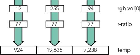
temp = vmull_u8(rgb.val[0], r_ratio);
This instruction is a Vector Multiply, which tells NEON to multiply each lane in rgb.val[0] (the red component of each pixel) by r_ratio (the weight ratio) and to put the results into temp. Because the instruction is VMULL with two L’s, it also widens the lane from 8 bits to 16 bits. An example can be seen in Figure 8-12.
FIGURE 8-12: VMULL multiplying 8-bit values into a 16-bit value
The variable temp now contains each red component of the 8 pixels, multiplied by the red weight. You can do the same thing with the green and blue components: Multiply them into separate registers and then add the results. However, NEON has a more elegant solution: Multiply and Accumulate.
temp = vmlal_u8(temp, rgb.val[1], g_ratio);
Vector Multiply and Accumulate Long (VMLAL) is the same as Vector Multiply, except it enables adding a value to the result of the multiplication. In this case, VMLAL can multiply the green component of each pixel by the green weight ratio and then add the existing values in temp before writing the data back into temp. Now the variable temp contains the weighted red components plus the weighted green components. All that is left to do is to do the same action with the blue components.
temp = vmlal_u8(temp, rgb.val[2], b_ratio);
Now temp contains the weighted value of each component of the pixel, multiplied by 256. The value 256 wasn’t chosen randomly. The value was chosen because it is a power of 2 and can be shifted to perform a fast division. Also, the largest value possible in an 8-bit value is 256, and the largest possible value of all the weighted values times the pixel components is 65536, the maximum size of a 16-bit value; so there will never be any data loss, even for the highest values possible. Now each weighted pixel must be divided by 256 by shifting and then output the results into 8-bit values. This is a job for VSHRN.
result = vshrn_n_u16(temp, 8);
Vector Shift Right, Narrow (VSHRN) is an instruction that can take a quad-word register, perform a division by a power of 2, and then output the results into a double-word register, narrowing the lanes. Now you have to write the results back out into memory.
vst1_u8(dest, result);
And that’s it! A simple C function that loops for each 8 pixels of an image and automatically converts RGB pixels into grayscale. The entire C routine looks like this:
void neon_grayscale(uint8_t * dest, uint8_t * src, int num)
{
int i;
uint8x8_t r_ratio = vdup_n_u8(#77);
uint8x8_t g_ratio = vdup_n_u8(#151);
uint8x8_t b_ratio = vdup_n_u8(#28);
num/=8; //NEON will work on 8 pixels a time
for (i=0; i<n; i++)
{
uint16x8_t temp;
uint8x8x3_t rgb = vld3_u8(src);
uint8x8_t result;
temp = vmull_u8(rgb.val[0], r_ratio);
temp = vmlal_u8(temp,rgb.val[1], g_ratio);
temp = vmlal_u8(temp,rgb.val[2], b_ratio);
result = vshrn_n_u16(temp, 8);
vst1_u8(dest, result);
src += 8*3; // 3 x 8 pixels in RGB format
dest += 8; // One single 8-bit value per pixel
}
SUMMARY
In this chapter, you have seen an overview of the NEON architecture and how it augments ARM’s original SIMD instructions. You have seen how to load data into NEON registers, and the different interleave options available. I have shown an example NEON program written directly in C, using NEON intrinsics, and just how easy it is to use the NEON engine from C.
In the next chapter, I will talk about debugging, and software and hardware debuggers, and present some of the techniques available to debug programs and low-level code.
All materials on the site are licensed Creative Commons Attribution-Sharealike 3.0 Unported CC BY-SA 3.0 & GNU Free Documentation License (GFDL)
If you are the copyright holder of any material contained on our site and intend to remove it, please contact our site administrator for approval.
© 2016-2026 All site design rights belong to S.Y.A.