Make: AVR Programming (2014)
Part II. Intermediate AVR
This section makes you a more efficient programmer of the chip and expands the universe of what you’ll think an AVR can do. You’ll start doing cool things with the internal hardware peripherals and some more sophisticated tricks in firmware using what you already know. This section provides the big payoff—the tools to do things with a bare AVR chip that you just can’t do without knowing a little about how the hardware works.
Mastery of microcontrollers starts with good use of the interrupt system. Chapter 8 shows you how to allow events in the outside world to directly and instantaneously call portions of your code. You’ll use this speed to build a noncontact capacitive touch sensor out of aluminum foil and tape that will detect your finger as far as a few centimeters away.
Chapter 9 introduces you to the three internal timers that the ATmega microcontroller comes with. Offloading timing from your code to the timer/counter hardware lets you do things with a precision and speed that you couldn’t before, or even just to do two things at once. Timers are shockingly versatile, and you’ll use them to make a reaction timer, an improved square-wave organ, and even a tiny AM radio transmitter. What do these have in common? Time.
In Chapter 10, you finally get to output something other than ones and zeros from the AVR. (Sort of). Pulse-width modulation (PWM) is the most convenient way to dim LEDs and slow down motors. Between the timer and interrupt hardware, the AVR provides you with a few options for producing PWM, and we’ll go through three.
Servo motors are the perfect match for microcontrollers. For so little circuitry, you get so much movement. In Chapter 11, you’ll use the 16-bit timer to directly control a servo motor with almost no CPU overhead. The project for this chapter is a “sundial” in reverse—instead of the sun creating a moving shadow, you’ll track a laser across the ceiling to show the time. As a bonus, you also get to make a real-time clock out of the AVR.
Rounding out the intermediate section, in Chapter 12 I’ll show you two of my favorite mathematical techniques that help you get more out of the ADC: oversampling and exponential smoothing. These techniques let you build a 12-bit accurate voltmeter and a super-sensitive footstep detector built from a $2 piezo element.
Chapter 8. Hardware Interrupts
Real-time Response, and a Capacitive Sensor
This chapter introduces perhaps the most useful of the AVR’s hardware peripherals—the interrupt system. Up to now, our programs have been very much linear, going from one command to the next command to the next command. However, you often have to deal with input from the real world that arrives asynchronously, almost at random—you want the AVR to respond when you press the button, not when it’s ready to have you press the button.
In this chapter, we’ll take our first steps into interrupt programming. The first two examples will demonstrate how interrupts can run code for you any time an input pin changes state. And while it’s pretty cool to have the interrupt hardware directly run a bit of your code when a button is pressed, it’s a bit trivial. So we’ll expand on that and build a capacitative touch sensor. (In fact, if you build a large sensor and tweak the code, it’ll even detect your hand a centimeter or so away from the touch place.)
WHAT YOU NEED
In this chapter, in addition to the basic kit, you will need:
§ An LED or a few. You may still have these hooked up.
§ A pushbutton. You may still have this hooked up, too.
§ A capacitive touch sensor: we’ll make ours out of two pieces of aluminum foil, some tape, a piece of paper, two alligator clips, and a 100k ohm resistor.
§ A USB-Serial adapter.
Elegant and skillful use of the interrupt system separates good programmers from good microcontroller programmers. When you’re writing code that runs on a multitasking operating system, you don’t have to worry nearly as much about what happens when, or how long it takes. The OS takes care of the nitty-gritty details like making sure that the video card is constantly fed with video data and that the mouse and keyboard are being constantly listened to. (You don’t have to worry about it, because your OS is doing all this for you with its own system of hardware interrupts.)
Here in the land of microcontrollers, we don’t often have the luxury of running an OS. Instead, if we’d like to have two things going on seemingly at once, we either cycle between them very quickly or set up a system where one can preemptively interrupt the other. The first strategy, called “polling” in the comp sci jargon, can suffice for a lot of applications. The event loop in a polling-style program is essentially a list of things that we’d like to check up on. (Is a button pressed? If it is, light an LED.) The AVR then runs through that list repeatedly as fast as it can. If we keep our event loop short enough that any given part comes around frequently enough, it’s hard to tell that we’re polling—when a button is pressed, the LED seems to light up instantly even if we caught the program in another part of the event loop.
Polling code frequently looks something like this:
int main(void){
// Event Loop
while(1){
if (checkLightSensor()){
set_bit(LED_PORT, LED);
}
switchesState = checkSwitches();
if (switchesState == DANGER_VALUE){
turnOffKillerLaser();
}
doWhateverElse();
}
}
One problem with polling in event loops is that there’s no concept of priority. Even though we care more about the limit switches that control our laser than the light sensors, each separate check happens at the same frequency, once per trip through the event loop. That may work fine as long as the event loop is short enough. But if the doWhateverElse() routine takes a while, maybe because it uses a lot of CPU power, too much time can elapse between checks of the switches, and our death-laser-on-a-motor might end up cutting something that it shouldn’t.
Handling multiple jobs at once is where interrupts excel. Interrupts do just what they sound like—they interrupt the normal flow of the program. When an interrupt is triggered, all of the variables that you’re using are stashed in memory and then a special function, called an interrupt service routine (ISRs), is run. After the ISR is done, your program picks up again where it left off. Switching from one context to another like this takes an AVR chip four cycles (half a microsecond at 8 MHz) both going and returning, but otherwise the ISR happens just about instantly when the interrupt is flagged.
What are interrupts good for? There are internally triggered interrupts that respond to the internal AVR hardware peripherals. For instance, there are interrupts that can run ISR code when the analog-to-digital converter or USART has got new data or when the timer/counter peripheral has reached a certain value. Instead of waiting in a blocking loop until the peripheral is ready, we can write our ISR to handle that peripheral directly, and it will execute only when required. We’ll be using internally triggered interrupts throughout the rest of the book, and when I introduce a new peripheral subsystem, I’ll show you how it can trigger ISRs for you.
There are also externally triggered interrupts that can react to to a voltage change on any of the AVRs pins, and these external interrupts will be the focus of this chapter. Without interrupts, you have to check each button in the system to see if it’s pressed, which wastes some processor cycles and can result in serious delay if parts of the event loop take a long time. By using interrupts for each AVR pin, you can dispatch code that executes within a microsecond of the button press.
From a coder’s perspective, using interrupts judiciously can vastly streamline your work. For instance, when we wanted to test if a button had just been pressed, we had to store the old button state in a variable and check each time around the event loop to see if the current state is different from the old state. Then we had to replace the old state with the current one. By using interrupts, we can configure the interrupt routines to only fire when a pin changes state. (We still have to test whether it changed into a pressed or released state, but it’s a lot simpler.)
I find that interrupts often match the way I’m thinking about a coding problem. I want the AVR to be doing one or two main things, but be ready to drop them and execute a third task for a while if it needs to react to a change coming in from the outside world. Interrupts make it much easier for my code to mirror the way I think about the problem.
Interrupts are a deep and rich topic, and we’ll just be scratching the surface. That said, we’ve got a lot of surface area to scratch. In this chapter, we’ll walk through a few exercises with external interrupts, we’ll use internal interrupts paired with the timer/counter modules to create a system clocks, and then we’ll combine both types to implement a capacitive touch sensor.
External Interrupts 101: Real-time Button Pressing Examples
The first use case for external hardware interrupts is to handle a button press asynchronously. That is, you write your event loop so that when an interrupt comes in from outside, the CPU drops whatever it was doing and executes your interrupt routine before getting back to the event loop.
There are two flavors of external interrupts: the fancy interrupts, INT0 and INT1, and the pin-change interrupts. We’ve wired our button up to pin PD2, which is the dedicated pin for the INT0 interrupt, but which also works with the pin-change interrupt mechanism like all the other I/O pins on the AVR chips.
The INT0 interrupt mechanism has more versatile triggering possibilities, allowing you trigger the interrupt on a rising voltage, a falling voltage, any change, or continuously for a low-voltage level, which is useful for interaction with other processors or peripherals. Due to their hardware complexity, there are only two of these type interrupts: INT0 and INT1, on pins PD2 and PD3.
The PCINT system, on the other hand, allows you to treat every I/O pin on the AVR as an interrupt source if you so desire, but only detects changes (not their direction) and thus requires a little more processing to interpret. The pin-change interrupts are grouped together in banks, so it’s more accurate to say that there’s a pin-change interrupt for the “B” pins, one for the “C” pins, and one for the “D” pins. We use pin-mask registers to select which of the pins from within the bank we want to trigger the interrupt. I’ll discuss this more in the following code example.
External Interrupt 0 Example
First off, let’s consider the INT0 and INT1 external interrupts. These are the two highest-priority interrupts in the chip, so in general, you’ll want to reserve them for some signal that you really care about. (If you get a bunch of interrupts at the same time, the INT0routine will run before any of the others.)
As an example, I built a logging accelerometer with GPS, which was mainly an exercise in coordinating among three devices—the GPS over the USART, the accelerometer using I2C serial, and external flash memory using SPI serial. (I’ll cover the two advanced serial protocols in Chapter 16 and Chapter 17.)
The accelerometer (an LIS302D) updated at 100 Hz, so every 10 milliseconds, the AVR had to request new data from it or else it would miss the current value. Fortunately, the accelerometer provided a falling-voltage signal when it had new data ready. The simplest solution was to connect the data-ready signal from the accelerometer directly to pin PD2 on the AVR, and trigger an interrupt for a falling voltage. When the accelerometer had new data, it grounded the wire, the AVR detected the falling edge, triggered the interrupt, read the new data in, and saved it to memory. Easy peasy.
Many external peripherals will signal data-ready or otherwise demand your attention by either raising or lowering a voltage signal on a dedicated line, and that’s exactly the situation that INT0 and INT1 are designed to handle. For the moment, we’re simulating this all with a button press, so let’s look at some code.
The first demo interrupt program does two things. In the main event loop, the AVR blinks an LED, LED0, with a delay—a pretty boring main task. In the ISR, which is triggered by the INT0 state change interrupt, we turn on another LED depending on whether the button is pressed or not. Again, that’s pretty lame, but this is our first example with interrupts. Let’s see how it’s done in Example 8-1.
Example 8-1. helloInterrupt.c listing
/*
Demo of using interrupts for doing what they do best --
two things at once.
Flashes LED0 at a fixed rate, interrupting whenever button is pressed.
*/
// ------- Preamble -------- //
#include <avr/io.h>
#include <util/delay.h>
#include <avr/interrupt.h>
#include "pinDefines.h"
ISR(INT0_vect) { /* Run every time there is a change on button */
if (bit_is_set(BUTTON_PIN, BUTTON)) {
LED_PORT |= (1 << LED1);
}
else {
LED_PORT &= ~(1 << LED1);
}
}
void initInterrupt0(void) {
EIMSK |= (1 << INT0); /* enable INT0 */
EICRA |= (1 << ISC00); /* trigger when button changes */
sei(); /* set (global) interrupt enable bit */
}
int main(void) {
// -------- Inits --------- //
LED_DDR = 0xff; /* all LEDs active */
BUTTON_PORT |= (1 << BUTTON); /* pullup */
initInterrupt0();
// ------ Event loop ------ //
while (1) {
_delay_ms(200);
LED_PORT ^= (1 << LED0);
} /* End event loop */
return (0); /* This line is never reached */
}
As usual, let’s first skip down to the event loop and see what the main() routine does. At first glance, it looks like all it does is blink LED0 on and off again. There’s nothing in the event loop concerning the button or LED1 at all!
Before we leave the event loop, think about how you’d program something similar without interrupts. If you took the easy way and tested the button once per trip around the event loop, just before or after the _delay_ms() statement, you’d notice a delay between the time when you press the button and the time that LED1 lights up, right? For extra credit, try to code up this functionality as a polled event-loop type program—just comment out the initInterrupt0() function and test bit_is_set() to toggle LED1 from within the event loop. You’ll find that the button pressing action will start to feel horribly sluggish if it takes significant time to cycle through the event loop.
Let’s see what’s going on with the interrupts and LED1. First, there’s the ISR() call itself. If you’ve been following along, you’ll guess (correctly) that ISR being written in all-caps denotes a macro. (In this case, it’s a fairly complicated macro that defines a function, defined in the interrupt.h header file that we included at the top of the program.)
ISRs are special routines that run when their interrupt flag is set, and their interrupt vector is called. For the nitty-gritty on interrupts, see Interrupts: Under the Hood. Otherwise, feel free to think of the ISR as being a function that gets called whenever its interrupt flag is set.
THE ISR() IS A SPECIAL FUNCTION
ISRs are different from normal functions in two important ways, however. ISR() “functions” don’t have a return value, and they take only their interrupt vector as an argument. This means you can’t pass variables to the ISR directly and have to use variables with global scope to get data in and out of the ISR. For now, just remember that an ISR is a special type of macro/function hybrid that has neither arguments nor return values.
In this example, we’re setting the ISR for the INT0 interrupt, and so we use the special (macro) name INT0_vect. The interrupt macro names are defined in the normal io.h header file that’s specific for the chip. In our case, that’d be iomx8.h, which covers the entire series of Mega chips in the “x8” series like the ATmega48, ATmega88P, etc.
INTERRUPTS: UNDER THE HOOD
The interrupt system is a little bit involved at the hardware level, but it’s not magic, and knowing how it works may someday help you track down interrupt-related bugs.
Like everything else in the AVR, it’s all done with bits in registers. For each type of possible interrupt, there is a flag bit inside the AVR that can be set. When you press the button, the INT0 interrupt flag is set. There is also a global interrupt-enable bit that determines whether or not any interrupts are checked.
When this global flag is set, the AVR continually checks all of the interrupt flags to see if any of them are set. If one or more of the individual interrupt flags is set, the global interrupt-enable flag is first cleared, preventing any further interrupts, and then the system runs the ISR corresponding to the first individual flag it finds. When the first ISR is done, the system sets the global interrupt-enable flag again, and control either goes to the next ISR with a set flag or back to your main program where it left off. The ordering of the individual interrupt flags thus provides a priority scheme for executing the ISRs. (For the complete list, see Table 8-1, which is derived from a table from the datasheet.)
How does the interrupt mechanism know which section of code to run? At the very beginning of the machine-language version of your code lies the interrupt vector space. Each entry in this space contains a command to jump to the memory location where the corresponding ISR code will be stored. When the CPU gets a USART_RX interrupt, for instance, signaling that some data has come in over the USART, the USART_RX interrupt flag is set. Because this flag is the 18th flag in the interrupt table, the 18th entry in the interrupt vector table is read out. The data stored in the 18th slot of this table is the memory location where the ISR routine’s function starts.
In short, when an interrupt flag is thrown, the CPU drops what it’s doing, disables further interrupts by turning off the global interrupt bit, looks up the corresponding memory address in the interrupt vector table, and then starts running whatever code it finds at that memory address—which is set to be the beginning of your ISR. Each ISR then ends with the RETI (“return from interrupt”) command, which tells the CPU to turn the global interrupt flag back on, to re-check the interrupt flags register, and if none are set, to return to your code where it left off. If, while it was handling your first interrupt request, another interrupt flag has been set, the CPU handles the new interrupt before getting back to your main() routine.
What does all this mean for you as a programmer? Because the individual interrupt flags are prioritized, they’ll reliably be run in the same order. Think about this when designing your hardware layout, and physically connect the most important signals to the most important interrupt pins. Additionally, the individual interrupt flags can be set even when the global interrupt flag isn’t. Later on, when the global interrupt-enable flag is set, they’ll all get processed in the normal priority order. Because interrupts are handled one after the other, if your interrupt routines take a long time to run, or the interrupt flags keep getting set very frequently, execution may take a while before it can get back to your main routine. And finally, because the individual interrupt flags are just like any other flag in a hardware register, you can trigger them from within your own code if you ever need to simulate a button press or whatever.
Table 8-1. Interrupt vector
|
Name in datasheet |
Vector name for ISRs |
Interrupt definition |
|
RESET |
External Pin Reset, Power-on Reset, Brown-out Reset, and Watchdog System Reset |
|
|
INT0 |
INT0_vect |
External Interrupt Request 0 |
|
INT1 |
INT1_vect |
External Interrupt Request 1 |
|
PCINT0 |
PCINT0_vect |
Pin Change Interrupt Request 0 |
|
PCINT1 |
PCINT1_vect |
Pin Change Interrupt Request 1 |
|
PCINT2 |
PCINT2_vect |
Pin Change Interrupt Request 2 |
|
WDT |
WDT_vect |
Watchdog Time-out Interrupt |
|
TIMER2 COMPA |
TIMER2_COMPA_vect |
Timer/Counter2 Compare Match A |
|
TIMER2 COMPB |
TIMER2_COMPB_vect |
Timer/Counter2 Compare Match B |
|
TIMER2 OVF |
TIMER2_OVF_vect |
Timer/Counter2 Overflow |
|
TIMER1 CAPT |
TIMER1_CAPT_vect |
Timer/Counter1 Capture Event |
|
TIMER1 COMPA |
TIMER1_COMPA_vect |
Timer/Counter1 Compare Match A |
|
TIMER1 COMPB |
TIMER1_COMPB_vect |
Timer/Coutner1 Compare Match B |
|
TIMER1 OVF |
TIMER1_OVF_vect |
Timer/Counter1 Overflow |
|
TIMER0 COMPA |
TIMER0_COMPA_vect |
Timer/Counter0 Compare Match A |
|
TIMER0 COMPB |
TIMER0_COMPB_vect |
Timer/Counter0 Compare Match B |
|
TIMER0 OVF |
TIMER0_OVF_vect |
Timer/Counter0 Overflow |
|
SPI, STC |
SPI_STC_vect |
SPI Serial Transfer Complete |
|
USART, RX |
USART_RX_vect |
USART Rx Complete |
|
USART, UDRE |
USART_UDRE_vect |
USART, Data Register Empty |
|
USART, TX |
USART_TX_vect |
USART, Tx Complete |
|
ADC |
ADC_vect |
ADC Conversion Complete |
|
EE READY |
EE_READY_vect |
EEPROM Ready |
|
ANALOG COMP |
ANALOG_COMP_vect |
Analog Comparator |
|
TWI |
TWI_vect |
2-wire Serial Interface |
|
SPM READY |
SPM_READY_vect |
Store Program Memory Ready |
In our code, we’ve got an event loop that blinks an LED, and we’ve got an ISR() that handles our button presses; it is called when the INT0 interrupt is triggered. How do we configure the triggering?
With all interrupts, at least two flags need to be set: one to enable our particular interrupt and one to enable interrupts in general. This two-tiered system is terribly handy when you want to enable or disable all interrupts at once or singly, but it means that you have to remember to set at least two flags during initialization.
To follow along with the initInterrupt0() function, it may help to look at the datasheet chapter titled “External Interrupts,” and look in the “Register Description” section. Our initialization routine starts off by setting the INT0 bit in the Enable Interrupt Mask so that our specific interrupt will fire, then sets the bit that makes the interrupt trigger on any change in logical state. Why trigger on both changes? Because we’re using the ISR to turn the LED on and off, we need to trigger on both the rising and falling voltage edges. Finally, the initialization routine ends with a command that sets the global interrupt-enable bit, turning on all interrupts that we’ve configured so far: sei();.
Sometimes you’ll find that you need to turn on or off all interrupts at once. The AVR designers have anticipated this and added a global interrupt bit and two commands to control it. sei() turns all interrupts on, and cli() turns them all off. For some timing-sensitive sections of code, especially if you have long-running interrupt service routines, you may want to disable interrupts before you call critical functions and reenable interrupts after you return.
Both sei() and cli() compile into machine-language instructions of the same name, so we’re stuck with those names even though I don’t find them particularly descriptive. In case you’re wondering, “sei” is “Set Enable Interrupt” bit and “cli” is “CLear enable Interrupt” bit. (Hooray for inconsistent mnemonics!)
Also note that interrupts are automatically turned off when entering an ISR and turned back on again when finishing. This prevents a situation where an interrupt gets called from inside another interrupt, which itself had been called from inside another interrupt, and so on. Of course, if you’d like to have interruptable ISRs, you can specify that either manually by calling sei() in the ISR itself or by using a special ISR_NOBLOCK argument to the ISR() definition. Use this only if you know what you’re doing!
And don’t forget that interrupts are disabled by default, and that you need to explicitly enable them with an sei() somewhere in your code if you expect them to run. (Have I hammered that home enough? You’ll still forget to do it sometimes.)
I can’t count the number of times that I’ve written a brand-new ISR, compiled, flashed, and run the code only to find that my interrupt isn’t working because I forgot to enable interrupts globally. Always remember that enabling interrupts is a two-step process; enable your specific interrupt vector, then enable the overall interrupt system with sei().
Pin-Change Interrupt Example
As mentioned previously, the INT0 and INT1 interrupts are special. If you’d like to use any of the other pins to generate an interrupt, you’ll have to use a pin-change interrupt. Initialization of pin-change interrupts is a tiny bit different, but the main difference is that there are only three pin-change interrupt flags, and each one stands for up to eight physical pins on the AVR. In order to select which of the eight pins in each bank you’d like to trigger the interrupt, you’ll also need to set up a pin mask:
ISR(PCINT2_vect){
....
}
void initPinChangeInterrupt18(void){
PCICR |= (1 << PCIE2); /* set pin-change interrupt for D pins */
PCMSK2 |= (1 << PCINT18); /* set mask to look for PCINT18 / PD2 */
// PCMSK2 |= (1 << PD2); /* this will also work for the pin mask */
sei(); /* set (global) interrupt enable bit */
}
First, you’ll notice that we’re using a different interrupt vector. There’s not much more to say about that—see Table 8-1 for the possible interrupts that can trigger ISRs. Inside the interrupt, we’ll still test to see whether the button is pressed or not, just as before.
Setting up a pin-change interrupt is only a tiny bit more conceptually involved than using INT0. Remember that the pin-change interrupt system can respond to a change on any of the AVR’s pins (except the power supply pins, naturally). To accommodate that many pins, they’re broken up into interrupt bytes by bank.
WHICH PIN-CHANGE INTERRUPT?
For some reason, the AVR designers decided to label the pin-change interrupts by number instead of the letter-number pairs that they labeled the pins with. Don’t let this confuse you! All of the pins PB0 through PB7 can potentially trigger the PCINT0 interrupt, PC0 through PC6 trigger PCINT1, and PD0 through PD7 trigger PCINT2. Because we attached the button to pin PD2, we’ll need to enable PCINT2. (I would have called it PCINTD, but they didn’t ask me—see Table 8-2 for the full list.)
Table 8-2. Pin-change interrupts
|
Name in datasheet |
Vector name for ISRs |
Which pins are covered |
|
PCINT0 |
PCINT0_vect |
PB0 .. PB7 |
|
PCINT1 |
PCINT1_vect |
PC0 .. PC6 |
|
PCINT2 |
PCINT2_vect |
PD0 .. PD7 |
Because the pin-change interrupt can in principle trigger if any of the pins in the relevant bank change state, we’ll need to tell the AVR which pins we’d like for it to watch specifically. This is done through the pin mask, which is just a normal 8-bit byte where the corresponding bit is set for each pin we’d like to be able to trigger the interrupt. See Figure 8-1, which is similar to the pinout diagram in the AVR datasheet, for the correspondence between physical pins and their pin-change interrupt numbering.
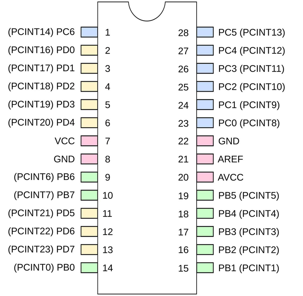
Figure 8-1. AVR pinouts—PCINT names
So if we want to trigger on PD2 and PD4, we can set the pin mask one of two ways. We can either use the pins’ PCINTxx aliases, or the normal PD2 type pin references. For instance:
PCMSK2 |= ( (1 << PCINT18) | (1 << PCINT18) );
and:
PCMSK2 |= ( (1 << PD2) | (1 << PD4) );
both do the same thing: configure the pin-change interrupt to trigger if either PD2 or PD4 changes state.
If you have an interrupt that is triggered by multiple pins, you’ll need to test which pin actually changed state in the ISR itself. For instance, continuing the preceding two-button example:
if (bit_is_clear(PIND, PD2)){
// Do one thing...
}
if (bit_is_clear(PIND, PD4)){
// Do another
}
Now you’ll be able to respond nearly instantly to input on any or all of the AVR’s pins.
PIN-CHANGE INTERRUPTS MADE EASY
Using pin-change interrupts allows your code to respond instantaneously to a voltage change on any or all(!) AVR pins. Just remember the three-tiered system for configuring pin-change interrupts and you’ll be all set:
1. Enable your specific interrupt in the control register: PCICR |= (1 << PCIEx)
2. Set which pins you’d like to react to in the appropriate pin-mask register: PCMSKx|= (1 << PCINTyy) or PCMSK0|= (1 << PB2)
3. Enable interrupts globally with sei() when you’re ready.
Now write the code that you’d like to run using the ISR(PCINTx_vect) macro:
1. If you’re triggering off of multiple pins in the same bank, you will want to test which pin just caused the interrupt in your ISR with something like bit_is_clear(BUTTON_IN, BUTTON).
2. Even if you’re triggering on only one pin in the bank, remember that pin-change interrupts trigger on any pin change. If you care whether the change is a press or release, you will need to test for that.
Capacitive Sensor
Capacitive sensors are pretty cool. I mean, who doesn’t like a button that can be pressed through a piece of paper or even just by waving your hand near a metal plate? Regular pushbuttons are old-tech, reliable, and despite their debouncing requirements, quite easy to use. When you want something that’s just a bit fancier, a little temperamental, and just a tad futuristic, you’ll want a capacitive touch sensor. Touching metal plates is what they do in the “future.”
The basic principle behind capacitive touch sensors is the same: timing how long it takes for a capacitor to charge or discharge. When nobody is nearby, the sensor plate itself will have some roughly fixed capacitance of its own, and it will take a given amount of time to charge and discharge at a given voltage. When you come along, your body capacitance couples with the circuit. The resulting capacitor—made up of you and the sensor—has more capacitance than the sensor’s capacitor alone, and so takes longer to charge and discharge. Measuring the change in charge time, allowing for environmental variation and more, lets you determine when the “button” is pressed.
Timing the capacitor’s discharge time directly involves detecting the difference between times that are on the order of two or more microseconds different from each other, and that’s a little bit unreliable and hard to do with great sensitivity. Instead if you fire off a pin-change interrupt service routine that recharges the capacitor and adds one to a count variable, and then time how many of these cycles you get in 50 milliseconds, you’ll get a number that ranges between 2,000 with your hand on the sensor plate, 8,000 with a thumb, 10,000 with a finger, 12,000 with your hand 1 cm above the plate, and 15,000 counts when you’re nowhere near the sensor.
CAPACITIVE SENSOR TIMING METHODS
All capacitive sensor applications work by measuring the time it takes to charge or discharge a baseline capacitor, and then comparing that with the extra time it takes to charge or discharge the same capacitor when the capacitance changes due to the proximity of a human. The approaches differ in how the timing of an individual charge/discharge cycle is done, and how these times are averaged together.
The most intuitive method is to directly time the capacitor discharging with nobody touching it, then with someone touching it, and compute the difference in time. If a human body adds around 20–30 pF of extra capacitance, and the capacitor is drained through a 100k ohm resistor as we do here, the time difference is one or two microseconds. With the AVR’s processor running at eight instructions per microsecond at best, we just don’t have much resolution with times that are that short.
Instead, we indirectly time how long it takes the capacitor to discharge by discharging it to a fixed level (where the digital pin reads a logic change), fully charging it back up, and then repeating. Because we’re always charging and discharging the capacitor, we can then count how many cycles take place in a fixed amount of time. This has the added advantage of averaging a bunch of cycles together—as many fit in our fixed time frame—so that if one cycle is a little too short due to some random fluctuation, and another cycle is too long, they cancel out.
In the end, the direct and indirect methods are very similar, and either is workable. I encourage you to make a direct-timing capacitive sensor if you’d like to experiment.
As demonstration code, a capacitive sensor lets me show you how interrupts let you do two things “at once.” We’ll use the plain-vanilla _delay_ms() function to implement the waiting time. Now normally, your code doesn’t do anything while a delay is running. But here we’ll be charging up the capacitor and keeping track of how many cycles we’ve seen in an interrupt that’s fired automatically every time the capacitor is discharged. So every time the ISR is called, the chip stops delaying, recharges the capacitor, increments a counter, and then goes back to the delay function where it left off. Cool, no? But first, we’ll need to build ourselves a sensor.
The Sensor
A capacitive sensor is basically just a capacitor. But unlike normal capacitors where the goal is to minimize the size and prevent it from interacting with electric fields in the environment, here you’ll be building your own capacitor as large as you’d like and trying to integrate your hand into the electric field.
Consequently, you can make a fairly low-tech capacitor. In fact, a very nice sensor for this project can be made by taking two pieces of aluminum foil with a sheet of paper between them. For starters, cut one piece of foil approximately 10 × 10 cm (3–4 inches on a side) to act as a ground plane. Clip an alligator clip to this foil. Put a sheet of paper on top of this, then a second smaller piece of aluminum foil. This piece of foil should be around half the size of the first in both dimensions—you want the ground plate to overlap the sensor plate at least where you’re going to be touching it. Attach the second alligator clip to the sensor foil. In my installation, I taped both foils to the piece of paper, using both the tape and paper to strengthen the foil. The two foils should be totally insulated from each other by the paper, and make sure that the alligator clips aren’t touching each other either. You can see how my completed sensor looks in Figure 8-2.
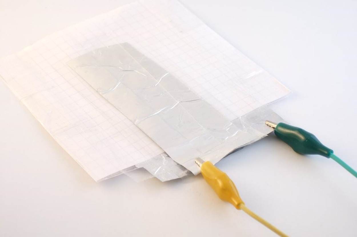
Figure 8-2. Aluminum foil capacitive sensor
Figure 8-3 shows you the resulting circuit diagram.
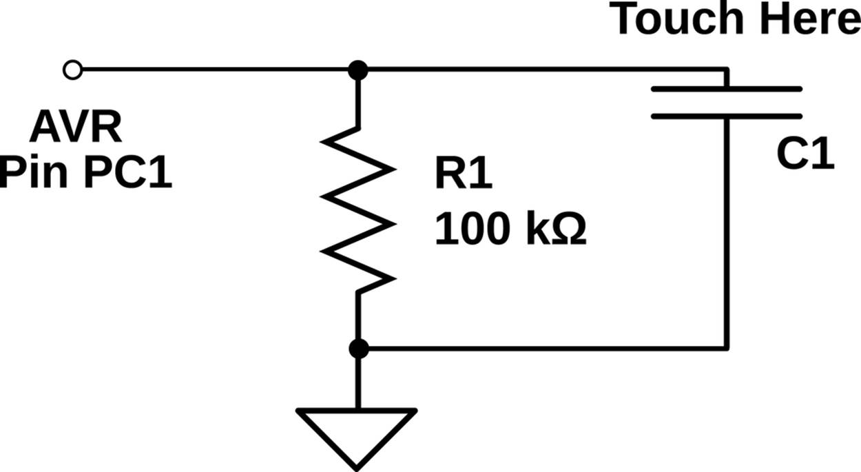
Figure 8-3. Capacitive sensor circuit
As you can see, the circuit is very simple. Connect a 100k ohm resistor from the AVR’s PC1 to ground. Now connect the ground-plate alligator clip to ground, and the sensor-plate alligator clip to the resistor and the AVR’s PC1. (See how the circuit diagram ends up looking just about like the two pieces of aluminum foil on your desk? This is no coincidence!) If you’ve already got an LED or two plugged in to PORTB, you’re done! The result on your breadboard should look something like Figure 8-4.
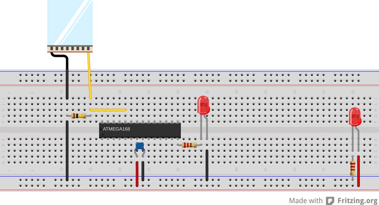
Figure 8-4. Capacitive sensor breadboard
The AVR will now charge up the capacitor and then switch to input mode. The large resistor will slowly discharge the capacitor back down to 0 V. And then you measure (indirectly) the time it takes for the capacitor to discharge and see if you’re touching the plate or not.
Once you’ve gotten it working the “right” way, feel free to experiment around with other capacitor geometries. Any conductive surface held insulated over a ground plane should work, in principle. By reading the number of counts per sensing period over the serial port, you’ll be able to figure out a suitable sensing time and threshold value for almost any capacitor. For instance, I dunked my alligator clip in a cup of tea that was sitting on top of grounded aluminum foil, and it could sense when I put my hand on the mug. You could also try taping the aluminum foil and paper sensor underneath a thin-seated chair to detect when a person sits down. You have a lot of room to experiment here.
The Code
OK, so down to business. To recap, we’ll be repeatedly charging up the sense capacitor and letting it discharge through the resistor, counting up the number of cycles. A delay function keeps track of the time. Once the delay is over, the number of charge-discharge cycles can be used to detect a nearby hand. Example 8-2 implements these ideas in code.
Example 8-2. capSense.c listing
/*
Capacitive touch sensor demo
*/
#include <avr/io.h>
#include <util/delay.h>
#include <avr/interrupt.h>
#include <avr/power.h>
#include "pinDefines.h"
#include "USART.h"
#define SENSE_TIME 50
#define THRESHOLD 12000
// ------- Global Variables ---------- //
volatile uint16_t chargeCycleCount;
// ------- Functions -------- //
void initPinChangeInterrupt(void) {
PCICR |= (1 << PCIE1); /* enable Pin-change interrupts 1 (bank C) */
PCMSK1 |= (1 << PC1); /* enable specific interrupt for our pin PC1 */
}
ISR(PCINT1_vect) {
chargeCycleCount++; /* count this change */
CAP_SENSOR_DDR |= (1 << CAP_SENSOR); /* output mode */
_delay_us(1); /* charging delay */
CAP_SENSOR_DDR &= ~(1 << CAP_SENSOR); /* set as input */
PCIFR |= (1 << PCIF1); /* clear the pin-change interrupt */
}
int main(void) {
// -------- Inits --------- //
clock_prescale_set(clock_div_1); /* full speed */
initUSART();
printString("==[ Cap Sensor ]==\r\n\r\n");
LED_DDR = 0xff;
MCUCR |= (1 << PUD); /* disable all pullups */
CAP_SENSOR_PORT |= (1 << CAP_SENSOR); /* we can leave output high */
initPinChangeInterrupt();
// ------ Event loop ------ //
while (1) {
chargeCycleCount = 0; /* reset counter */
CAP_SENSOR_DDR |= (1 << CAP_SENSOR); /* start with cap charged */
sei(); /* start up interrupts, counting */
_delay_ms(SENSE_TIME);
cli(); /* done */
if (chargeCycleCount < THRESHOLD) {
LED_PORT = 0xff;
}
else {
LED_PORT = 0;
}
printWord(chargeCycleCount); /* for fine tuning */
printString("\r\n");
} /* End event loop */
return (0); /* This line is never reached */
}
The pin-change interrupt initialization is the minimal setup—we set the pin-change interrupt for the bank of pins that we’d like to trigger and then the pin-mask for the particular pin we’re interested in. The only thing this initialization doesn’t do is enable the global interrupt vector. We’ll do that from within main().
The interrupt service routine does three things. First it increments our cycle variable. Then it changes the DDR to output and delays a tiny bit to charge up the capacitor. (The delay may or may not be necessary depending on your setup. Try it without.) Then, the DDRis set back to input for the pin, and the pin-change interrupt flag is cleared by writing PCIF1 into the pin-change interrupt flag register, PCIFR.
Resetting the pin-change interrupt flag is described in the datasheet, in the pin-change interrupts “Register Description” section if you’d like to read more. Why did we do this? Because, during the pin-change ISR, we change the voltage on the pin by charging up the capacitor, which sets the interrupt flag. If we didn’t reset the flag, program execution would jump right back to the pin-change ISR as soon as the ISR is done.
Moving down to the main() routine, we set the chip to run at maximum speed and call the initialization routines. (I go into more depth on setting the CPU speed in CPU Speed, so sit tight until then. I’ve been trying to explain everything in place, but this code just works so much better with the AVR in high-speed mode that I had to do it.)
Because the ISR will be swapping between charging the capacitor and passively reading its voltage, we can leave the PORT register high for charging, but we don’t want it to enable the internal pull-up resistor when we’re sensing the voltage. It turns out that we can disable all of the internal pull-up resistors with a single bit: setting MCUCR |= (1 << PUD);, the pull-up disable bit in the MCU control register.
The event loop then resets the charge cycle counter, initially charges up the capacitor, and then enables interrupts. As soon as the voltage on the capacitor drops back down, the ISR will be called, which will add one to the counter and then charge the capacitor back up. This cycle loops around until the delay is up and the code again disables interrupts. Now we can test how many cycles happened during the delay time and decide whether a press happened or not.
Global, Volatile Variables
There’s one more important detail in the capacitive sensor code that I brushed over in the preceding treatment, and that’s the use of global variables with our interrupt service routine. Have a look back at where the variable chargeCycleCount is defined, way up at the top of the file. Being defined outside of any function like this makes the variable global, meaning that any of the other functions defined in this file can access it without explicitly passing it as an argument to that function. This makes the variablechargeCycleCount available to both our main() routine and the ISR.
Remember back in The ISR() Is a Special Function where I said that ISRs were not entirely equivalent to functions? Here’s where the difference really matters. We need to increment a variable in the ISR and then use it to make a decision in the main() function. How can we do that without passing arguments and return values between the ISR and main()? The answer is to define a global variable that’s defined outside of both functions, and so its value isn’t contained within the scope of either. The ISR can add tochargeCycleCount and main() can read it.
But chargeCycleCount also must be marked volatile because the compiler needs to be warned that it can change without notice in any given context. In fact, this distinction is so important that not declaring the variable as volatile will break the code. I’ll explain why in a bit, but it’s a little arcane.
If your eyes glaze over while reading the next section, just remember to always define your global variables using the special volatile keyword for the AVR, otherwise the compiler will optimize them away and your ISR won’t work.
The volatile keyword
volatile warns the compiler that the declared variable can change at any time without warning, and that the compiler shouldn’t optimize it away no matter how static it seems.
For a glimpse into the mind of the optimizing compiler, imagine you write code with a segment like this:
int main(void){
char a;
a = 'H';
while(1){
transmitByte(a);
}
}
The compiler is going to notice that nothing in your main() function changes the value of the variable a, and the optimizer will get rid of it entirely. The optimizer will instead compile the equivalent of this code for you:
int main(void){
while(1){
transmitByte('H');
}
}
which does the same thing, but is much shorter and doesn’t involve allocating scarce memory for a variable that never varies. A win, right?
The optimizer is pretty good about finding shortcuts through our code, and if we write code that uses a variable that doesn’t change, the optimizer is going to replace it with a constant. This is where we run afoul of interrupts. Because the ISRs are never explicitly called from within the main() function, the optimizer doesn’t know that the ISR is changing a variable relevant for main(), and it replaces it with a constant value.
In the capacitive sensor code, it looks like the variable chargeCycleCount is set to zero and then it’s never changed with the main() routine. An optimizing compiler will notice this and replace chargeCycleCount with 0 everywhere within main(). If the cycle count is always 0, the code thinks that the sensor is always being pressed, even when it’s not, and the sensor routine won’t work.
To tell the compiler that we expect our global variables to change without warning, we mark it volatile. Now the compiler won’t make assumptions that it knows what the variable’s value is.
What about our the AVR’s special memory registers like PINB that change all the time due to external input? If you dig deep enough into the include files (into sfr_defs.h to be precise), you’ll find that the macros that define the hardware register variables, PORTB andPINB and so on, are already defined as volatile so that the compiler can’t just ignore them, even if nothing in code changes them explicitly.
Forgetting to mark global shared variables as volatile is probably pitfall #1 in advanced AVR programming. If your ISR seems not to be working, and you’re sure you’ve run sei(), double-check your volatiles.
Aside: volatile in for loops
Another place you’ll want to define a variable as volatile is when you’re using a loop to do nothing but delay. Because it’s doing nothing, the compiler will optimize it away. The compiler loves to help your code run faster!
So when you write something like:
uint8_t i;
/* I'd really like to delay here */
for (i = 0; i < 200; i++){
;
}
hoping to slow the program down for something like 200 CPU cycles, the compiler notices the empty for loop and optimizes it to:
uint8_t i;
/* Compiler: I found a shortcut! */
Instead, if you declare the variable i to be volatile, the compiler doesn’t know that it can’t be changed by external subroutines during any step in the for loop, so it executes them all just to be sure:
volatile uint8_t i;
for (i = 0; i < 200; i++){ ; }
works just fine as a 200-CPU-tick (plus a couple more for setting up the for loop) delay.
On the other hand, if you write:
uint8_t i;
for (i = 0; i < 200; i++){
_delay_ms(100);
}
it will work fine because the compiler thinks it needs to call that _delay_ms() function 200 times.
VOLATILE AND ISRS: THE BOTTOM LINE
If you share a global variable between a function (including main()) and an ISR, you must declare that variable as volatile.
If you don’t, the compiler will not realize that the variable can change within the scope of the function because it never sees the ISR being called directly, and it will likely substitute a constant for your variable. Your code will compile just fine, but your ISR won’t do anything and you’ll scratch your head for 10 minutes until you remember reading this warning. I hope.
Debugging the Circuit
If you haven’t already, flash the program in, connect the serial port to your computer, and run the Python serialScope.py program. (You may have to tweak the PORT definition to match your serial port.) Now touch the sensor and you’ll see the current cycle count. You’ll want to play around with the defined SENSE_TIME and THRESHOLD. If you aren’t getting at least 5,000 counts when you are not touching the sensor plate, try increasing the SENSE_TIME until you do. Now touch the plate a few times. You want to set theTHRESHOLD somewhere in between the untouched reading and what it reads when you put your finger on the plate.
Setting the THRESHOLD too close to the no-press value can make the circuit sensitive to small changes in the intrinsic capacitance of the circuit with weather or people walking by. On the other hand, if you set the THRESHOLD too low, you might need to press down with two fingers or more. You just have to explore a bit until you get it working like you’d like, but that’s half the fun.
Capacitive touch sensors are tricky beasts to troubleshoot. One reason is that the extra capacitance you’re trying to detect is around the same magnitude as what’s normally called “stray capacitance”; that is, the capacitance from having wires next to each other, or running your alligator clips too close to a grounded metal surface.
The other reason these sensors can be finicky is that the capacitance of the sensor itself depends on what you make it out of, what kind of environment it’s in, the humidity, and other factors. We’ve got a lot of parameters that are variable in this system: sensor geometry and capacitance, sampling time (controlled by the delay), and the count threshold to detect a touch.
So where to begin? If you’ve built the sensor as described, with a 100k ohm resistor, you should be already in the right ballpark. You can substitute a variable resistor or potentiometer in for the 100k resistor, and sweep the value around, which will vary the discharge rate. If you find that you have to use very long sampling times just to get a reasonable number of cycles counted, you might try changing the resistor value.
On the other hand, if you’re getting too many counts per period, you might even be running into overflow problems. Remember that a 16-bit counting variable can only get up to 65,535 before it loops back around to zero. Try running a shorter SENSE_TIME at first, and increase it until you get into a reasonable ballpark, especially if you see the sensor value decrease down to, and through, zero when you move your finger slowly onto the sensor.
Once you get the sensor working reliably, experiment with different materials and configurations. Plants? That’s been done. What’s the strangest capacitive sensor you can come up with?
All materials on the site are licensed Creative Commons Attribution-Sharealike 3.0 Unported CC BY-SA 3.0 & GNU Free Documentation License (GFDL)
If you are the copyright holder of any material contained on our site and intend to remove it, please contact our site administrator for approval.
© 2016-2026 All site design rights belong to S.Y.A.