Versatile Routing and Services with BGP: Understanding and Implementing BGP in SR-OS (2014)
Chapter 10. General Applicability
So far throughout this book it has been relatively easy to categorize the uses of BGP into chapter-length chunks. There are, however, a number of applications for BGP that I haven't discussed yet. This chapter contains information on those applications, together with some small sections containing information on other general topics on using BGP in SR-OS that frequently generate “How do I…” or “Why does the system do…” questions.
IPv6 PE Router (6PE)
6PE provides the ability to interconnect IPv6 islands over an IPv4 MPLS backbone using IPv6-enabled PE routers and is described in RFC 4798.
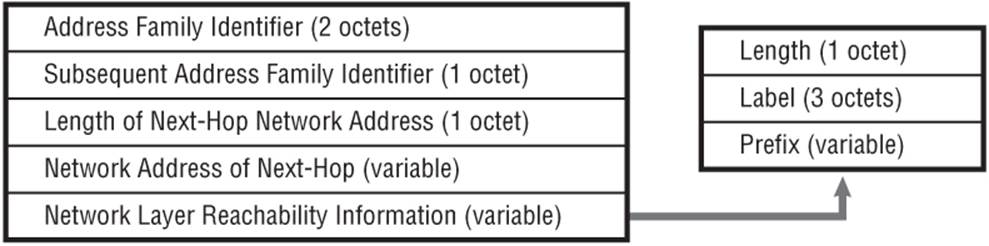
The PE routers operate as dual-stack with native IPv6 toward the IPv6 CE and IPv4 toward the core. IPv6 routes are exchanged between the PE and CE using an IGP or BGP, and advertised between PE routers using Multi-Protocol BGP AFI 2 (IPv6) SAFI 4 (NLRI with MPLS labels) to indicate the presence of a label. In SR-OS this label is always the Explicit-Null label (value 2). Like its IPv4 counterpart, the NLRI of the MP_REACH_NLRI attribute is encoded as a triple in the form <length, label, prefix>. Note that, unlike the extensions to BGP/MPLS IP-VPN for IPv6 described in Chapter 3 (referred to as 6VPE), 6PE does not provide any VRF-awareness.
Figure 10-1 MP_REACH_NLRI Labeled BGP Encoding
In the data plane, an IPv4 MPLS LSP must exist between ingress PE and egress PE. Any native IPv6 traffic received from the CE must be forwarded into the IPv4 LSP together with the Explicit-Null label advertised by that egress PE. So, a two-level label stack is used, consisting of the following:
· The Explicit Null label signalled with the IPv6 NLRI
· The transport label
In SR-OS, RSVP is not supported in conjunction with 6PE, so LDP must be used as the transport layer label distribution mechanism. The use of the Explicit-Null label means that the egress PE must always make a Layer-3 forwarding decision after the label stack has been popped.
The operation of 6PE is not considered IPv6-over-IPv4 because when tunnelling the IPv6 packets over the IPv4 MPLS backbone there is no IPv4 header imposed, but rather the ingress PE router performs label imposition directly onto the IPv6 packet.
To illustrate the use of 6PE I'll assume a simple scenario consisting of two PE routers providing IPv6 connectivity over an IPv4 MPLS backbone. PE1 has IPv6 interface 2001:DB8:1B01::/64, while PE3 has IPv6 interface 2001:DB8:1B03::/64. The MPLS control plane is LDP, and the PE routers are peered in IBGP with support for the IPv6 Address Family. An example of the service level configuration for support of 6PE is shown in Output 10-1 and simply exists of a native IPv6 interface toward the CE router.
Output 10-1: PE3 6PE Service Configuration
service
ies 101 customer 1 create
interface "PE-to-CE" create
ipv6
address 2001:DB8:1B03::1/64
exit
sap 1/1/3:101 create
exit
exit
no shutdown
exit
The BGP configuration at PE3 is shown in Output 10-2. In terms of incremental configuration requirements in support of 6PE, it consists of the command advertise-label ipv6 and a generic export policy to redistribute the directly connected IPv6 interface into BGP. Of course, if this Address Family is being added, it must be negotiated as a capability in an OPEN message and therefore triggers a Notification/OPEN exchange with the associated peers.
Output 10-2: PE3 6PE BGP Configuration
router
bgp
group "IBGP"
family ipv4 ipv6
peer-as 64496
neighbor 192.0.2.21
export "6PE"
advertise-label ipv6
exit
exit
no shutdown
exit
exit
Debug 10-1 shows the labeled IPv6 prefix 2001:DB8:1B03::/64 advertised by PE3 as received at PE1. The Next-Hop attribute is encoded as ::FFFF:C000:0217. When routes are advertised between PE routers, the Next-Hop attribute is encoded as an IPv4-mapped IPv6 address, prefixed with FFFF, with the IPv4 address carried in the low-order 32 bits. So, C000:0217 is the hex representation of PE3's system address 192.0.2.23. This decoded IPv4 Next-Hop address must be resolvable to an IPv4 LDP LSP. If it is not, the advertised prefix is held in RIB-IN and flagged as “invalid.”
Debug 10-1: IPv6 NLRI as Received at PE1
2 2013/06/17 10:10:55.18 UTC MINOR: DEBUG #2001 Base Peer 1: 192.0.2.23
"Peer 1: 192.0.2.23: UPDATE
Peer 1: 192.0.2.23 - Received BGP UPDATE:
Withdrawn Length = 0
Total Path Attr Length = 51
Flag: 0x90 Type: 14 Len: 33 Multiprotocol Reachable NLRI:
Address Family IPV6-Labeled
NextHop len 16 Global NextHop ::FFFF:C000:0217
2001:DB9:1B03::/64 Label 2
Flag: 0x40 Type: 1 Len: 1 Origin: 0
Flag: 0x40 Type: 2 Len: 0 AS Path:
Flag: 0x40 Type: 5 Len: 4 Local Preference: 100
"
As previously described, 6PE provides no VRF-awareness; therefore any advertised and valid prefixes are held in the IPv6 global routing table.
Output 10-3: IPv6 Route-Table
*A:PE1# show router route-table ipv6
==========================================================================
IPv6 Route Table (Router: Base)
==========================================================================
Dest Prefix[Flags] Type Proto Age Pref
Next Hop[Interface Name] Metric
--------------------------------------------------------------------------
2001:DB8:1B01::/64 Local Local 01h18m22s 0
PE-to-CE 0
2001:DB8:1B03::/64 Remote BGP 00h19m13s 170
192.0.2.23 (tunneled) 0
--------------------------------------------------------------------------
No. of Routes: 2
Flags: L = LFA nexthop available B = BGP backup route available
n = Number of times nexthop is repeated
==========================================================================
The specification in RFC 4798 outlines the use of 6PE in Inter-AS scenarios and makes comparisons with the Type A, B, and C described in Section 10 of RFC 4364. A Type A interconnect (EBGP redistribution of IPv6 routes from AS to neighboring AS) clearly will work because it essentially represents a PE-CE interface. However, the use of the Explicit-Null label imposes some restrictions on the use of Inter-AS Type B and C. The Explicit-Null label can be used only at the bottom of the label stack and indicates that the stack must be popped and forwarding based on the IPv6 header. For a Type B interconnect, there is a requirement to implement a swap of the service-level label, so Explicit-Null cannot be used across this form of interconnect. For a Type C interconnect, SR-OS cannot resolve a labeled IPv6 prefix to a labeled IPv4 prefix, so 6PE across this type of interconnect is also not possible.

The scenario where an SR-OS device is deployed as Route-Reflector for labeled IPv4 or IPv6 routes highlights an interesting problem. When the Route-Reflector receives a labeled prefix, it attempts to resolve the BGP Next-Hop (which is an IPv4 address for a labeled-IPv4 prefix or an IPv4-mapped IPv6 address for a 6PE prefix) to an LSP as part of its decision process. If the Route-Reflector is not running MPLS (which is a typical configuration for a control-plane-only Route-Reflector), any labeled prefixes in the RIB-IN are marked as “invalid.” In this case, the prefix is still reflected, but if there are a number of paths in the RIB-IN, only the first “invalid” path received is advertised. The workaround is to enable MPLS control plane on the Route-Reflector, in which case routes in the RIB-IN are considered “valid.”
The problem will be resolved by introducing the capability to instruct BGP to use the IP route table for resolving the Next-Hop of labeled IPv4 prefixes rather than the tunnel-table at a control-plane-only Route-Reflector.
Load-Balancing
Load-balancing provides the ability to maximize network capacity and aids fast reconvergence in a failure scenario because one or more backup paths are already installed in the FIB. To enable load-balancing, you must consider three key features: ECMP, IBGP-Multipath, and Multipath.
IBGP-Multipath
To understand the use of ibgp-multipath, consider the very simple topology in Figure 10-2. R1 and R2 are connected by two IP interfaces running IS-IS Level-2 and both have a metric of 100. Router R2 is advertising prefix 172.16.32.0/20 to router R1 in IBGP. (To be precise, both R1 and R2 are clients of Route-Reflectors, but this is not important to our discussion.)
Figure 10-2 IBGP-Multipath
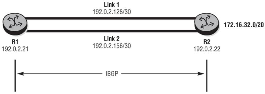
With the default configuration R1 sees the prefix 172.16.32.0/20 with Next-Hop 192.0.2.22 via Link 1. Although two IGP Next-Hops with equivalent metrics (100) are available, the router simply chooses one because ECMP is not enabled.
Output 10-4: R1 FIB Entry for 172.16.32.0/20
*A:R1# show router fib 1 172.16.32.0/20
==========================================================================
FIB Display
==========================================================================
Prefix Protocol
NextHop
--------------------------------------------------------------------------
172.16.32.0/20 BGP
192.0.2.130 Indirect (Link-1)
--------------------------------------------------------------------------
Total Entries : 1
--------------------------------------------------------------------------
==========================================================================
I'd like to load-balance traffic destined for the prefix 172.16.32.0/20 over both links between R1 and R2. First, I'll enable ECMP at the global router level. Although this can be up to 32 equal-cost paths, the topology dictates a requirement for only 2.
Output 10-5: ECMP Configuration
router
ecmp 2
Checking the FIB table in R1, the net effect of enabling ecmp 2 is that the system address of R2 is programmed for both Link 1 and Link 2, so IP traffic destined for this address will be load-balanced across both IP interfaces.
So far I haven't configured BGP to be able to utilize these equal-cost links, and this is the purpose of ibgp-multipath. When enabled, it effectively tells the system that if the BGP Next-Hop address resolves to multiple equal-cost IGP Next-Hops, both Next-Hops should be used.
Output 10-6: R2 System Address with ECMP=2
*A:R1# show router fib 1 192.0.2.22/32
==========================================================================
FIB Display
==========================================================================
Prefix Protocol
NextHop
--------------------------------------------------------------------------
192.0.2.22/32 ISIS
192.0.2.130 (Link-1)
192.0.2.158 (Link-2)
--------------------------------------------------------------------------
Total Entries : 1
--------------------------------------------------------------------------
==========================================================================
Output 10-7: IBGP-Multipath Configuration
router
bgp
ibgp-multipath
exit
If you now check the FIB table at R1 again you can see that the Next-Hop for prefix 172.16.32.0/20 is resolved indirectly to both Link 1 and Link 2.
The command ibgp-multipath is slightly misleading because it implies that it is effective only for IBGP. This is not the case, however. If R1 and R2 were peered in EBGP in Figure 10-2, the same steps would be required to load-balance traffic across both equal-cost paths.
For load-balancing within the context of a VPRN, the IBGP-Multipath feature is applicable only to BGP peering across PE-CE interfaces. That is, if the BGP Next-Hop resolves to two or more equal-cost IGP Next-Hops, traffic can be load-balanced across those interfaces. Load-balancing of traffic between PE routers across the core is a function of ECMP at the global router level.
Output 10-8: FIB output with ECMP and IBGP-Multipath Enabled
*A:R1# show router fib 1 172.16.32.0/20
==========================================================================
FIB Display
==========================================================================
Prefix Protocol
NextHop
--------------------------------------------------------------------------
172.16.32.0/20 BGP
192.0.2.130 Indirect (Link-1)
192.0.2.158 Indirect (Link-2)
--------------------------------------------------------------------------
Total Entries : 1
--------------------------------------------------------------------------
==========================================================================
Multipath
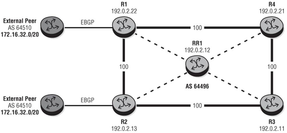
Next, consider the use of BGP multipath. To do that, use the topology shown in Figure 10-3. In this topology the routers R1 and R2 are learning prefix 172.16.32.0/20 from external peers and are reflecting the learned routes into IBGP toward R3 and R4 via a Route-Reflector RR1. ADD-PATH ensures that the prefix from R1 and the prefix from R2 are propagated by the Route-Reflector to other clients (R3, R4). The physical links are shown and all IGP (IS-IS) link metrics are set to 100. The objective is for R4 to load-balance traffic destined toward 172.16.32.0/20 over R1 and R2 toward both external peers using multipath.
Figure 10-3 Multipath Topology
At the outset, the router R4 receives the prefix 172.16.32.0/20 from R1 and R2 and prefers the route via R1 because of IGP cost to the BGP Next-Hop. Only this route is installed in the route-table and FIB, with the route from R2 held in RIB-IN as valid. (Output 10-9 doesn't show the modified attributes for the sake of brevity because they are effectively the same as the original attributes.)
Output 10-9: RIB-IN without Multipath
*A:R4# show router bgp routes 172.16.32.0/20 detail | match expression "Network|Nexthop|Flags|TieBreakReason"
Network : 172.16.32.0/20
Nexthop : 192.0.2.22
Res. Nexthop : 192.0.2.130
Flags : Used Valid Best IGP
Network : 172.16.32.0/20
Nexthop : 192.0.2.13
Res. Nexthop : 192.0.2.138
Flags : Valid IGP
TieBreakReason : NHCost
Output 10-10: FIB Entry without Multipath
*A:R4# show router fib 1 172.16.32.0/20
================================================================
FIB Display
================================================================
Prefix Protocol
NextHop
----------------------------------------------------------------
172.16.32.0/20 BGP
192.0.2.130 Indirect (to-R1)
----------------------------------------------------------------
Total Entries : 1
----------------------------------------------------------------
Multipath is enabled at the global router level and is enabled using the command multipath followed by a maximum number of paths. In the example, I'll keep the maximum number of paths to two.
Output 10-11: BGP Multipath Configuration
router
bgp
multipath 2
exit
The process of enabling multipath at R4 in the setup shown in Figure 10-3 has no immediate effect. There is only one preferred route via R1, and this is because by default BGP multipath must see the same IGP distance to the BGP Next-Hop for each path before more than one path can be used for load-balancing. In our setup, R4 has an IGP cost of 100 to R1 and an IGP cost of 200 to R2, so the route via R1 is preferred and the multipath is ineffective. To prove this, you can change the IGP metric of the link between R4 and R1 to a value of 200. That is, the cost from R4 to R2 is 200, and the cost from R4 to R1 is also now 200.
If you now take another look at the RIB-IN, you can see that the IGP distance to the BGP Next-Hop is not used in the decision process and lowest Originator ID is used instead. However, both routes are installed as “best.”
Checking the FIB entry for prefix 172.16.32.0/20, you also see that two entries are installed.
Output 10-12: Multipath with Equal Cost Routes
*A:R4# show router bgp routes 172.16.32.0/20 detail | match expression "Network|Nexthop|Flags|TieBreakReason"
Network : 172.16.32.0/20
Nexthop : 192.0.2.13
Res. Nexthop : 192.0.2.138
Flags : Used Valid Best IGP
Network : 172.16.32.0/20
Nexthop : 192.0.2.22
Res. Nexthop : 192.0.2.130
Flags : Used Valid Best IGP
TieBreakReason : OriginatorID
Output 10-13: FIB with Multipath and Equal Cost Routes
*A:R4# show router fib 1 172.16.32.0/20
================================================================
FIB Display
================================================================
Prefix Protocol
NextHop
----------------------------------------------------------------
172.16.32.0/20 BGP
192.0.2.138 Indirect (to-R3)
192.0.2.130 Indirect (to-R1)
----------------------------------------------------------------
Total Entries : 1
----------------------------------------------------------------
================================================================
If multipath is used on an EBGP peering session, it is very likely that the IGP metric to the BGP Next-Hop will be equal-cost (because they are probably directly connected). For IBGP peering, however, it is equally likely that the IGP metrics to the BGP Next-Hop are not equal-cost. The previous example of modifying IGP metrics is clearly not viable and would almost certainly create a new problem in the process of solving one; therefore, the option exists to modify the BGP path-selection algorithm to ignore the IGP metric using the command ignore-nh-metric. In this example it is configured at R4 under the global BGP context as shown in Output 10-14.
Output 10-14: ignore-nh-metric configuration
router
bgp
multipath 2
best-path-selection
ignore-nh-metric
exit
Once configured, two paths are installed as “best” even though they have different IGP metrics to the BGP Next-Hop. In addition, two entries are installed in the FIB as previously illustrated. Some caution should be exercised when using ignore-nh-metric, however. In the previous example, if you configured ignore-nh-metric on routers R4 and R3, there would be a partial forwarding loop between those two routers. That is, R4 would load-balance to R1 (directly connected) and R2 via R3, and R3 would load-balance to R2 (directly connected) and R1 via R4, but traffic may loop between R4 and R3. To avoid this situation, ignore-nh-metric should be used in conjunction with a tunnelling technique such as IP-VPN or IGP shortcuts.
Under some circumstances it may be desirable to run ibgp-multipath and multipath in parallel. This is perfectly acceptable. In this scenario the system implements a recursive load-balancing mechanism, first load-balancing traffic to each of the Next-Hops for the prefix (multipath function) and then load-balancing traffic over the equal-cost paths to each Next-Hop (ibgp-multipath function).
When multipath is configured within a VPRN BGP context, it applies only to prefixes learned from PE-CE BGP peers. Load-balancing to the same prefix learned from more than one distant PE is a function of ECMP at the VRF level.
When ignore-nh-metric is configured within a VPRN context, it applies to the BGP best-path selection algorithm of Multi-Protocol BGP routes that are imported into the VPRN. For Multi-Protocol BGP routes, configuring ignore-nh-metric means that the system not only ignores the IGP metric to the BGP Next-Hop, but also ignores the LSP type used to resolve that BGP Next-Hop, with no preference for RSVP or LDP LSPs.
EIBGP Multipath
EIBGP multipath is an extension of multipath that allows for load-balancing among paths that a router learns from both EBGP and IBGP. It is intended for use within a VPRN context, so from a PE perspective the use of EIBGP multipath dictates the ability to load-balance to the same prefix learned through IPv4 BGP from a direct next-hop (CE router) and VPN-IPv4 BGP from a remote next-hop resolved through an MPLS LSP.
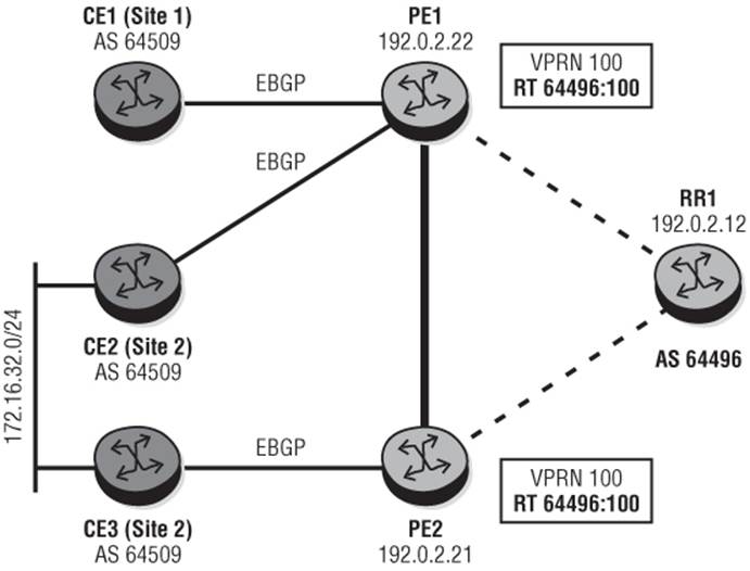
Figure 10-4 shows a use-case for EIBGP multipath. CE2 and CE3 represent a dual-homed site (Site 2) where CE2 is connected to PE1, and CE3 is connected to PE2. Both CE2 and CE3 are advertising the prefix 172.16.32.0/24 to their respective PEs in EBGP. CE1 is a single-homed site (Site 1) that is also connected to PE1. The objective would be for PE1 to load-balance traffic to 172.16.32.0/32 over the direct connection to CE2 and also via PE2's direct connection to CE3 to maximize the use of the capacity on the PE to CE connections.
Figure 10-4 EIBGP Multipath
PE1 learns the prefix 172.16.32.0/24 from CE2 and from PE2 (via CE3) and by default installs the route learned from CE2 as a result of Rule 6 of the BGP path selection algorithm: Prefer routes learned from an EBGP peer over routes learned from an IBGP peer.
Output 10-15: PE1 Preferred Path without EIBGP-Multipath
*A:PE-1# show router 100 route-table 172.16.32.0/20
==========================================================================
Route Table (Service: 100)
==========================================================================
Dest Prefix[Flags] Type Proto Age Pref
Next Hop[Interface Name] Metric
--------------------------------------------------------------------------
172.16.32.0/20 Remote BGP 00h42m40s 170
192.168.0.1 0
--------------------------------------------------------------------------
No. of Routes: 1
Flags: L = LFA nexthop available B = BGP backup route available
n = Number of times nexthop is repeated
==========================================================================
To enable load-balancing over EBGP and IBGP paths, you must enable ecmp >1 at the VPRN level if not already enabled, and configure eibgp-multipath within the VPRN BGP context.
Output 10-16: Enable EIBGP-Multipath at PE1
service
vprn 100
ecmp 2
autonomous-system 64496
route-distinguisher 64496:100
auto-bind ldp
vrf-target export target:200:100 import target:200:100
interface "CE2-Site2" create
address 192.168.0.2/30
sap 1/1/3:9.1 create
exit
exit
interface "CE1-Site1" create
address 192.168.0.18/30
sap 1/1/3:12.1 create
exit
exit
bgp
eibgp-loadbalance
group "EBGP"
neighbor 192.168.0.1
peer-as 64510
exit
neighbor 192.168.0.17
peer-as 64510
exit
exit
no shutdown
exit
After you've enabled eibgp-multipath, a check of the route-table for the VPRN at PE1 shows that both the EBGP learned route and the IBGP learned route are installed in the route-table as shown in Output 10-17. So, traffic from CE1 toward the prefix 172.16.32.0/32 will be load-balanced over both PE-CE connections to Site 2.
Output 10-17: PE1 Route-Table with EIBGP-Multipath Enabled
*A:PE-1# show router 100 route-table 172.16.32.0/24
==========================================================================
Route Table (Service: 100)
==========================================================================
Dest Prefix[Flags] Type Proto Age Pref
Next Hop[Interface Name] Metric
--------------------------------------------------------------------------
172.16.32.0/20 Remote BGP VPN 00h09m37s 170
192.168.0.21 (tunneled) 0
172.16.32.0/20 Remote BGP 00h09m37s 170
192.168.0.1 0
--------------------------------------------------------------------------
No. of Routes: 2
Flags: L = LFA nexthop available B = BGP backup route available
n = Number of times nexthop is repeated
==========================================================================
IGP Shortcuts
With conventional IP forwarding, every router in the forwarding path makes a routing decision, which in turn implies that every router must have adequate routing information available. In the case of Internet routing, it means that every router in the forwarding path must hold the Internet routing table. Although this is acceptable to some providers, others prefer that the core is “BGP-free.”
IGP shortcuts provide a mechanism for a forwarding router to resolve the BGP Next-Hop of a given prefix to an MPLS LSP. When the traffic has been encapsulated inside the LSP, any subsequent transit routers only perform a label-swap operation on any packets, and when the destination router pops the label stack it, can execute an IP routing decision before forwarding the traffic. Essentially, the IGP shortcut provides an MPLS tunnel between ingress router and egress router allowing transit routers to be BGP-free.
In Figure 10-5, Router R5 and R6 are IBGP clients of Route-Reflector RR1. R5 is advertising the prefix 172.31.100.0/24 with a Next-Hop of its system address 192.0.2.22. All physical adjacencies in the topology are configured to support both LDP and RSVP control planes, and router R6 has two equal-cost LDP LSPs to R5 (one via R4-R3 and one via R1-R2) and two explicit-routed, equal-cost RSVP LSPs to R5 (one via R4-R3 and one via R1-R2).
Figure 10-5 IGP Shortcuts
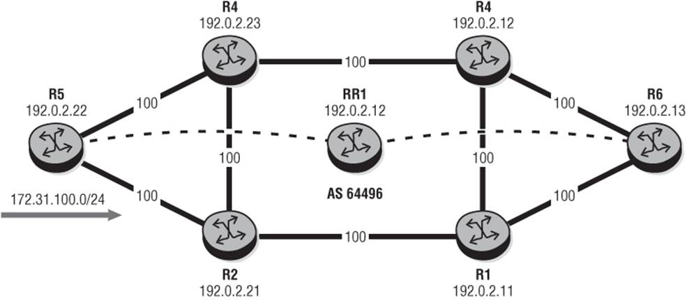
Output 10-18: R6 Tunnel Table
*A:R6# show router tunnel-table 192.0.2.22/32
==========================================================================
Tunnel Table (Router: Base)
==========================================================================
Destination Owner Encap TunnelId Pref Nexthop Metric
--------------------------------------------------------------------------
192.0.2.22/32 rsvp MPLS 2 7 192.0.2.150 300
192.0.2.22/32 rsvp MPLS 3 7 192.0.2.145 300
192.0.2.22/32 ldp MPLS - 9 192.0.2.145 300
192.0.2.22/32 ldp MPLS - 9 192.0.2.150 300
--------------------------------------------------------------------------
Flags: B = BGP backup route available
==========================================================================
Before enabling IGP shortcuts, you can verify that R6 is learning the prefix 172.31.100.0/24 with a Next-Hop of 192.0.2.22 (R5).
Enabling IGP shortcuts for BGP uses the igp-shortcut command and has the option to enable shortcuts using LDP, RSVP-TE, or simply MPLS. The latter prefers an RSVP-signalled LSP if the BGP Next-Hop can be resolved to one; if not it falls back to an LDP-signalled LSP. ibgp-multipathis also enabled in this setup because I'd like to load-share over the available LDP paths to R5.
Output 10-19: R6 RIB-IN for Prefix 172.31.100.0/24
*A:R6# show router bgp routes 172.31.100.0/24
==========================================================================
BGP Router ID:192.0.2.13 AS:64496 Local AS:64496
==========================================================================
Legend -
Status codes : u - used, s - suppressed, h - history, d - decayed,
* - valid
Origin codes : i - IGP, e - EGP, ? - incomplete, > - best, b - backup
==========================================================================
BGP IPv4 Routes
==========================================================================
Flag Network LocalPref MED
Nexthop Path-Id Label
As-Path
--------------------------------------------------------------------------
u*>i 172.31.100.0/24 100 None
192.0.2.22 21 -
64510
--------------------------------------------------------------------------
Routes : 1
==========================================================================
Output 10-20: IGP Shortcut Configuration
router
bgp
ibgp-multipath
igp-shortcut ldp
exit
With IGP shortcuts enabled for LDP, you can verify that the Next-Hop is resolved to two IGP Next-Hops; which in turn resolves to the two LDP LSPs shown in Output 10-18.
Output 10-21: BGP Next-Hop Resolution with LDP Shortcuts
*A:R6# show router bgp next-hop 192.0.2.22
==========================================================================
BGP Router ID:192.0.2.13 AS:64496 Local AS:64496
==========================================================================
==========================================================================
BGP Next Hop
==========================================================================
Next Hop Pref Owner
Resolving Prefix FibProg Metric
Resolved Next Hop Ref. Count
--------------------------------------------------------------------------
192.0.2.22 9 LDP
192.0.2.22/32 Y 300
192.0.2.145 1
192.0.2.22 9 LDP
192.0.2.22/32 Y 300
192.0.2.150 1
--------------------------------------------------------------------------
Next Hops : 1
==========================================================================
If you now modify the igp-shortcut configuration to make use of RSVP-TE shortcuts instead of LDP (that is, if you use the rsvp keyword instead of the ldp keyword) and recheck the BGP Next-Hop resolution, the BGP Next-Hop is no longer resolved to two LSPs (as in the LDP case), but just a single RSVP-TE LSP even though two equal-cost RSVP-TE LSPs exist. This is a known constraint when using RSVP-TE shortcuts.
Output 10-22: BGP Next-Hop Resolution with RSVP-TE Shortcuts
*A:R6# show router bgp next-hop 192.0.2.22
==========================================================================
BGP Router ID:192.0.2.13 AS:64496 Local AS:64496
==========================================================================
==========================================================================
BGP Next Hop
==========================================================================
Next Hop Pref Owner
Resolving Prefix FibProg Metric
Resolved Next Hop Ref. Count
--------------------------------------------------------------------------
192.0.2.22 7 RSVP
192.0.2.22/32 Y 300
192.0.2.150 1
--------------------------------------------------------------------------
Next Hops : 1
==========================================================================
The inability to load-balance traffic over multiple RSVP-TE LSPs to a single BGP Next-Hop is equally applicable to GRT and also IP-VPNs using either VPRN auto-bind rsvp-te or explicitly configured Spoke-SDPs. If RSVP-TE is required in conjunction with IBGP-Multipath load-balancing, the only solution is to use LDP over RSVP.
Split Horizon
To ensure a consistent view of routing information within an AS, a full-mesh of IBGP is provided (or Route-Reflectors are used). However, to avoid routing loops, a split-horizon rule is applied for IBGP in which prefixes learned from an IBGP peer are never advertised to another IBGP peer. This is the most commonly understood example of split horizon in BGP, but there is another interesting case that often causes confusion.
Consider the very simple topology in Figure 10-6, where Router R1 advertises prefix 172.16.0.0/20 to Router R2.
Figure 10-6 Split Horizon
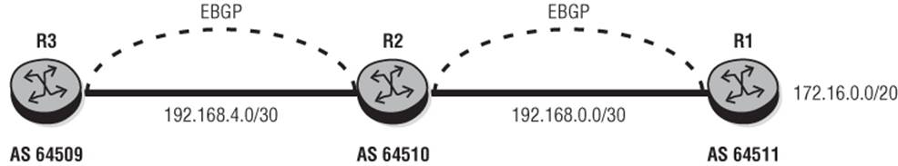
If you now look at the routes R2 has received from R1, you see the prefix 172.16.0.0/20 with AS_PATH 64511 and Next-Hop of 192.168.0.2 (R1). So far, so good.
Output 10-23: Received UPDATE from R1
*A:R2# show router bgp neighbor 192.168.0.2 received-routes
==========================================================================
BGP Router ID:10.46.46.46 AS:64510 Local AS:64510
==========================================================================
Legend -
Status codes : u - used, s - suppressed, h - history, d - decayed,
* - valid
Origin codes : i - IGP, e - EGP, ? - incomplete, > - best, b - backup
==========================================================================
BGP IPv4 Routes
==========================================================================
Flag Network LocalPref MED
Nexthop Path-Id VPNLabel
As-Path
--------------------------------------------------------------------------
u*>i 172.16.0.0/20 n/a 1
192.168.0.2 None -
64511
--------------------------------------------------------------------------
Routes : 1
However, if you look at the RIB-OUT entries for router R2, you see that it has correctly advertised the prefix to R3 (192.168.0.6), but R2 has also reflected the prefix back to R1 (192.168.0.2), adding its own AS in the AS_PATH path attribute and setting the Next-Hop to itself (192.168.0.1).
Output 10-24: R2 RIB-OUT
*A:R2# show router bgp routes 172.16.0.0/20 hunt | match post-lines 30 "RIB Out Entries"
RIB Out Entries
----------------------------------------------------------------
Network : 172.16.0.0/20
Nexthop : 192.168.0.1
Path Id : None
To : 192.168.0.2
Res. Nexthop : n/a
Local Pref. : n/a Interface Name : NotAvailable
Aggregator AS : None Aggregator : None
Atomic Aggr. : Not Atomic MED : None
Community : No Community Members
Cluster : No Cluster Members
Originator Id : None Peer Router Id : 192.168.0.2
Origin : IGP
AS-Path : 64510 64511
Network : 172.16.0.0/20
Nexthop : 192.168.0.5
Path Id : None
To : 192.168.0.6
Res. Nexthop : n/a
Local Pref. : n/a Interface Name : NotAvailable
Aggregator AS : None Aggregator : None
Atomic Aggr. : Not Atomic MED : None
Community : No Community Members
Cluster : No Cluster Members
Originator Id : None Peer Router Id : 192.168.0.6
Origin : IGP
AS-Path : 64510 64511
Router R1 drops this prefix because its own AS appears in the AS _PATH attribute. The rationale for this behavior is simply that by reflecting the route back to the sending peer and not subjecting it to a different (split-horizon) RIB-OUT policy, you can often improve the time to propagate the UPDATE, and also potentially conserve memory by not maintaining a different RIB-OUT for this peer. However, this behavior is sometimes undesirable, and in such an environment it is possible to disable this behavior using the split-horizon command.
Output 10-25: Enabling Split Horizon
bgp
group "EBGP-GROUP"
neighbor 192.168.0.2
peer-as 64511
split-horizon
exit
exit
no shutdown
exit
exit
With the split-horizon enabled, the prefix is again advertised from R1 to R2, and the RIB-OUT entry in R2 shown in Output 10-26 verifies that the split-horizon is in effect.
Output 10-26: R2 RIB-OUT with Split-Horizon Enabled
*A:R2# show router bgp routes 172.16.0.0/20 hunt | match post-lines 30 "RIB Out Entries"
RIB Out Entries
----------------------------------------------------------------
Network : 172.16.0.0/20
Nexthop : 192.168.0.5
Path Id : None
To : 192.168.0.6
Res. Nexthop : n/a
Local Pref. : n/a Interface Name : NotAvailable
Aggregator AS : None Aggregator : None
Atomic Aggr. : Not Atomic MED : None
Community : No Community Members
Cluster : No Cluster Members
Originator Id : None Peer Router Id : 192.168.0.6
Origin : IGP
AS-Path : 64510 64511
As illustrated in the example, enabling split-horizon solves the problem of reflecting routes back to the peer that advertised them. While the original intent of reflecting prefixes back to the advertising peer was to help optimize BGP performance, other improvements in UPDATE processing now make the different in performance negligible. As a result, enabling split-horizon should not cause any detrimental effect in performance.
Peer Groups
BGP peer groups are a set of peers that have a common administrative configuration. The general idea behind peer groups is that associating a number of peers together can dramatically improve RIB-OUT processing. Some BGP implementations achieve this by advertising the same UPDATE message across all peers of a peer group, which improves RIB-OUT UPDATEs/second but can suffer from head-of-line blocking when the advertising BGP speaker encounters a “slow peer.”
SR-OS allows for peer groups to be configured under the BGP context as shown in Output 10-27; however, this grouping is provided for operational ease because the grouping here does not necessarily dictate the forming of peer groups. Instead, the system internally organizes peers into groups known as “tribes.” A tribe can consist of up to 64 peers that are subject to common RIB-OUT processing, such as common export-policy, local-AS, peer-AS, AS-override, remove-private-AS, communities, and so on.
To fully utilize Multi-Core Processors and Symmetric Multi-Core Processing (SMP), peers are distributed across seven cores via I/O helper tasks that offload the process of writing to the TCP socket from the BGP process and other RIB-OUT work. Although peers are grouped into tribes, UPDATE messages are constructed for each peer.
Output 10-27: BGP Peer Group Configuration
bgp
group "EBGP"
family ipv4
neighbor 128.8.73.1
peer-as 64508
exit
neighbor 147.32.179.57
peer-as 64509
exit
exit
group "IBGP"
family ipv4 ipv6 vpn-ipv4 vpn-ipv6
export "ibgp-export"
peer-as 64496
neighbor 192.0.2.11
exit
neighbor 192.0.2.12
exit
exit
There are no show commands that provide visibility of tribe information, nor should it be necessary to view this information. However, note that the peer group information shown in Output 10-28 refers only to configured BGP peer groups. This output is taken from the router with the BGP configuration shown in Output 10-27. Here there are two configured peer groups, “EBGP” and “IBGP.” The group IBGP has two peers, which have the same local-AS, peer-AS, and export-policy and therefore belong to the same tribe. However, the group EBGP has two peers that have different peer-ASs, and as such each of them belongs to a different tribe. In essence, the total number of peer groups is two, but the total number of tribes is three.
Output 10-28: Peer Group Count
*A:R2# show router bgp summary | match Peer
Total Peer Groups : 2 Total Peers : 3
Total VPN Peer Groups : 3 Total VPN Peers : 3
BGP in Residential Broadband Networks
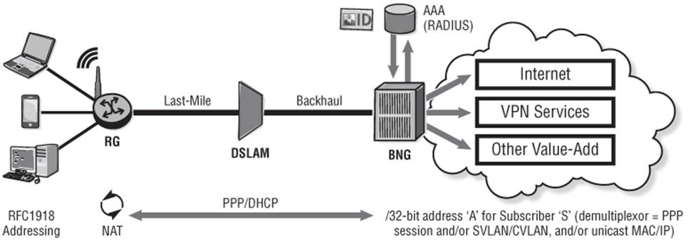
Access to the Internet using fixed broadband infrastructure has been an area of significant growth in the last decade or so. The growth is not just in its widespread accessibility and availability to residential users (to the point where a router in a home is considered just another “utility” like a refrigerator or freezer), but also last-mile access speeds have significantly improved because of the increased rollout of fiber (FTTC, FTTH) and the advancement of DSL line-bonding techniques. The result is that broadband infrastructure has become an appealing last-mile access mechanism for either primary or backup lines for enterprise businesses.
Broadband subscriber sessions (business and residential) are logically terminated on a Broadband Network Gateway (BNG) that provides the interface between the Layer-2 access network and Layer-3 services. For residential subscribers the Layer-3 service is typically Internet and/or local content caching, but for business users this also extends to IP-VPN services. The BNG interacts with the subscriber using PPP or DHCP, and because both protocols dictate a degree of state maintenance, they are typically used to implement “session awareness.” Session awareness is the ability to authenticate and identify a given subscriber, typically through interaction with RADIUS; apply policy to that subscriber; and maintain state for the period of the subscriber session. Policies that are applied to subscribers are typically dynamic and can implement a number of criteria including, for example, QoS, IP filtering, IP address management, and data accounting for billing purposes.
Typically a residential user is allocated a single IPv4 registered IP address using DHCP or PPP (IPCP), which is applied to the DSL (WAN) side of the home router or residential gateway (RG). Devices that are connected to the LAN side of that RG subsequently use private (RFC 1918) addressing and the RG implements Network Address Translation (NAT) to provide connectivity to the Internet for multiple hosts using a single, visible, registered IP address. The BNG holds an entry in its routing table for that 32-bit IPv4 address for that given subscriber and uses the PPP session and/or the SVLAN/CVLAN combination and/or the unicast MAC/IP as a demultiplexor for that subscriber.
Figure 10-7 Residential Subscriber Using NAT
To attract business services onto its broadband infrastructure, the challenge for the operator is to keep prices competitive while offering a level of differentiation over residential users. Much of this differentiation can be achieved with higher levels (or better granularity) of QoS, or lower levels of over-subscription for business users, but enterprises have other requirements that must be considered. One of those requirements is the ability to exchange routing information between sites of its enterprise network without the requirement for NAT. A method commonly used to achieve that is by using the RADIUS attribute “framed-route.” The “Framed-Route” attribute looks like a static-route and takes the format of <prefix/length> together with a Next-Hop1 (appended with optional metrics/tags) and is passed to the BNG from RADIUS during the subscriber activation. The RG continues to run PPP/DHCP to obtain an IP address for its DSL (WAN) side, and the BNG uses this WAN-side IP address as the Next-Hop for the “Framed-Route,” which is used on the LAN side of the RG. Once again, the BNG uses the PPP session and/or SVLAN/CVLAN and/or unicast MAC/IP as a demultiplexor for that subscriber.
Figure 10-8 Broadband Subscriber with Framed-Route
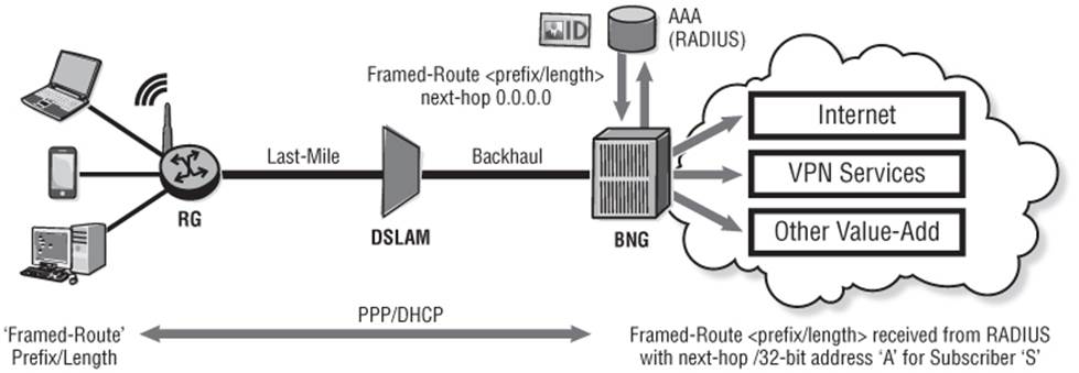
A key point with the use of Framed-Route is that there is no control plane interaction between the BNG and RG with regard to the prefix defined in the Framed-Route attribute. The RG LAN is statically configured with the corresponding <prefix/length>. The BNG installs the Framed-Route <prefix/length> into its routing table when the subscriber is activated and removes it from the route-table when the subscriber is deactivated. The point is that they act entirely independently.
Framed-Route is widely used for enterprise service delivery over broadband infrastructure, but it has drawbacks. For example, if the enterprise consumer wants to add an additional subnet on the RG LAN side, it is reliant on the Service Provider to make the change (add another Framed-Route attribute to its RADIUS infrastructure), which may be subject to some delay. Or, perhaps the RG has 20 or 30 subnets, which makes the use of Framed-Route cumbersome or even prohibitive. In this case you need the ability to exchange dynamic routing information between the RG and the BNG, and this is obviously where BGP becomes useful. However, this BGP session between the BNG and RG must be dynamic; it is required only when the subscriber is active and can be removed when the subscriber state is removed. That is the purpose of dynamic BGP policies.
Dynamic BGP policies provide the ability to automatically set up a peering session based on parameters from preconfigured BGP policies. When the subscriber is successfully authenticated, RADIUS returns one or more Vendor Specific Attributes (VSAs) that define the peering policy and parameters. Table 10.1 lists the available attributes that can be returned from RADIUS. The “Alc-BGP-Policy” attribute is the only mandatory attribute and must be returned when using dynamic BGP peering. Dynamic BGP peering attributes are ignored if the subscriber does not terminate within a VPRN. This makes sense given that the target for the feature is business/enterprise users.
Table 10.1 RADIUS VSAs for Dynamic BGP Peering
|
Attribute ID |
Attribute Name |
Description |
|
26-6527-55 |
Alc-BGP-Policy |
References the policy configured under subscriber-mgmt bgp-peering-policy <name> |
|
26-6527-56 |
Alc-BGP-Auth-Keychain |
References keychain parameters used to authenticate the BGP session using MD5 authentication for TCP |
|
26-6527-57 |
Alc-BGP-Auth-Key |
Indicates the authentication key to be used for MD5 authentication between the peers |
|
26-6527-58 |
Alc-BGP-Export-Policy |
References an export policy preconfigured using the SR-OS policy framework |
|
26-6527-59 |
Alc-BGP-Import-Policy |
References an import policy preconfigured using the SR-OS policy framework |
|
26-6527-60 |
Alc-BGP-PeerAS |
AS number of BGP neighbor |
As indicated in Table 10.1, the “Alc-BGP-Policy” refers to a BGP peering policy that is configured within the subscriber-mgmt context using the somewhat intuitive command bgp-peering-policy. Within the policy all the conventional BGP commands are available for use, but the policy does not permit any neighbor or group definition.
Output 10-29: Dynamic BGP Peering Policy Configuration
subscriber-mgmt
bgp-peering-policy "BGP-POLICY" create
as-override
authentication-key "bunEFexZcNPT5SsoHr158CBA/2xWi00N" hash2
disable-communities extended
peer-as 64510
prefix-limit 500
exit
exit
Within the associated VPRN context, there is a requirement to define an autonomous-system number, which will be used as the ASN in the OPEN exchange. Within the VPRN bgp context a group is defined with the creation-time keyword dynamic-peer. If necessary, additional BGP parameters can be applied here if they are not already defined in the BGP peering policy. The order for BGP parameter selection is as follows:
i. Use BGP peering parameters returned in Radius VSA attributes.
ii. If BGP peering parameters are not available from RADIUS, use those configured in the bgp-peering-policy.
iii. If BGP peering parameters are not configured in the bgp-peering-policy, use those configured for the dynamic-peer group.
iv. If BGP peering parameters are not configured in the dynamic-peer group, use the BGP peering parameters configured in the VPRN service BGP context.
v. If BGP peering parameters are not configured in the VPRN service BGP context, use the defaults.
Output 10-30: VPRN Configuration for Dynamic BGP Peering
service
vprn 1000
autonomous-system 64496
bgp
group "EBGP" dynamic-peer
exit
no shutdown
exit
no shutdown
So far, I've defined all the relevant parameters for peering, but what about the IP addresses that will be used to establish the TCP session? For dynamic BGP peering, SR-OS uses the IP address allocated to the subscriber during activation as the neighbor peering address. Using other addresses on the RG such as a loopback (for example, EBGP Multihop) is possible, but because dynamic BGP peering always uses the IP address allocated to the subscriber during activation, peering to a loopback requires that the peer is statically configured. In addition, it also requires that the RG sets the Next-Hop attribute on any UPDATE messages to the subscriber IP address.
From the perspective of the RG (or CPE), how the neighbor peering address is derived may change depending on the access method. For example, if PPP is used as an access method, during the IPCP exchange the BNG sends a CONF-ACK for a locally configured IP address (either an unnumbered interface address, or a subscriber-prefix address) that can be used as the neighbor peering address. If the access mechanism is DHCP, a default-gateway address is passed to the RG by the BNG in a DHCP OFFER. This can be used as a neighbor peering address or as a Next-Hop to a configured loopback interface. Either way, it is likely that the CPE must be configured with a neighbor address and potentially a static route to that neighbor address. That address, however, can be common to all RGs/CPEs that connect to a given BNG.
In this example, RADIUS is configured to pass only the mandatory attribute “Alc-BGP-Policy” with the preconfigured policy name “BGP-POLICY” to the BNG when the subscriber is successfully authenticated. Debug 10-2 shows the RADIUS Access Accept message for a PPP subscriber containing the BGP Policy VSA. Note also that the Framed-IP-Address attribute has a value of 255.255.255.254, which instructs the BNG to use a local pool for address allocation for this subscriber. This locally assigned IP address constitutes the neighbor peering address.
Debug 10-2: RADIUS Access-Accept with BGP Policy Attribute
26 2013/07/19 17:45:19.21 GMT MINOR: DEBUG #2001 Base RADIUS
"RADIUS: Receive
Access-Accept(2) id 74 len 235 from 192.0.2.250:1812
VSA [26] 19 Alcatel(6527)
SUBSC ID STR [11] 17 cpe-site1@acme.net
VSA [26] 14 Alcatel(6527)
SUBSC PROF STR [12] 12 ESM-SUB-PROF
VSA [26] 14 Alcatel(6527)
SLA PROF STR [13] 12 ESM-SLA-PROF
VSA [26] 6 Alcatel(6527)
MSAP SERVICE ID [31] 4 1000
VSA [26] 17 Alcatel(6527)
MSAP POLICY [32] 15 MSAP-POLICY
FRAMED PROTOCOL [7] 4 PPP(1)
SERVICE TYPE [6] 4 Framed(2)
FRAMED IP ADDRESS [8] 4 255.255.255.254
VSA [26] 16 Alcatel(6527)
BGP POLICY [55] 16 BGP-POLICY
"
In this subscriber activation, the BNG allocates an IP address of 192.168.0.30 to the subscriber from a local pool, and the subscriber setup is successful.
Configuration of SR-OS Enhanced Subscriber Management (ESM) is beyond the scope of this reference. However, note that anti-spoof nh-mac is a requirement when using dynamic BGP peering.
Output 10-31: BNG Subscriber Activation
*A:BNG1# show service active-subscribers
================================================================
Active Subscribers
================================================================
----------------------------------------------------------------
Subscriber cpe-site1@acme.net (ESM-SUB-PROF)
----------------------------------------------------------------
----------------------------------------------------------------
(1) SLA Profile Instance sap:[lag-10:60.1052] - sla:ESM-SLA-PROF
----------------------------------------------------------------
IP Address
MAC Address PPPoE-SID Origin
--------------------------------------------------------
192.168.0.30
00:00:65:02:01:02 1 IPCP
----------------------------------------------------------------
Number of active subscribers : 1
----------------------------------------------------------------
When the subscriber has been activated and the subscriber IP address is known, the BGP session can be set up, and UPDATE messages exchanged. When the subscriber state is removed, the BGP session is torn down and all resources associated with that session are released.
Operators delivering business services using dynamic BGP peering often use import and export BGP policies in much the same way as they are used on PE to CE peerings. (In fact, an export policy is required on the dynamic BGP peer to redistribute BGP-VPN routes to BGP routes.) As with other parameters, import/export policies can be derived from multiple places so a priority order is also defined for them as follows:
i. Use import/export policies returned in RADIUS VSA attributes and append any policies configured in the bgp-peering-policy.
ii. If import/export policies are not available from RADIUS and not configured in the bgp-peering-policy, use the policies configured in the dynamic-peer group.
iii. If import/export policies are not configured in the dynamic-peer group, use the policies configured in the VPRN service BGP context.
Output 10-32: BGP Summary Showing Dynamic BGP Peer
*A:BNG1# show router 1000 bgp summary
=========================================================================
BGP Router ID:192.0.2.12 AS:64496 Local AS:64496
=========================================================================
BGP Admin State : Up BGP Oper State : Up
Total Peer Groups : 1 Total Peers : 1
Total BGP Paths : 9 Total Path Memory : 1252
Total IPv4 Remote Rts : 1 Total IPv4 Rem. Active Rts : 1
Total McIPv4 Remote Rts: 0 Total McIPv4 Rem. Active Rts: 0
Total IPv6 Remote Rts : 0 Total IPv6 Rem. Active Rts : 0
Total IPv4 Backup Rts : 0 Total IPv6 Backup Rts : 0
Total Supressed Rts : 0 Total Hist. Rts : 0
Total Decay Rts : 0
=========================================================================
BGP Summary
=========================================================================
Neighbor
AS PktRcvd InQ Up/Down State|Rcv/Act/Sent (Addr Family)
PktSent OutQ
-------------------------------------------------------------------------
192.168.0.30
64510 15 0 00h03m49s 1/1/1 (IPv4)
13 0
-------------------------------------------------------------------------
QoS Policy Propagation Using BGP
QoS Policy Propagation using BGP (QPPB) is a feature that allows a route to be installed in the route-table with an associated Per-Hop-Behavior Group (internally referred to as a Forwarding Class, or FC) and priority so that packets matching the route receive the relevant QoS treatment.
Using QPPB, the QoS class that should be associated with a given prefix is typically signaled using a Community attribute, although any path characteristics of a BGP UPDATE message (such as AS_PATH) can be used if they can be referenced in policy, where the relevant FC and priority are configured as an “action” within each entry. Although the same behavior can be achieved using regular QoS policies, QPPB removes some of the operational overhead associated with manually updating IP “match” criteria associated with those policies.
An example application of QPPB is inter-AS coordination of QoS policies, where an operator in AS m may signal to a peer in AS n that traffic destined toward prefix P1 should receive Gold QoS treatment, but traffic destined toward prefix P2 should receive Bronze QoS treatment. Another application may be where an operator wants to provide differentiated QoS treatment to different traffic flows with known source/destination routes within its own administrative boundary.
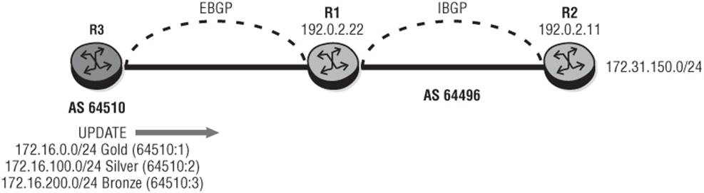
By way of demonstration, assume a simple and hypothetical scenario as shown in Figure 10-9 where routers R1 and R2 are in AS 64496 and R3 is an external peer in AS 64510. Router R2 is advertising prefix 172.31.150.0/24 while router R3 is advertising three prefixes and has an arrangement with AS 64496 that traffic sourced from those prefixes will receive differential QoS treatment within that AS. Prefix 172.16.0.0/24 is tagged with community 64510:1 indicating Gold QoS treatment. Prefix 172.16.100.0/24 is tagged with community 64510:2 indicating Silver QoS treatment, and prefix 172.16.200.0/24 is tagged with community 64510:3 indicating Bronze treatment.
Figure 10-9 QPPB Source-Lookup
First, I'll configure a simple QoS policy at R1 and apply it on the ingress from R3. This is simply for traffic differentiation and would have to be applied at all potential router hops if the Per-Hop-Behavior (PHB) were to be maintained throughout the Autonomous System. The objective is simply to show how the mechanism operates, so it's applied at ingress only and consists of three queues: queue 1 for Best Effort (BE), queue 2 for Assured Forwarding (AF), and queue 3 for Expedited Forwarding (EF). When traffic has been classified into the appropriate FC/priority at ingress using QPPB, that marking is retained throughout the system and subsequently used for FC to queue mapping on any egress interfaces.
Output 10-33: SAP-Ingress QoS Policy at R1 toward R3
qos
sap-ingress 10 create
queue 1 create
exit
queue 2 best-effort create
exit
queue 3 expedite create
exit
queue 11 multipoint create
exit
fc "af" create
queue 2
exit
fc "be" create
queue 1
exit
fc "ef" create
queue 3
exit
exit
exit
At the service level, an ingress QoS policy is applied. In addition, QPPB is enabled at the interface level using the qos-route-lookup command followed by the source or destination arguments, in this case source. This tells SR-OS to look up the source (or destination) IP address in the forwarding table associated with the routing context (GRT or VRF), and if the longest match prefix in the forwarding table has an associated FC and priority, to set the FC and priority based on that match. In the event the packet matches both QPPB qos-route-lookup criteria and some other statically configured criteria, the QPPB-derived classification overrides any statically configured criteria such as DSCP/IP precedence/802.1p.
Output 10-34: QPPB Configuration
service
ies 10 customer 1 create
interface "to-AS64510" create
address 192.168.0.2/30
sap 1/1/3:9.1 create
ingress
qos 10
exit
exit
qos-route-lookup source
exit
no shutdown
exit
Finally, the route policy is configured matching standard community values and setting the appropriate FC and priority. As previously indicated, any BGP path characteristic that can be referenced in policy can be used for QPPB classification. The route policy is then applied at import at R1 against the external peer R3.
Output 10-35: Example Route Policy for QPPB
router
bgp
group "EBGP"
neighbor 192.168.0.2
import "QPPB-AS64510"
peer-as 64510
exit
exit
exit
policy-options
begin
community "AS64510-Gold" members "64510:1"
community "AS64510-Bronze" members "64510:3"
community "AS64510-Silver" members "64510:2"
policy-statement "QPPB-AS64510"
entry 10
from
community "AS64510-Gold"
exit
action accept
fc ef priority high
exit
exit
entry 20
from
community "AS64510-Silver"
exit
action accept
fc af priority high
exit
exit
entry 30
from
community "AS64510-Bronze"
exit
action accept
fc be priority low
exit
exit
exit
commit
exit
Output 10-36 shows how the QPPB configuration applied at R1 can be verified for each prefix (the show router bgp routes <prefix> detail command can be used for the same purpose).
Output 10-36: Route-Table QoS Settings
*A:R1# show router route-table 172.16.0.0/16 longer qos
==========================================================================
Route Table (Router: Base)
==========================================================================
Dest Prefix[Flags] Type Proto Age Pref
Next Hop[Interface Name] Metric
QoS
--------------------------------------------------------------------------
172.16.0.0/24 Remote BGP 00h01m49s 170
192.168.0.1 0
ef, high
172.16.100.0/24 Remote BGP 00h01m49s 170
192.168.0.1 0
af, high
172.16.200.0/24 Remote BGP 00h01m49s 170
192.168.0.1 0
be, low
--------------------------------------------------------------------------
No. of Routes: 3
Flags: L = LFA nexthop available B = BGP backup route available
n = Number of times nexthop is repeated
==========================================================================
To verify that the QPPB classification is functioning correctly, you can run a ping from R3 to the destination prefix 172.31.200.1 connected to R2. The source address used for the ping is from the 172.16.100.0/24 range, which was previously advertised with the Gold community 64510:1 and classified as FC EF at R1. Output 10-38 shows the ingress QoS statistics at R1 after completion of the ping test, showing that all traffic was correctly mapped into queue 3.
QPPB is applicable to the IPv4 (AFI 1, SAFI 1), IPv6 (AFI 2, SAFI 1), VPN-IPv4 (AFI 1, SAFI 128), and VPN-IPv6 (AFI 2, SAFI 128) Address Families.
Output 10-37: Generate “Gold” Traffic from R5 to R2
*A:R5# ping router 9 172.31.200.1 source 172.16.0.1
PING 172.31.200.1 56 data bytes
64 bytes from 172.31.200.1: icmp_seq=1 ttl=62 time=4.20ms.
64 bytes from 172.31.200.1: icmp_seq=2 ttl=62 time=3.72ms.
64 bytes from 172.31.200.1: icmp_seq=3 ttl=62 time=4.06ms.
64 bytes from 172.31.200.1: icmp_seq=4 ttl=62 time=3.80ms.
64 bytes from 172.31.200.1: icmp_seq=5 ttl=62 time=12.3ms.
---- 172.31.200.1 PING Statistics ----
5 packets transmitted, 5 packets received, 0.00% packet loss
round-trip min = 3.72ms, avg = 5.62ms, max = 12.3ms, stddev = 3.35ms
Output 10-38: SAP-Ingress QoS Statistics with QPPB Classification at R1
*A:R1# show service id 10 sap 1/1/3:9.1 detail | match "Ingress Queue" post-lines 6
Ingress Queue 1 (Unicast) (Priority)
Off. HiPrio : 0 0
Off. LowPrio : 0 0
Dro. HiPrio : 0 0
Dro. LowPrio : 0 0
For. InProf : 0 0
For. OutProf : 0 0
Ingress Queue 2 (Unicast) (Priority)
Off. HiPrio : 0 0
Off. LowPrio : 0 0
Dro. HiPrio : 0 0
Dro. LowPrio : 0 0
For. InProf : 0 0
For. OutProf : 0 0
Ingress Queue 3 (Unicast) (Priority)
Off. HiPrio : 5 550
Off. LowPrio : 0 0
Dro. HiPrio : 0 0
Dro. LowPrio : 0 0
For. InProf : 5 550
For. OutProf : 0 0
Route Policy Framework
This section can't detail and illustrate all of the possibilities and capabilities made available in the SR-OS route policy framework. The aim is simply to provide an overview of how policy is configured and referenced while illustrating some fairly common use-cases when using policy with BGP.
The default BGP behavior without any policy applied is to accept all BGP routes and announce all BGP learned routes (subject to the best-path selection algorithm), but not to advertise any IGP, static, or local/connected routes. To advertise these types of routes, route policy must be used. This allows the user to control how routes are redistributed between protocols. In addition, it provides the ability to manipulate route characteristics such as metrics and path attributes.
Route policies are configured in a policy statement consisting of one or more policy entries. Each entry contains some match criteria followed by an action. Prefixes are parsed through the policy statement on an entry-by-entry basis in numerical order. If a match is found, the specific entry action is executed (accept or reject) and the prefix exits the policy evaluation. If no match is found in the first entry, the prefix is parsed through the next entry in the policy statement and continues to look for a match. If no match is found after all of the policy statement entries have been evaluated, a default action defines what action should be taken. The policy statement entries also allow multiple actions to be executed on the same prefix by nesting entries or even policy statements using an entry action of next-entry or next-policy. The policy statement also references objects outside the actual policy itself, including AS-path lists, prefix lists, and community lists. This section looks at some examples of these.
Whenever there is a requirement to add, modify, or delete policy and the user enters the config>router>policy-options context, it is necessary to enter the command begin to begin the policy creation, modification, or deletion. The user can thereafter make the necessary adds, moves, and changes, but they are entered in an off-line editing mode. That is, they are not applied until the command commit is entered. As a gentle reminder of this requirement, all policy configuration examples shown throughout this section include these commands.
Begin by looking at a relatively straightforward example of routing policy. The intention of the policy is to redistribute a directly connected prefix 172.31.100.0/24 into BGP while appending a standard community value of 64510:100. Output 10-39 shows the resulting policy. The community list “STD-COMM” defines the standard community value 64510:100, The prefix-list “LOCAL” defines the 172.31.100.0/24 with an exact suffix meaning that the prefix length that is evaluated must match the configured prefix length exactly; other options are a longer prefix length, or a length range either using the commands through (for example, 172.31.100.0/24 through 25) or prefix-length-range with a “from-to” range (for example, 172.31.100.0/24 prefix-length-range 32-32).
The policy-statement “BGP-EXPORT” consists of a single entry, entry 10. Within this entry the from context defines match criteria, and in this example it references the previously configured prefix-list “LOCAL.” This prefix is used as input to the policy only if the prefix exists in the route-table. The optional to context allows control over which protocols the prefix can be advertised into; in this case the protocol is protocol bgp. The action accept context then adds the previously configured community list STD-COMM.
Output 10-39: Basic Redistribution and Community Appending
router
policy-options
begin
community " STD-COMM" members "64510:100"
prefix-list "LOCAL"
prefix 172.31.100.0/24 exact
exit
policy-statement "BGP-EXPORT"
entry 10
from
prefix-list "LOCAL"
exit
to
protocol bgp
exit
action accept
community add "STD-COMM"
exit
exit
exit
commit
exit
The configured policy can be applied at BGP level, group level, or neighbor level, both within the base BGP instance or within a VPRN BGP instance. Output 10-40 shows an example of the previously configured policy being applied at the neighbor level. Applying policy to peers in this manner is relatively simple. To avoid repetition, this section provides no further configuration examples.
Output 10-40: Applying Policy to BGP Peers
bgp
group "EBGP"
neighbor 192.168.0.1
export "BGP-EXPORT"
exit
exit
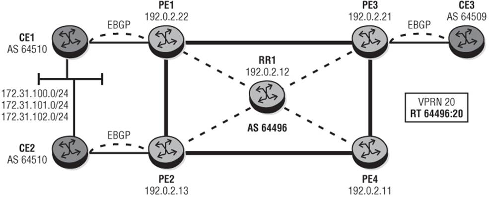
To provide some examples of commonly used route policies I'll use the topology depicted in Figure 10-10. PE1, PE2, and PE3 belong to AS 64496 and are delivering an IP-VPN service (VPRN 20) to CE1, CE2, and CE3. CE1 and CE2 represent a dual-homed site in AS 64510 while CE3 is in AS 64509. All CE routers peer in EBGP with their adjacent PE routers. Different Route distinguishers are used at PE1 and PE2 to ensure that common IPv4 prefixes advertised by CE1 and CE2 are propagated through the Route-Reflector as different VPN-IPv4 prefixes. A VPRN is used purely to demonstrate the use of policy at IPv4 and VPN-IPv4 level using both standard and extended community attributes. CE1 and CE2 are advertising prefixes 172.31.100.0/24, 172.31.101.0/24, and 172.31.102.0/24, which I'll use to manipulate path attributes through route policy at various points.
Figure 10-10 Test Topology for Route Policy
Basic Path Attribute Manipulation
To illustrate path attribute manipulation, I'll provide an example of the configuration requirements to modify the MED and LOCAL-PREF attributes at PE1 with the assumption that CE1 is advertising prefix 172.31.100.0/24 with the standard community attributes 64510:200, 64510:300, and 64510:400.
When PE1 receives the prefix 172.31.100.0/24 from CE1, there are two options regarding where policy can be applied:
· To the RIB-IN, which dictates the use of an import policy on the IPv4 BGP peering session toward CE1
· To the RIB-OUT, which dictates the use of an export policy on the VPN-IPv4 peering session toward the Route-Reflector RR1
I'll show the RIB-IN method first, and in this example I'll add the MED attribute. Output 10-41 shows an example of the route policy configuration at PE1 to identify prefixes with the standard communities added by CE1 and defined in the community list “CE1-STD-COMM.” Note that in its current format this community list represents a logical AND. That is, all members (standard communities) defined in the community list must be present before a match is made. I'll look at alternative ways of configuring this community list later in this section. The policy-statement again has a single entry (10) that looks for prefixes from protocol bgp and having the community values defined by the previously configured community list, and accepts them while setting an absolute metric (MED) value of 50. (Other options are to add, subtract, or derive MED from the IGP metric.)
Output 10-41: RIB-IN Policy at PE1
router
policy-options
begin
community "CE1-STD-COMM" members "64510:200" "64510:300" "64510:400"
policy-statement "PE1-IMPORT"
entry 10
from
protocol bgp
community "CE1-STD-COMM"
exit
action accept
metric set 50
exit
exit
exit
commit
exit
Output 10-42: MED Imposition at PE1
*A:PE1# show router 20 bgp routes 172.31.100.0/24 detail | match expression "Original Attributes|MED|Modified Attributes"
Original Attributes
Atomic Aggr. : Not Atomic MED : None
Modified Attributes
Atomic Aggr. : Not Atomic MED : 50
The route policy is applied as an import-policy at the BGP neighbor level within VPRN 20. If you check the RIB-IN for prefix 172.31.100.0/24 within VPRN 20, the original attribute contains no MED value (default), while the modified attributes (post RIB-IN policy) contain the MED value of 50 imposed by the route policy.
Using the same UPDATE from CE1, I'll remove the RIB-IN policy and show an example of setting policy on the RIB-OUT, where PE1 is advertising the prefix 172.31.100.0/24 in IBGP toward RR1 using the VPN-IPv4 Address Family (the actual VPN-IPv4 prefix is 64496:20:172.31.100.0/24). In this example, I'll impose the necessary extended community Route Target values to allow the prefix to be propagated throughout the sites of the VPN, and also manipulate the LOCAL-PREF attribute. In addition, assume that if either community 64510:200 or 64510:300 or 64510:400 is present in the UPDATE from CE1, the LOCAL-PREF should be set to 200, but any other prefixes should have the default LOCAL-PREF (100).
Output 10-43 shows the required configuration. In this example the community list “CE1-STD-COMM” uses regular expressions bounded by the ^ and $ symbols to indicate that the community AS number must be 64510, but the community value following the AS number can start with either 2 or 3 or 4, and then have two zeroes. Entry 10 then uses protocol bgp and community “CE1-STD-COMM” as match criteria in the from context, followed by to protocol bgp. The action accept provides the context to add the community list “VPRN20-RT-EXPORT” (in this case consisting of a single Route Target value of “target:64496:20”) and a local-preference value of 200. Entry 20 then takes any other prefixes learned through BGP and just appends the Route Target values defined in the community list “VPRN20-RT-EXPORT.” A default-action of reject ensures that nothing else is advertised into VPN-IPv4 for this VPRN service.
Output 10-43: RIB-OUT Policy at PE1
router
policy-options
begin
community "VPRN20-RT-EXPORT" members "
target:64496:20"
community "CE1-STD-COMM" members "^64510:2-400$"
policy-statement "VPRN20-RT-EXPORT"
entry 10
from
protocol bgp
community "CE1-STD-COMM"
exit
to
protocol bgp-vpn
exit
action accept
community add "VPRN20-RT-EXPORT"
local-preference 200
exit
exit
entry 20
from
protocol bgp
exit
to
protocol bgp-vpn
exit
action accept
community add "VPRN20-RT-EXPORT"
exit
exit
default-action reject
exit
commit
exit
Because I am appending Route Target extended community values to advertise into IBGP, the policy statement is applied at the VPRN level using the command vrf-export followed by the policy-statement name. It isn't shown in this example output because it isn't relevant to my prefix manipulation, but the vrf-export command is typically accompanied by a corresponding vrf-import statement and an associated import policy. The vrf-export command overrides any configured vrf-target export Route Target values, as will the vrf-import command override any configuredvrf-target import Route Target values.
Output 10-44: Applying Policy at VPRN Level
service
vprn 20 customer 1 create
vrf-export “VPRN20-RT-EXPORT”
exit
You can now check the prefix 172.31.100.0/24 as advertised by PE1 into VPN-IPv4 toward RR1 by checking the RIB-OUT as shown in Output 10-45. The standard community values imposed by CE1 are accompanied by an extended community Route Target value of 64496:20, while the LOCAL-PREF value has been set to 200.
Output 10-45: Verification of RIB-OUT Policy at PE1
*A:PE1# show router bgp routes vpn-ipv4 172.31.100.0/24 hunt | match
"RIB Out" post-lines 18
RIB Out Entries
--------------------------------------------------------------------------
Network : 172.31.100.0/24
Nexthop : 192.0.2.22
Route Dist. : 64496:21 VPN Label : 262140
Path Id : None
To : 192.0.2.12
Res. Nexthop : n/a
Local Pref. : 200 Interface Name : NotAvailable
Aggregator AS : None Aggregator : None
Atomic Aggr. : Not Atomic MED : None
AIGP Metric : None
Connector : None
Community : 64510:200 64510:300 64510:400 target:64496:20
Cluster : No Cluster Members
Originator Id : None Peer Router Id : 192.0.2.12
Origin : IGP
AS-Path : 64510
Neighbor-AS : 64510
Nested Policies (Next-Policy)
To illustrate the use of nested policies, I'll assume that both CE1 and CE2 are advertising prefixes 172.31.101.0/24 and 172.31.102.0/24. When CE1 advertises the prefix 172.31.101.0/24 it includes the standard attribute 64510:100, and similarly when CE2 advertises the prefix 172.31.102.0/24 it includes the standard attribute 64510:200. The routes are propagated into VPN-IPv4 by PE1 and PE2 without any path attribute manipulation, but both PE routers impose Route Target values 64496:20 and 64496:30.
The objective of this policy is that when the routes are received at PE3 they are imported into VPRN 20 if either Route Target 64496:20 or 64496:30 is present. In addition, a requirement is that PE3 prefers the prefix 172.31.101.0/24 (with standard community 64510:100) via PE1, and prefix 172.31.102.0/24 (with standard community 64510:200) via PE2. Lastly, for operational reasons this operator doesn't like to mix extended communities and standard communities within the same policy, so I'll use two policies; the first for Route Target import into the VPRN and the second for path attribute manipulation based on standard communities.
Output 10-46 shows the required configuration to deliver these requirements. In this example the community list CE1-STD-COMM matches the community value imposed by CE1 for prefix 172.31.101.0/24, while the community list CE2-STD-COMM matches the community value imposed by CE2 for prefix 172.31.102.0/24. The community list VPRN20-RT-IMPORT uses the expression keyword to implement a logical OR so that the Route Target values can be either target:64496:20 OR target:64496:30. Conventional regular expression characters cannot be used with extended community attributes when importing into a VPRN, but the use of the expression keyword together with the ability to specify a logical AND, OR, or NOT against Route Target values provides the ability to override the default community list logical AND behavior. This, in turn, can avoid a requirement for multiple policy statement entries.
The policy-statement VPRN20-RT-IMPORT is used for importing VPN-IPv4 prefixes. The from context references the previously configured community list VPRN-20-IMPORT. The action context indicates next-policy, and exactly which policy that should be is determined through the manner in which the policies are applied (for example, policy 1, policy 2). The policy-statement VPRN20-RT-IMPORT concludes with a default-action reject to ensure that no other Route Target values are imported into VPRN 20.
The policy-statement VPRN20-STD-COMM-IMPORT is the second policy. Entry 10 uses the from context to reference the community list CE1-STD-COMM and set the local-preference to 250 in the action accept context. Given the default local-preference value of 100, this ensures that PE1 is the preferred Next-Hop for the 172.31.101.0/24 prefix. Similarly, entry 20 uses the from context to reference the community list CE2-STD-COMM and set the local-preference to 250 in the action accept context. This ensures that PE2 is the preferred Next-Hop for the 172.31.102.0/24 prefix. The policy-statement concludes with default-action accept to allow prefixes that do not have any standard attributes attached. This is necessary in this scenario because the CE routers impose standard attributes only for those prefixes for which they are trying to attract traffic. That is, CE1 is advertising prefix 172.31.102.0/24 and CE2 is advertising prefix 172.31.101.0/24 without any standard attributes attached. If, for example, the link between PE1 and CE1 fails and PE1 withdraws the 172.31.101.0/24 prefix (carrying standard community 64510:100), PE2 must become the new Next-Hop for that same prefix (without any standard community value).
Output 10-46: VRF-Import Policy at PE3
router
policy-options
begin
community "CE1-STD-COMM" members "64510:100"
community "CE2-STD-COMM" members "64510:200"
community "VPRN20-RT-IMPORT" expression "target:64496:20 OR
target:64496:30"
policy-statement "VPRN20-RT-IMPORT"
entry 10
from
community "VPRN20-RT-IMPORT"
exit
action next-policy
exit
exit
default-action reject
exit
policy-statement "VPRN20-STD-COMM-IMPORT"
entry 10
from
community "CE1-STD-COMM"
exit
action accept
local-preference 250
exit
exit
entry 20
from
community "CE2-STD-COMM"
exit
action accept
local-preference 250
exit
exit
default-action accept
exit
exit
commit
exit
Again, because I am importing Route Target extended community values, the policy statements are applied at the VPRN level using the command vrf-import followed by the policy names in the order in which they should be evaluated. In this case, the policy statement VPRN20-RT-IMPORT is followed by the policy statement VPRN20-STD-COMM-IMPORT.
Output 10-47: VRF-Import Policy Application at PE3
service
vprn 20 customer 1 create
vrf-import "VPRN20-RT-IMPORT" "VPRN20-STD-COMM-IMPORT"
exit
Finally, you can check that the nested policies have implemented the required route imports and carried out the path attribute manipulation. Output 10-48 shows the original and modified attributes for the prefix 172.31.101.0/24 in the RIB-IN of PE3 summarized to the relevant lines of interest (Network, Next-Hop, Community, and Local Preference). The first two entries for network 172.31.101.0/24 have a Next-Hop of PE2 and have no standard community values set. As a result, the original and modified Local Preference values are the same at the default 100, but all the same the prefix is eligible for import into VPRN 20. The second two entries for network 172.31.101.0/24 are with a Next-Hop of PE1 and have the standard community 64510:100 in addition to the extended community Route Target attributes. As a result of the match on this standard community in the second policy statement, the original local preference value of 100 is modified to a value of 250, which makes it the preferred path.
Output 10-48: Nested Policy Verification at PE3
*A:PE3# show router bgp routes vpn-ipv4 172.31.101.0/24 detail | match expression "Network|Nexthop|Community|Local Pref."
Network : 172.31.101.0/24
Nexthop : 192.0.2.13
Res. Nexthop : n/a
Local Pref. : 100 Interface Name : to-PE4
Community : target:64496:20 target:64496:30
Network : 172.31.101.0/24
Nexthop : 192.0.2.13
Res. Nexthop : n/a
Local Pref. : 100 Interface Name : to-PE4
Community : target:64496:20 target:64496:30
Network : 172.31.101.0/24
Nexthop : 192.0.2.22
Res. Nexthop : n/a
Local Pref. : 100 Interface Name : to-PE1
Community : 64510:100 target:64496:20 target:64496:30
Network : 172.31.101.0/24
Nexthop : 192.0.2.22
Res. Nexthop : n/a
Local Pref. : 250 Interface Name : to-PE1
Community : 64510:100 target:64496:20 target:64496:30
A similar logic to the preceding output exists for the 172.31.102.0/24 prefix, and the desired behavior is seen in Output 10-49 showing PE3's route-table for VPRN20. Here the prefix 172.31.101.0/24 is preferred via 192.0.2.22 (PE1) while the prefix 172.31.102.0/24 is preferred via 192.0.2.13 (PE2). Because both CE routers advertise both prefixes but only attach a standard community value for the prefix for which they are attracting traffic, a backup path for both prefixes (with no standard community attached) remains in the RIB-IN in case of failure of the primary path.
Output 10-49: PE3 Route-Table for VPRN 20
*A:PE3# show router 20 route-table 172.31.101.0/22 longer
==========================================================================
Route Table (Service: 20)
==========================================================================
Dest Prefix[Flags] Type Proto Age Pref
Next Hop[Interface Name] Metric
--------------------------------------------------------------------------
172.31.101.0/24 Remote BGP VPN 00h53m16s 170
192.0.2.22 (tunneled) 0
172.31.102.0/24 Remote BGP VPN 00h53m16s 170
192.0.2.13 (tunneled) 0
--------------------------------------------------------------------------
No. of Routes: 3
Flags: L = LFA nexthop available B = BGP backup route available
n = Number of times nexthop is repeated
==========================================================================
Subroutines
Although multiple policies can be nested and evaluated in a serial manner as shown previously, this approach has the potential to make the process of configuration rather cumbersome when policies become complex. Instead of nesting policies in a serial manner, the use of subroutines allows the user to configure a policy statement entry that calls another policy (sub-policy) as part of its evaluation process. I'll show an example of policy using subroutines, and for completeness I'll include the entry action “next-entry,” which is used when the user wants to modify an attribute within an entry but does not want that prefix to exit the policy evaluation after the entry in question.
To demonstrate the use of subroutines and next-entry actions, assume that PE1 in AS 64496 belongs to a non-transit AS taking Internet transit from an ISP (formerly CE1) in AS 64510.2 The transit ISP is advertising a default route to AS 64496, and because of some configuration error it is also misannouncing the prefix 172.31.100.0/24 from the RFC 1918 private range toward AS 64496. For conciseness, the illustrated policies contain only a handful of entries and a production policy is likely to be significantly more extensive, but they serve to illustrate the function.
First, look at the policy that forms the subroutine at PE1's ingress from AS 64510. This is commonly referred to as a sub-policy but is configured in exactly the same way as any other policy. In this example, the subroutine implements a generic prefix rejection that can be referenced by various external policies toward other external peers. Output 10-50 shows the basic concept and consists of a policy-statement “SUB-ROUTINE” with two entries. Entry 10's from context references the prefix-list “RFC1918” containing all possible private address ranges, while entry 20's from context references as-path “AS_PATH>100” matching any UPDATE message containing more than 100 AS paths in the AS_PATH attribute.
If the purpose of this subroutine is to drop prefixes that match this criterion, why do both entries have an action of accept? When a policy calls a sub-policy for match criteria, the meaning of accept and reject in the sub-policy become true and false when returned to the calling policy. In other words, accept=true=match, and reject=false=no match. Therefore, if entry 10 of the sub-policy sees a prefix in the RFC1918 range, it returns a true/match indication, and it is then up to the calling policy to execute the appropriate action. The default-action is reject, meaning that all prefixes that do not match entry 10 and 20 return false/no match to the calling policy.
Output 10-50: Sub-Policy for Transit Peering Import at PE1
router
policy-options
begin
prefix-list "RFC1918"
prefix 10.0.0.0/8 longer
prefix 172.16.0.0/12 longer
prefix 192.168.0.0/16 longer
exit
as-path "AS_PATH>100" expression ".{100,}"
policy-statement "SUB-ROUTINE"
entry 10
from
prefix-list "RFC1918"
exit
action accept
exit
exit
entry 20
from
as-path "AS_PATH>100"
exit
action accept
exit
exit
default-action reject
exit
commit
exit
The calling policy that references the sub-policy in Output 10-50 and will be applied to the external peer is shown in Output 10-51. The policy statement “VPRN20-EBGP-IMPORT” has four entries. Entry 10 uses a subroutine and calls the sub-policy “SUB-ROUTINE” configured previously. Any prefix that is returned by the sub-policy with a “true” flag indicating a match is discarded because of the action reject command (in this case, any RFC 1918 prefixes and any prefixes with more than 100 entries in the AS_PATH attribute).
Entry 20 has no from context and therefore has no explicit match criteria. As a result, entry 20 is applicable to all prefixes being parsed through the policy and will remove all standard communities defined in the community list “ALL-INTERNAL-STD-COMM”. This community list uses regular expressions to list all standard communities in the range 64496:1000 to 9999 that the operator uses for AS-internal policy application. The action next-entry statement tells prefixes not to exit the policy, but to proceed to the next configured entry in the policy. Like entry 20, entry 30 has no fromcontext and is applicable to all prefixes being parsed through the policy. It references the community list “ALL-RT-EXT-COMM,” which uses regular expressions to match any Route Target extended community attributes these are subsequently removed. As shown previously, the action next-entry tells prefixes to continue through the policy.
Entry 40 uses a from context to match a standard community value 64510:100 defined by the community list “EXPENSIVE-TRANSIT-ISP.” Prefixes with this community are permitted by the action accept, but because this transit ISP is more expensive than AS 64496's other transit ISP's, the import policy appends the peering AS number in the AS_PATH two more times using the as-path-prepend command to influence internal routing decisions3 based on the AS_PATH length. The default-action reject means any other prefixes that do not have the standard attribute 64510:100 are rejected at PE1.
Output 10-51: Calling Policy for Transit Peering at PE1
router
policy-options
begin
community "ALL-INTERNAL-STD-COMM" members "^64496:1-9…$"
community "ALL-RT-EXT-COMM" members "target:^.*$&^.*$"
community "EXPENSIVE-TRANSIT-ISP" members "64510:100"
policy-statement "VPRN20-EBGP-IMPORT"
entry 10
from
policy "SUB-ROUTINE"
exit
action reject
exit
entry 20
action next-entry
community remove "ALL-INTERNAL-STD-COMM"
exit
exit
entry 30
action next-entry
community remove "ALL-RT-EXT-COMM"
exit
exit
entry 40
from
community "EXPENSIVE-TRANSIT-ISP"
exit
action accept
as-path-prepend 64510 3
exit
exit
default-action reject
exit
commit
exit
After applying the policy “VPRN20-EBGP-EXPORT” to the EBGP peering session between PE1 and AS 64510, you can look at the prefixes that PE1 is receiving from its peer. In Output 10-52, the transit peer is announcing the default-route, and also the misannounced private prefix 172.31.100.0/24. However, as shown in Output 10-53, only the default-route makes it to the route-table in VPRN 20 because the RFC 1918 prefix 172.31.100.0/24 is dropped by entry 10 of the import policy. Recall that this is the entry implementing subroutines and references a sub-policy to match these routes.
Output 10-52: PE1 Received Routes from AS 64510 Transit Peer
*A:PE1# show router 20 bgp neighbor 192.168.0.2 received-routes
==========================================================================
BGP Router ID:192.0.2.22 AS:64496 Local AS:64496
==========================================================================
Legend -
Status codes : u - used, s - suppressed, h - history, d - decayed,
* - valid
Origin codes : i - IGP, e - EGP, ? - incomplete, > - best, b - backup
==========================================================================
BGP IPv4 Routes
==========================================================================
Flag Network LocalPref MED
Nexthop Path-Id Label
As-Path
--------------------------------------------------------------------------
u*>i 0.0.0.0/0 n/a None
192.168.0.2 None -
64510
i 172.31.100.0/24 n/a None
192.168.0.2 None -
64510
--------------------------------------------------------------------------
Routes : 2
==========================================================================
Output 10-53: PE1's Route-Table for VPRN 20 after Import Policy
*A:PE1# show router 20 route-table protocol bgp
==========================================================================
Route Table (Service: 20)
==========================================================================
Dest Prefix[Flags] Type Proto Age Pref
Next Hop[Interface Name] Metric
--------------------------------------------------------------------------
0.0.0.0/0 Remote BGP 02h28m58s 170
192.168.0.2 0
--------------------------------------------------------------------------
No. of Routes: 1
Flags: L = LFA nexthop available B = BGP backup route available
n = Number of times nexthop is repeated
==========================================================================
Output 10-54: Subroutine Policy Verification at PE1
*A:PE1# show router 20 bgp routes 0.0.0.0/0 detail | match expression "Network|Nexthop|Community|AS-Path"
Network : 0.0.0.0/0
Nexthop : 192.168.0.2
Res. Nexthop : 192.168.0.2
Community : 64510:100 64496:1004
AS-Path : 64510
Network : 0.0.0.0/0
Nexthop : 192.168.0.2
Res. Nexthop : 192.168.0.2
Community : 64510:100
AS-Path : 64510 64510 64510
If you take a closer look at the prefix 0.0.0.0/0 received by the transit peer, you can verify that the policy has had the desired effect. In Output 10-54, the first entry for network 0.0.0.0./0 shows the original attributes as received from AS 64510. Of note is the fact that the UPDATE has the standard community 64510:100 but also contains one of the standard community values (64496:1004) that AS 64496 uses for internal policy application. Finally, the AS_PATH attribute contains only one entry, that of the transit ISP itself. The second entry for network 0.0.0.0/0 shows the modified attributes after policy has been applied to the RIB-IN. In this entry the community 64496:1004 has been stripped as a result of entry 20 of the import policy, which removes all standard community values in the range 64496:1000-9999, and the AS_PATH attribute now contains the AS number 64510 three times in total. In summary, the policy is functioning as expected.

Only a single level of policy nesting using subroutines is possible. For example, policy 1 can reference policy 2, but policy 2 cannot reference policy 3.
Notes
1. The next-hop 0.0.0.0 is a special case that essentially tells the BNG to use the IP address that it allocates from a local address pool as the next-hop for the framed-route.
2. Clearly a private AS number wouldn't be used by a Transit Internet Service Provider, but the use of a private AS number serves to illustrate the use of policy.
3. Prepending of AS paths is much more likely to be used when advertising prefixes externally because MED is non-transitive; however, the example serves to illustrate how it can be configured. When advertising internally into an AS, it is much more likely that LOCAL-PREFERENCE would be used and not as-path-prepend.
All materials on the site are licensed Creative Commons Attribution-Sharealike 3.0 Unported CC BY-SA 3.0 & GNU Free Documentation License (GFDL)
If you are the copyright holder of any material contained on our site and intend to remove it, please contact our site administrator for approval.
© 2016-2026 All site design rights belong to S.Y.A.