Versatile Routing and Services with BGP: Understanding and Implementing BGP in SR-OS (2014)
Chapter 11. Looking Ahead
Given that BGP is so flexible and extensible, it's no surprise that it continues to evolve to encompass more NLRI and extend its applicability. This chapter discusses a few of the more significant emerging uses of BGP. It provides an overview of these technologies and how they might be used. It is not a product roadmap.
Ethernet VPN (EVPN)
A BGP MPLS Based Ethernet VPN (EVPN) (draft-ietf-l2vpn-evpn) provides virtual Layer-2 bridged connectivity between a set of CE routers. PE routers providing this service are interconnected using MPLS LSPs or IP tunneling techniques such as GRE (in this context sometimes referred to as Network Virtualization GRE or NVGRE) in exactly the same way that is currently used to provide Layer-2 or Layer-3 VPN services today.
In a conventional bridged service (VPLS), MAC learning is done in the data plane, but for EVPN, MAC learning is done in the control plane. PEs supporting the EVPN advertise MAC addresses learned from connected CEs together with an MPLS label using Multi-Protocol BGP. Control-plane learning offers significant benefits over data-plane learning, such as reducing the requirement to flood and helping to improve reconvergence times for certain failure scenarios. One other major benefit of control-plane learning is that it enables flow-based load-balancing of traffic to CEs that are dual-homed. Today dual-homed sites must work in active/standby mode using methods such as BGP Multi-Homing, STP, or Multi-Chassis LAG to provide a loop-free topology, but EVPN allows active-active (known as All-Active) multi-homing using control-plane learning.
As you would expect, new technology means new terminology and new acronyms:
|
EVI |
An EVI is an EVPN instance that spans all of the PE routers participating in the VPN. Each EVI is associated with a Route-Distinguisher and one or more Route Targets, and the semantics and use of these are exactly the same as with BGP-MPLS IP-VPNs. MAC addresses are advertised in much the same way that PE routers supporting BGP-MPLS IP-VPN advertise IP reachability. |
|
MAC VRF |
A virtual routing and forwarding table for MAC addresses on a PE for a given EVI |
|
ESI |
If a CE is multi-homed to two or more PEs, the set of Ethernet links that attaches the CE to the PEs is known as an Ethernet segment, identified by an Ethernet Segment Identifier (ESI). |
|
Ethernet Tags |
An Ethernet Tag identifies a broadcast domain within an EVI, and each EVI can contain one or more broadcast domains. The Ethernet tag is encoded in the EVPN NLRI. When a PE receives an EVPN NLRI containing an Ethernet TAG, it has to perform a mapping to the attached CE VLAN Identifiers (CE-VIDs). The function of this mapping depends on the type of service interface, which can be VLAN-based, VLAN bundle-based, or port-based. VLAN-based service interfaces have a 1:1 mapping between the CE-VID and the EVI with a single bridge domain per PE for the EVI. VLAN-bundle based service interfaces have a N:1 mapping between the CE-VID and the EVI but again a single bridge domain per PE for the EVI (different CEs connected to different PE ports use the same CE-VIDs for the same EVI). Port-based services are essentially the same as VLAN-bundle services with the exception that all VLANs on the port are part of the same EVPN. A variation of the VLAN-bundle and port-based service interfaces makes them “VLAN aware,” permitting an N:1 mapping between the CE-VID and EVI, but with multiple bridge domains per PE per EVI. The Ethernet tag is present in the EVPN NLRI only when VLAN-aware service interface types are used. |
EVPN control plane is achieved using Multi-Protocol BGP using AFI 25 (L2VPN) SAFI 70 (EVPN). The NLRI is encoded as shown in Figure 11-1. It has the same format as the MVPN NLRI discussed in Chapter 7, although the Route Types differ to accommodate the requirements of the relevant technology. Table 11.1 lists the five Route Types that have been defined at present. The following sections discuss each of these Route Types.
Figure 11-1 EVPN NLRI
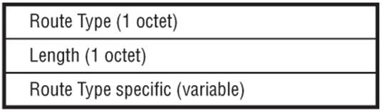
Table 11.1 EVPN NLRI Route Types
|
Value |
Route Type |
|
1 |
Ethernet Auto-Discovery (A-D) Route |
|
2 |
MAC Advertisement Route |
|
3 |
Inclusive Multicast Route |
|
4 |
Ethernet Segment Route |
|
5 |
IP Prefix Route |
Ethernet Auto-Discovery Route
The Ethernet A-D Route is advertised per ESI along with a new ESI Label Extended Community attribute to assist fast convergence, split-horizon filtering, and aliasing.
To assist fast convergence, upon failure of a given Ethernet segment, a PE router sends a withdraw for this ESI, which triggers all other PEs to update/flush their MAC tables for the associated MAC addresses. This helps to speed up convergence because advertising a single UPDATE for the ESI is significantly better than constructing one or a number of withdraws for all MAC addresses associated with that segment.
The split horizon rules widely used in VPLS are inherited for EVPN. When a PE router receives a broadcast, multicast, or unknown unicast frame from an attached CE, it sends it to all other attached CEs and also to all other PEs in the EVI. However, when a PE router receives an unknown unicast frame from another PE, it must forward it to attached CEs only if it is the DF for the egress ESI. It must never forward the frame to another PE.
However, All-Active multi-homing presents an additional challenge. Consider a CE that is multi-homed to two PEs on an Ethernet segment operating in All-Active mode. If the CE sends a broadcast packet to the non-DF PE, that PE sends the frame to all other PEs in the EVI including the DF for the Ethernet segment. The DF must drop that frame and not forward it back to the CE, and to achieve this behavior the ESI Label Extended Community attribute contains a label value (referred to as the ESI Label) that is distributed to all PEs when operating in All-Active multi-homing mode. Whenever a broadcast, unknown unicast, or multicast packet is forwarded on to the EVI from a non-DF PE, it is encapsulated with this ESI Label to identify the Ethernet segment of origin. When it reaches the DF PE, it uses the ESI Label to determine whether or not this frame can be forwarded on to the segment.
The Ethernet A-D route is also used for aliasing an ESI within a given EVI. Aliasing is a PE's capability to signal reachability for an ESI even when it has not learned any MAC addresses locally on that ESI. Consider the case where a CE is multi-homed to multiple PE nodes using a LAG with All-Active redundancy. It is quite conceivable (because of the hash routine on the CE) that only a single PE learns the MAC addresses of the multi-homed site; for example, if data-plane learning is implemented on the attachment circuit(s). This leads to a situation where remote PEs receive MAC advertisement routes only from a single PE of the PEs forming the multi-homed site and are therefore unable to effectively load-balance traffic destined toward the multi-homed site across all of the PEs supporting that site.
Using aliasing, PEs locally attached to an Ethernet segment signal the ESI in an Ethernet A-D route per EVI even when no MAC addresses have been learned. Remote PEs that receive MAC advertisement routes thereafter should consider the advertised MAC addresses as reachable through all PEs that have advertised both of the following:
· An Ethernet A-D route per EVI with the same ESI
· An Ethernet A-D route per ESI with the same ESI and with the Active/Standby bit set to 0 in the ESI Label Extended Community (see the sub-section on Multi-Homing Mode)
MAC Advertisement Route
The MAC Advertisement Route facilitates control-plane MAC learning, which can be local or remote. Local learning is learning of MAC addresses from directly connected CE routers using conventional data-plane learning, DHCP, or ARP. Remote learning is learning of MAC addresses that are behind CEs connected to other PEs. It is achieved by PEs advertising the MAC addresses it learns locally into a MAC Advertisement Route.
The MAC Advertisement Route contains (among other things) the ESI, Ethernet Tag ID, MAC, and MPLS label. It optionally can carry an IP address associated with the advertised MAC address. This provides the ability to create an IP-to-MAC binding, which can be beneficial in minimizing ARP or Neighbor Discovery procedures through use of proxy ARP. That is, if a PE receives an ARP request for a IP address for which it has a MAC binding, it can locally respond to that ARP request rather than propagate it through the EVI.
The ability to dynamically associate IP and MACs can be useful in Data Center environments. The Network Virtual Overlay over Layer 3 (NVO3) working group in the IETF has defined a framework for constructing overlay networks that operate on top of an IP-based underlay network. Anoverlay network is a virtual network in which the separation of tenants is not made visible to the underlying physical infrastructure. One overlay approach that is seeing some fairly widespread implementation is the Virtual Extensible Local Area Network (VXLAN), which encapsulates Ethernet frames in UDP/IP. The Ethernet frames are invisible to the underlay network, which is responsible purely for forwarding at the IP layer. These VXLAN tunnels are extended between Virtual Machines (VMs) and provide traffic separation between tenants, except through a carefully controlled interface such as a firewall. The VXLAN tunnels also allow for address space isolation, so that address space can be reused between tenants. A MAC Advertisement Route provides the ability to learn Virtual Machine (VM) MACs and associated VXLAN Tunnel End Points (VTEPs) and automatically create VXLAN tunnel bindings for intra-DC traffic, or for inter-DC traffic using a VPLS or VPRN at the DC gateway.
The process of control-plane learning has many benefits as previously outlined, but what if a host moves from one Ethernet segment to another segment? This scenario is fairly common in Data Center environments. If a host simply moves segments, the PE to which it is newly attached propagates a MAC Advertisement route when its MAC has been locally learned, but the PE to which it was previously attached very likely still has the same MAC address locally cached. This MAC Advertisement Route would still be active, which results in two active MAC advertisement routes (one of which is a blackhole). This scenario is called MAC mobility (or MAC move). To resolve this situation, the old MAC Advertisement must be withdrawn so that only one MAC Advertisement route is active. To achieve this, a MAC Mobility Extended Community attribute is introduced. When a PE router learns a local MAC address for which it had previously received a MAC Advertisement Route with a different ESI, it advertises the MAC address in a MAC Advertisement Route with a MAC Mobility Extended Community attribute. This serves as a trigger for other PEs to withdraw their advertisements for the same MAC, thus permitting mobility while avoiding blackholes.
Inclusive Multicast Ethernet Tag Route
When forwarding broadcast, unknown unicast, or multicast traffic, PEs in an EVI may use ingress replication, but to optimize the flooding procedure, options exist to use P2MP or MP2MP LSPs to distribute the replication function. To do this, each PE must advertise an Inclusive Multicast Ethernet Tag Route, which carries a PMSI tunnel attribute to identify the type of P-tunnel. This effectively uses the same procedure as BGP MVPN, discussed in Chapter 7.
Ethernet Segment Route
Ethernet Segment Route (Route Type 4) is used for automatic discovery of the PEs supporting the same ESI, and for Designated Forwarder (DF) election. The route is accompanied by an ES-Import Route Target Extended Community Attribute (different from a Route Target value) so that the route is imported only by PEs that are muti-homed to the same segment.
When multi-homing is used, whether it's All-Active or Single-Active, a single PE that connects to the ESI for a given EVI is nominated as Designated Forwarder (DF). The DF is responsible for flooding broadcast, unknown unicast, and multicast traffic onto a given ESI toward the CE, whereas the non-DF should discard these packets. To provide for All-Active load-balancing, both DF and non-DF can forward frames with known MAC destinations.
IP Prefix Advertisement Route
The optional IP Prefix Advertisement Route facilitates inter-subnet connectivity where EVPN is used as the control plane for a Network Virtualization Overlay (NVO3) solution within a Data Center environment. In this environment, Virtual Machines (VMs) can connect to the EVPN and generate traffic to/from their own IP and MAC address; or other Virtual Appliances (VAs), such as firewalls, load-balancers, or NAT devices, can forward traffic to/from IP addresses of different end devices sitting behind them with the same MAC address. These VMs or VAs do not run dynamic routing protocols, but instead rely on the Network Virtualization Edge (NVE) to advertise connected subnets on their behalf using the EVPN control plane. In addition, these VMs and VAs can be moved between or within the same or different Data Centers by Cloud Management Systems (CMS), so a level of mobility must be supported.
If the intent is that the NVEs advertise IP addresses together with a Next-Hop address, this sounds like a problem that has already been solved. Why not just use the BGP/MPLS IP-VPN (RFC 4364) control plane? There are multiple reasons why this is not possible in its current format:
i. The data plane in NVO-based Data Centers is not based on an MPLS or GRE tunnel as required by RFC 4364, but rather uses Ethernet over an IP tunnel such as VXLAN or NVGRE.
ii. IP prefixes in Data Center environments must be advertised with additional flexibility that currently does not exist in IP-VPNs. For example, the advertised Next-Hop can be an Integrated Routing and Bridging (IRB) IP address used to connect an EVPN to a VRF for routing between subnets, or a floating IP address such as a Virtual Router Redundancy Protocol (VRRP) logical IP address, or even a MAC address. In addition, IP-VPN routes are currently advertised with a locally significant identifier (20-bit MPLS label), but VXLAN or NVGRE virtual identifiers can have local or global scope. This defines a requirement for the ability to associate an IP address with a 32-bit global identifier.
iii. IP prefixes must be advertised by NVE devices that may have no VRF instances configured and no capability to process IP-VPN prefixes. These NVE devices may only support the EVPN control plane.
iv. The use of the EVPN control plane to advertise IP prefixes means that a single Address Family can be used for route advertisement.
As previously described, the MAC Advertisement Route (Route Type 2) provides the capability to advertise a MAC address together with an IP address and IP address length, so why not use that Route Type for IP prefix advertisement? There are a number of reasons for this; not least is that some use-cases make the use of a MAC Advertisement Route inefficient for IP prefix advertisement. For example, assume NVE1 and NVE2 are respectively connected to VA1 and VA2, which are running VRRP for redundancy. In normal operation VA1 (connected to NVE1) is the VRRP Master, and there is a requirement for NVE1 to advertise 1,000 IP prefixes. For the sake of this example, further consider that a VRRP transition takes place such that VA2 transitions from Standby to Master and the VRRP logical IP address owner changes. The following takes place:
i. If the Route Type 2 (MAC Advertisement Route) is used for IP prefix advertisement, during the VRRP transition there is a requirement for NVE1 to send 1,000 WITHDRAWs for the IP prefixes it originally advertised, and a further requirement for NVE2 to send 1,000 UPDATEs for the 1,000 IP prefixes.
ii. If a Route Type 5 (IP Prefix Route) is used for IP prefix advertisement, it is possible to advertise the 1,000 IP prefixes associated to the VRRP logical IP address, and only a single Route Type 2 (MAC Advertisement Route) for advertising ownership of the VRRP logical IP address associated to the VRRP logical MAC address M. During the VRRP transition where the logical IP address and MAC changes, there is only a requirement for a single WITHDRAW from NVE1 (withdrawing the Route Type 2) and a single UPDATE from NVE2 (advertising the Route Type 2). So, there is a significant reduction in control plane activity using this approach.
In addition, by using a separate Route Type for IP prefix advertisement, there is a clean separation of functions between Route Types; Route Type 2 (MAC Advertisement Route) is used for MAC and ARP resolution advertisement, and Route Type 5 (IP Prefix Route) is used for the advertisement of prefixes. The advertisement of IP prefixes is completely decoupled from the advertisement of any MAC addresses that may be related to those IP prefixes, and this has the potential to optimize the EVPN control plane significantly.
Multi-Homing Mode
The ESI Label Extended Community has a Flags field where the low-order bit is defined as the Active-Standby bit. If a PE imports an Ethernet A-D route and the Active-Standby flag in the ESI Label Extended Community is set, the PE assumes that the remote PE is operating in Single-Active mode, and that MAC addresses for that ESI will be advertised in MAC Advertisement Routes only by the Primary PE. Any other PEs advertising Ethernet A-D routes for the same ESI operate in standby mode only. If the Primary PE encounters a failure, its Ethernet-AD route may be withdrawn together with its MAC Advertisement Routes, but in parallel to this the backup PE starts to learn local MAC addresses and advertises them in MAC advertisement, which minimizes flooding during failover.
If a PE imports an Ethernet A-D route for a given ESI, and the Active-Standby flag in the ESI Label Extended Community is not set, the PE must treat the ESI as operating in All-Active multi-homing mode, and advertised MAC addresses are reachable through all of the PE nodes belonging to the same ESI. This happens even if one of the PEs has not advertised a MAC Advertisement Route (for example, perhaps it has not yet learned the MAC address of the CE). When a PE has a frame to send to one of the PEs connected to the All-Active ESI, if it sends the frame to a PE that advertised a MAC Advertisement Route, it uses the label associated with that route. If it sends the frame to another PE in the ESI that has not sourced a MAC Advertisement Route, the label is derived from the one advertised in the {EVI, ESI} A-D route.
Ethernet-VPN has been a work in progress for a number of years in various guises, but the uptake in Data Center virtualization and mobility has provided a good opportunity to leverage the benefits that Ethernet-VPN can offer over conventional multipoint Layer-2 solutions.
Control-Plane-Only Route-Reflection
BGP Route-Reflection is undoubtedly the most popular way to implement BGP meshing and avoid a full mesh of IBGP. Historically, Route-Reflectors were typically both control-plane and data-plane devices that were carefully situated at points of regional or POP aggregation. As a result, the best-path decisions that they made were representative of best-path decisions their clients would have made given the availability of multiple paths.
Over time, driven largely by the amount of IP services that are tunneled in MPLS (or IP), that model of deployment has changed. Route-Reflectors have been deployed in a manner where they are removed from the data plane, becoming control-plane-only devices dedicated to BGP route propagation. As BGP continues to be used for delivery of familiar and emerging services with ever-increasing scale requirements, deployment of control-plane Route-Reflectors is becoming more dispersed. In many cases, operators additionally separate the BGP control plane by Address Family to avoid any shared risks, so the number of Route-Reflectors required grows with each supported service.
Virtual Route-Reflector
To help with this increasing scale requirement, and in line with industry trending, Route-Reflectors are being virtualized so they can run on virtual machines (VM) hosted on a commodity hardware platform. The host platform runs multiple VMs managed by a hypervisor, and each VM is allocated a share of the host machine's compute resources such as CPU, memory, and disk space. This provides a number of advantages over traditional router hardware performing the same control-plane-only function:
i. It allows multiple Route-Reflectors (or other operating systems) to be deployed on a single host machine with the ability to manipulate resources allocated to each of the VM-based Route-Reflectors.
ii. It offers the potential for cost savings to the operator because a hardware router is almost certainly more expensive than a commodity server. The cost efficiency is more acute if the operator has invested in the server hardware and has spare compute resources.
At the time of writing this book there are some emerging implementations of Route-Reflectors hosted on VMs. As you would expect, Alcatel-Lucent is already providing this capability using a version of SR-OS optimized for running on a VM in an x86 server. The performance and scale of a virtual Route-Reflector largely depends on the resources that are dedicated to it. A reasonable expectation would be to allocate 4GB of memory and 2 CPU cores running at 3 GHz to each virtual Route-Reflector. SR-OS running in a VM is supported with hypervisors running KVM, with VMware ESXi to follow shortly. Although SR-OS is optimized for running on a VM, it provides the same field-proven BGP implementation already in use in operator's networks today.
Because this technology has already been delivered, why is it covered in the “Looking Ahead” chapter? The reason is because the concept of virtualized Route-Reflectors is reasonably immature and at present no known deployments exist. In addition, there are still some challenges to overcome with regard to best-path selection when using control-plane-only Route-Reflectors. Whether they run on VMs or hardware routers, consideration must be given to the fact that they are frequently abstract from IGP distance between BGP Next-Hops. As a result they may not derive the same path selection result as a full mesh of IBGP. In particular, they may not be able to deliver “hot potato” routing, which is the ability to forward traffic to the closest egress point within the AS toward the destination prefix.
For example, in Figure 11-2, routers R1, R2, R3, and R4 are part of AS 64496 and are IBGP peered to RR1 in New York. Routers R1 in San Francisco and R3 in New York learn the external prefix 172.31.100.0/24 and advertise this into IBGP. In the absence of other policy criteria, RR1 runs the BGP path selection algorithm and selects the prefix from R3 as the best path because of IGP distance to the BGP Next-Hop. This is the path that RR1 advertises to routers R2 and R4. Next, assume that router R2 in Los Angeles has traffic to send to a host in subnet 172.31.100.0/24. R2 forwards this traffic to router R3 in New York for onward delivery, whereas router R4 would have been a closer egress point in AS 64496. This scenario arises because Route-Reflectors advertise prefixes based on their IGP distance to the BGP Next-Hop as opposed to the IGP distance of the client to the BGP Next-Hop. If this were a full-mesh of IBGP, router R2 would almost certainly select router R1 in San Francisco as its preferred Next-Hop.
Figure 11-2 RR Decision Based on IGP Distance
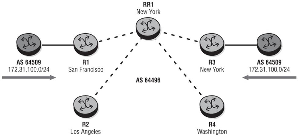
This situation becomes more acute when Route-Reflectors are deployed in a centralized or semi-centralized architecture. Solutions such as ADD-PATH would help here by increasing path visibility to the client. In the example of Figure 11-2, RR1 in New York would have advertised the prefix 172.31.100.0/24 twice; once with a BGP Next-Hop of R1 and once with a Next-Hop of R3. Router R2 then would run its own best-path selection algorithm and select R1 as the preferred Next-Hop. The only issue with ADD-PATH is that it has the potential to push a significant amount of BGP state back to the edge.
Optimal Route Reflection (ORR)
BGP Optimal Route Reflection (draft-ietf-idr-bgp-optimal-route-reflection) proposes a couple of solutions that can be used to resolve this problem. The first proposal is “Best path selection for BGP hot potato routing from client's IGP network position.” The second proposal is “Angular distance approximation for BGP warm potato routing.”
Best Path Selection for Hot Potato Routing from Client's IGP Network Position
As previously discussed, if a Route-Reflector makes a best-path decision based on IGP distance to the BGP Next-Hop, it is based on its own IGP distance to the Next-Hop as opposed to the client's IGP distance. This proposal outlines a solution whereby if IGP metric is the tie-breaker used between a set of paths, the Route-Reflector calculates the IGP metric to the BGP Next-Hop from the position of the client, or clients, to which the resulting path will be advertised. If a hierarchical IGP is in place, the Route-Reflector computes the distance to the BGP Next-Hop from the Area Border Router (ABR) or Level-1/2 router to provide a best-guess approximation of IGP metric. In the presence of hierarchy, an assumption is also made that the Route-Reflectors are placed in the core (area 0/level2) of the network.
The Route-Reflector optionally could implement an IGP distance tolerance value. The purpose of this tolerance value is to make differences in IGP metric invisible to the path selection algorithm if they fall within a certain window. This provides two advantages:
i. It increases the chance that the same path is advertised to a higher number of clients, which in turn optimizes RIB-OUT processing.
ii. It can reduce churn when the IGP topology changes.
To further help optimize workload on the Route-Reflector, it may be possible to group a set of clients. Using this approach, instead of computing IGP distance to the BGP Next-Hop for each individual client, the IGP distance is computed for a group of clients. This grouping could be configured statically on the client and conveyed to the Route-Reflector using an optional parameter in the OPEN message to allow a client to indicate to the Route-Reflector its Group ID value. This allows the Route-Reflector to automatically group peers for the purpose of optimizing RIB-OUT processing.
Angular Distance Approximation for Warm Potato Routing
An alternative proposal involves modeling the network topology as a set of elements (such as regions, POPs, or routers) arranged in a circle where the north of the circle is 0 degrees. The operator works out the angular position of the Route-Reflector clients and inter-domain exit points in the network. The Route-Reflector then modifies its best-path selection algorithm based on the client's angular position versus the angular position of the inter-domain exit points advertising the destination prefix.
Using Figure 11-2 as an example, assume that routers R1, R2, R3, and R4 are all egress points of the Autonomous System, and the Route-Reflector is configured with the set of angular positions listed in Table 11.2.
Table 11.2 Egress Point Angular Positions

Now assume that there are two Route-Reflector clients, one in Miami and one in Seattle. The client in Miami has an angular position of 125, while the client in Seattle has an angular position of 310. The resulting angular distances for those clients versus the egress points can thereafter be calculated as shown in Table 11.3.
Table 11.3 Angular Distances for Clients versus Egress Points
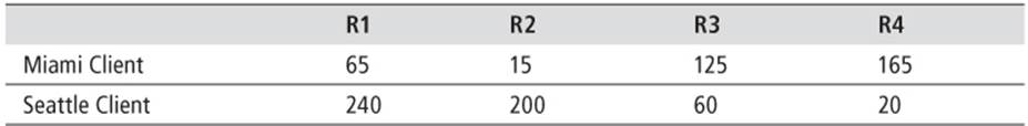
When a Route-Reflector is modified to use the angular distance from the client to the Next-Hop for its best-path selection algorithm, rather than use the IGP distance to the Next-Hop as the tie-breaker, each client is provided with its closest path calculated on the angular positions of the client versus the angular position of the AS egress points as configured by the operator. The term “warm potato” routing is used because the coarseness of angular positions is selectable by the operator. Very granular angular positions result in very little optimization in UPDATE processing toward clients. Conversely, very coarse angular positions allow for grouping of clients and subsequent optimization in UPDATE processing.
Both mechanisms appear to have advantages and disadvantages. Calculating the IGP distance from the client's network position appears to offer a more “hands-off” approach with minimal configuration effort, but Angular Distance Approximation doesn't need to approximate (any further) in the presence of IGP hierarchy. In general, ORR offers a solution when “hot potato” routing is a requirement and the control-plane-only Route-Reflectors have a view of the IGP that is completely different from that of the client. In the absence of ORR, if the control-plane-only Route-Reflectors are cost-effective, it may be easier to distribute them. If centralizing them is a necessity, some fairly complex/heavy-touch workarounds are needed to provide IGP visibility similar to that of the client. This could involve, for example, implementing tunneling techniques, such as GRE or MPLS pseudowires, between the Route-Reflectors and the region or POP that it serves, creating a logical point-to-point interface through which the IGP can run. Or perhaps it could involve static-routing on the control-plane-only Route-Reflectors to BGP Next-Hops using relative metrics.
Prefix Origin Validation
Prefix Origin Validation (draft-ietf-sidr-pfx-validate) is a mechanism that allows a router to validate the origination AS of BGP routes in order to prevent malicious or unintentional prefix misannouncing and take the appropriate action based upon validation or nonvalidation of that prefix. To do this, the router must look at the originating AS in the AS_PATH together with the advertised prefix and validate that the AS number claiming to originate the prefix is in fact authorized to do so.
The validation mechanism employs the Resource Public Key Infrastructure (RPKI) to build a database of IP addresses and AS numbers that can be formally verified. It uses three main components that enable cryptographic validation that an Autonomous System is authorized to originate routes to a given prefix:
i. An X.590 PKI which uses extensions to X.509 (RFC 3779) to encode IP addresses and AS numbers in resource certificates
ii. Separate digitally signed objects called Route Origin Attestations (ROAs) that define the associations between ASNs and IP address blocks
iii. A distributed repository system (caches) that allows for distribution of the information
The distributed repository system employs a three-level structure. The Global RPKI is at the top level of the hierarchy and contains the authoritative data published in a distributed set of servers (RPKI publication repositories) such as IANA, RIRs, and ISPs. Local Caches sit below the Global RPKI in the hierarchy and have a secure transport channel to receive the verified cache from one or more authoritative caches. At the bottom of the hierarchy, routers establish a connection to one or more caches and use a dedicated RPKI-Router protocol (RFC 6810) to initially receive a validated cache, and then receive incremental updates to that cache. To protect from “man-in-the-middle” attacks between the router and RPKI cache, the session uses SSHv2, TCP MD5, or IPSec as a level of protection.
For each cache connection, the router maintains the IP address/fully qualified domain name of the cache, any needed public key of the cache, any needed private key or certificate for itself, and a preference to indicate which cache is preferred in the event that the router is configured to peer with a number of caches. To ensure that the router has an up-to-date version of the cache, each PDU sent from the cache to the router has a serial number. The router then periodically sends the serial number of the highest numbered data it has received from the cache, and the cache responds with all data records that have serial numbers higher than the router's query. In addition, when the cache updates its own database, it sends a Notify message to all of its configured peers as a hint to poll for an update.
When a BGP speaker loads validated objects from the cache into local storage, they are objects with the content {IP address, prefix length, maximum length, origin AS number}, each termed a “Validated ROA Payload” (VRP). When the speaker subsequently receives an UPDATE message from an external peer, the rightmost AS number in the AS_PATH attribute (origin AS) and the prefix are examined and one of three validation states is derived:
|
NotFound |
No VRP covers the route in the UPDATE. |
|
Valid |
At least one VRP matches the route in the UPDATE where the prefix in the UPDATE is either identical to the VRP prefix or a more specific of the VRP prefix. |
|
Invalid |
At least one VRP is found for the route in the UPDATE, but there is no matching ROA where the origin AS matches the origin AS in the AS_PATH, or the prefix in the UPDATE is longer than the maximum length specified in the VRP. |
When a BGP speaker supports prefix origin validation, the BGP decision process is modified so that an additional validation step is performed before any of the standard best path decision process. The additional step simply states that when comparing a pair of routes for a BGP destination, the route with the lowest “validation state” is preferred.
To avoid every router in an Autonomous System peering with RPKI caches, the validation state identified by externally peering routers optionally may be propagated into the Autonomous System using an opaque Origin Validation State Extended Community attribute (draft-ietf-side-origin-validation-signaling) where the last octet of the attribute encodes the route's validation state (0 = valid, 1 = not found, 2 = invalid).
Link State Information Distribution Using BGP
The contents of a link-state database (such as reservable bandwidth, per-CoS reservations, metrics and SRLGs) are in general constrained to an IGP area. If a router wants to compute an end-to-end path across multiple IGP areas (or levels), the Traffic Engineering Database (TED) contains the TE attributes only for the area that the computing router belongs to. The router has no visibility of the topology of the adjacent area(s), so it relies on a method known as “loose-hop” expansion. Using this approach the computing router completes the RSVP Explicit Route Object (ERO) to the first ABR, and then defines a “loose hop” to the next ABR or destination PE. It is then up to the ABR to use “ERO expansion” to compute the hops between the ABR and the next loose hop. This method works, but it provides no way for the head end of the LSP to compute an end-to-end path using a constrained SPF.
The intention of BGP-LS (sometimes referred to as BGP-TE) is to provide the ability to distribute link and node information of a network topology between BGP speakers. The purpose would be to provide real-time Traffic Engineering information to BGP speakers in other Autonomous Systems, or more likely centralized policy servers such as an Application Layer Traffic Optimization (ALTO) Server or Path Computation Element (PCE) that could make informed and optimal end-to-end path computation decisions regardless of inter-AS or inter-area boundaries.
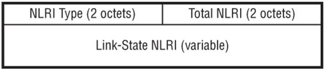
The link state information is distributed using a new Link State NLRI that has the format shown in Figure 11-3, with an additional 8-byte Route-distinguisher field used for distribution of SAFI 128 (VPN) link-state information. The NLRI Type field contains one of two values:
· Type 1 is a Link NLRI containing link descriptors and link attributes.
· Type 2 is a Node containing node attributes.
Figure 11-3 SAFI 1 Link-State NLRI
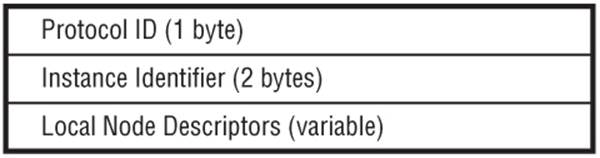
The Link NLRI has the format shown in Figure 11-4 while the Node NLRI has the format shown in Figure 11-5. The Protocol ID identifies the protocol from which the link-state information was obtained (for example, IS-IS or OSPF), while the Instance field identifies a particular instance of that protocol (in case the router is running multiple instances). The Node and Link Descriptor fields contain information identifying a given node/link encoded as TLVs.
Figure 11-4 Link NLRI (NLRI Type 1)
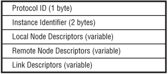
Figure 11-5 Node NLRI (NLRI Type 2)
Node Descriptor TLVs are used to describe the pair of routers that “anchor” a given link. Many types of Router-ID formats are possible, but there must be at least one “like” Router-ID pair of a Local Node Descriptor and Remote Node Descriptor per protocol. The Link Descriptor TLVs uniquely identify a link between two routers, where both sides of the link must advertise a corresponding NLRI for it to be considered valid.
Table 11.4 Descriptor Sub-TLVs
|
TLV |
Type |
Sub-TLV |
|
Node Descriptor |
258 |
Autonomous system |
|
259 |
Member-AS |
|
|
260 |
IPv4 Router-ID |
|
|
261 |
IPv6 Router-ID |
|
|
262 |
ISO Node ID |
|
|
Link Descriptor |
263 |
Link Local/Remote Identifiers |
|
264 |
IPv4 Interface Address |
|
|
265 |
IPv4 Neighbor Address |
|
|
266 |
IPv6 Interface Address |
|
|
267 |
IPv6 Neighbor Address |
|
|
268 |
Multi-Topology ID |
In addition to the NLRI, an optional non-transitive Link-State attribute is used to carry link and node link-state parameters and attributes. This attribute should be used only with the Link State NLRI. It encodes attributes in TLVs using the same format and semantics used in IS-IS Extended IS Reachability sub-TLVs (although some additional values are also used).
Table 11.5 Link Attribute TLVs
|
Type |
Description |
|
269 |
Administrative Group (color) |
|
270 |
Maximum link bandwidth |
|
271 |
Maximum reservable link bandwidth |
|
272 |
Unreserved bandwidth |
|
273 |
Link Protection Type |
|
274 |
MPLS Protocol Mask |
|
275 |
Metric |
|
276 |
Shared Risk Link Group |
|
277 |
OSPF specific link attribute |
|
278 |
IS-IS specific link attribute |
|
279 |
Area ID |
All materials on the site are licensed Creative Commons Attribution-Sharealike 3.0 Unported CC BY-SA 3.0 & GNU Free Documentation License (GFDL)
If you are the copyright holder of any material contained on our site and intend to remove it, please contact our site administrator for approval.
© 2016-2025 All site design rights belong to S.Y.A.