Versatile Routing and Services with BGP: Understanding and Implementing BGP in SR-OS (2014)
Chapter 2. BGP/MPLS IP-VPN
The framework for building BGP/Multi-Protocol Label Switching (BGP/MPLS) based IP Virtual Private Networks (IP-VPNs) relies on Multi-Protocol BGP (RFC 4760) and the optional-transitive BGP Extended Communities (RFC 4360) attribute “Route Target.”
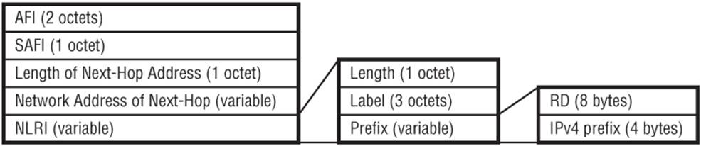
Multi-Protocol BGP is used for advertising of VPN-IPv4/VPN-IPv6 prefixes, and, because both are labeled prefixes, they follow the encoding of labeled BGP (RFC 3107), where the prefix is constructed of an 8-byte Route-Distinguisher followed by a 4-byte IPv4 prefix or 16-byte IPv6 prefix. The purpose of the RD is to allow the concatenation of RD and IPv4/IPv6 prefixes to create a unique VPN-IPv4/VPN-IPv6 prefix.
For VPN-IPv4 the AFI is 1 (IPv4), and for VPN-IPv6 the AFI is 2 (IPv6). Both VPN-IPv4 and VPN-IPv6 use a SAFI of 128 (MPLS-labeled VPN address).
Figure 2-1 VPN-IPv4/IPv6 NLRI Encoding
When a route is redistributed into VPN-IPv4, a Route Target Extended Community is appended to the prefix. The Route Target Extended Community is a transitive attribute (RFC 4360) used to define the set of sites belonging to a given VPN. When a VPN-IPv4 prefix is received at a Provider Edge (PE) router, it parses the Route Target value and checks whether any locally configured VRFs have an import policy that matches that value. If it does, the route is imported into that VPRN. If it doesn't, the route is not imported into any VPRNs. In short, associating a particular Route Target attribute with a prefix allows that route to be placed into VRFs serving that VPN. If ten sites in a VPN all have a common export and import Route Target value, the result is an “any-to-any” VPN.
Basic Configuration
Output 2-1 shows the base level of configuration required in order to configure a VPRN. The route-distinguisher (RD) is a required parameter when configuring a VPRN, and the VPRN will not become operational until it is configured. When a VPRN is configured with a Route-Distinguisher but without any Route Target parameters, the VPRN does not rely on any BGP/MPLS IP-VPN control plane for learning prefixes but simply creates a separate routing context frequently referred to as “VRF-lite.” The route-distinguisher command is followed by a value that can take three formats but typically uses the type 0 format of a 2-byte ASN subfield followed by a 4-byte assigned number subfield (the remaining 2 bytes are used to define the actual type).
To participate in the BGP/MPLS IP-VPN control plane, the definition of Route Target values is required for import and export of VPN-IPv4 prefixes. The simplest method is using the vrf-target command followed by a Route Target value that has the same format as the Route Distinguisher. The vrf-target command allows for definition of a single value applicable to import and export Route Targets as shown in Output 2-1, or it allows for definition of different import and export Route Target values using the export and import keywords after the vrf-target command, followed by the relevant Route Target values. An alternative to the vrf-target approach for defining Route Target values is to use the vrf-import and vrf-export commands to reference policies constructed within the policy framework.
When prefixes are learned in VPN-IPv4, the receiving PE router must resolve the BGP Next-Hop to a GRE or MPLS tunnel before the prefix is considered valid. The auto-bind command tells the system to automatically bind the Next-Hop to an LSP in the LSP tunnel-table, and the keywordmpls means to use any form of LSP, with a preference for RSVP over LDP, and LDP over BGP.
Output 2-1: VPRN Base Configuration
service
vprn 4001
autonomous-system 64496
route-distinguisher 64496:4001
auto-bind mpls
vrf-target target:64496:4001
no shutdown
One last optional parameter is the definition of an autonomous-system number in the VPRN. This parameter is required only if BGP is used as a PE-CE routing protocol. This parameter is used as the source ASN in the OPEN exchange unless the local-as parameter is also configured, in which case the ASN defined as the local-as is used in the OPEN exchange. (This also applies to the use of local-as in the global BGP context.)
At face value, both the VPRN autonomous-system ASN and local-as ASN appear to serve the same purpose of mimicking an ASN that differs from the global ASN defined in the router context. In fact, they can have different impacts on the AS_PATH of UPDATE messages propagated to connected CE routers depending on two things:
· Their co-existence in configuration
· Whether the no-prepend-global-as argument is specified as part of the local-as definition
If configured on their own (they do not co-exist) the VPRN-level ASN or local-as ASN is appended to the AS_PATH advertised to the CE and overrides the global ASN. If they are configured to co-exist, the behavior differs depending on the setting of the local-as no-prepend-global-asparameter. If the no-prepend-global-as parameter is disabled, the local-as AS number is appended to the AS_PATH along with the VPRN-level AS number if it differs from the VPRN-level ASN. If the no-prepend-global-as parameter is enabled, the local-as AS number overrides the VPRN-level AS number.
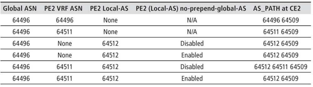
The local-as parameter can be considered useful if a VPRN context needs to appear to be more than one ASN to its peers. If not, the VPRN-level ASN is sufficient. To consolidate the various options, consider the topology in Figure 2-2 where CE1 is in AS 64509 and advertises IPv4 prefix 172.31.100.0/24 to PE1, which in turn propagates the prefix to PE2, which in turn propagates the prefix to CE2. The AS_PATH as seen at CE2 with different configurations is shown in Table 2.1.
Figure 2-2 AS_PATH Encoding
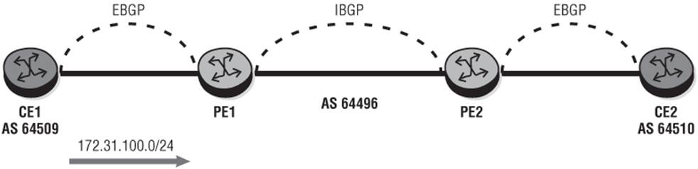
Table 2.1 AS_PATH Encoding with VRF ASN and Local-AS
Prefix Dissemination
When a PE router belongs to a particular VPN, it learns some of that VPN's routes from attached CE routers using static or dynamic routing. These routes are installed in the VRF associated with that CE router and are converted to VPN-IPv4/IPv6 routes for export into BGP so that other PEs belonging to that VPN can learn those routes. These routes can be disseminated to other PE routers of the same VPN through a number of methods; some use an implicit flood model while others use an explicit send-only-if-required model. This section discusses the varying approaches that can be adopted for both prefix dissemination and route-table updates following a local policy change.
Automatic Route Filtering
To help scale BGP/MPLS based IP-VPNs, PE routers do not by default retain in the RIB-IN prefixes that are not associated with any configured VRFs. When a PE router receives a VPN-IPv4/IPv6 prefix with a Route Target value that is not associated with any VRFs on that PE, the prefix is simply discarded (unless, of course, the PE is a Route-Reflector). This approach is known as Automatic Route Filtering (ARF) and ensures that PE routers hold routes only for VRFs that are actually configured on that PE. It is enabled by default and requires no configuration. In the example illustrated in Debug 2-1, the PE router receives VPN-IPv4 prefix 64496:30:172.16.100.0/24 with Extended Community Route Target 64496:30 but has no configured VRFs with that Route Target value. The PE router therefore silently discards the prefix as shown in Output 2-2.
Debug 2-1: Automatic Route Filtering
1 2013/04/22 15:29:36.77 UTC MINOR: DEBUG #2001 Base Peer 1: 192.0.2.11
"Peer 1: 192.0.2.11: UPDATE
Peer 1: 192.0.2.11 - Received BGP UPDATE:
Withdrawn Length = 0
Total Path Attr Length = 75
Flag: 0x90 Type: 14 Len: 32 Multiprotocol Reachable NLRI:
Address Family VPN_IPV4
NextHop len 12 NextHop 192.0.2.13
172.16.100.0/24 RD 64496:30 Label 262139
Flag: 0x40 Type: 1 Len: 1 Origin: 0
Flag: 0x40 Type: 2 Len: 0 AS Path:
Flag: 0x40 Type: 5 Len: 4 Local Preference: 100
Flag: 0x80 Type: 9 Len: 4 Originator ID: 192.0.2.13
Flag: 0x80 Type: 10 Len: 4 Cluster ID:
192.0.2.11
Flag: 0xc0 Type: 16 Len: 8 Extended Community:
target:64496:30"
Output 2-2: ARF and RIB-IN
*A:PE1# show router bgp routes vpn-ipv4 172.16.100.0/24
==========================================================================
BGP Router ID:192.0.2.22 AS:64496 Local AS:64496
==========================================================================
Legend -
Status codes : u - used, s - suppressed, h - history, d - decayed, * - valid
Origin codes : i - IGP, e - EGP, ? - incomplete, > - best, b - backup
==========================================================================
BGP VPN-IPv4 Routes
==========================================================================
Flag Network LocalPref MED
Nexthop Path-Id Label
As-Path
--------------------------------------------------------------------------
No Matching Entries Found
==========================================================================
Route Refresh
ARF is useful for optimizing memory consumption, but what happens if a PE router's policy changes, and it now requires a VPN-IPv4 prefix that it had previously discarded? What is needed is a mechanism to allow the PE router to reevaluate all learned routes against the modified policy. This is the purpose of Route Refresh. Route Refresh (RFC 2918) capability is negotiated during the OPEN exchange and allows a BGP speaker to dynamically request a readvertisement of the Adj-RIB-OUT from a BGP peer. Once the peer readvertises the Adj-RIB-OUT, it can be reevaluated against the new policy. In SR-OS, every time a VPRN import policy is modified, either through the route-policy framework or through modification of the VPRN vrf-target syntax, a Route Refresh is generated for the VPN-IPv4 and VPN-IPv6 Address Families as shown in Debug 2-2. Not shown for conciseness is the Adj-RIB-OUT readvertised to the speaker generating this refresh.
Debug 2-2: Route Refresh
2 2013/04/22 15:41:49.81 UTC MINOR: DEBUG #2001 Base Peer 1: 192.0.2.11
"Peer 1: 192.0.2.11: ROUTE REFRESH
Peer 1: 192.0.2.11 - Send BGP ROUTE REFRESH: Address Family AFI_IPV4: Sub
AFI SAFI_VPN"
3 2013/04/22 15:41:49.81 UTC MINOR: DEBUG #2001 Base Peer 1: 192.0.2.11
"Peer 1: 192.0.2.11: ROUTE REFRESH
Peer 1: 192.0.2.11 - Send BGP ROUTE REFRESH: Address Family AFI_IPV6: Sub
AFI SAFI_VPN"
When the Route Refresh has been generated, all triggered routes (in this case VPN-IPv4 and VPN-IPv6) are marked as “stale” and must be refreshed within the system “purge timer.” By default, this timer is set to 10 minutes, and any prefixes not refreshed before the expiration of the purge timer are deleted. There should be no requirement to modify this timer but it is possible using the purge-timer command within the BGP context.
Route Refresh provides a dynamic way to refresh policy, but the method that it uses can be considered somewhat sub-optimal because the mechanism essentially says to its peer(s) “give me every prefix again and I will reevaluate all of those prefixes against my new RIB-IN policy.” This consumes resources not only for the receiving PE, but also for the peer(s) that need to transmit all of the Adj-RIB-OUT UPDATE messages again. In environments with high provisioning activity, these Route Refreshes can be frequent and often overlapping (which causes the purge timer to be reset again) resulting in a high control plane load. Less of an issue, but still worth highlighting, is that the age of any refreshed prefixes is reset when the route is refreshed. The age of a prefix in a routing table is often used by operational communities when troubleshooting, so having this reset during a Route Refresh means potentially useful information is lost.
Outbound Route Filtering
Where the Route Refresh mechanism refreshes all prefixes of a given Address Family, a better approach could be to ask only for those prefixes a PE router knows that it needs. This is the premise of Outbound Route Filtering (ORF). ORF allows a BGP speaker to send to a BGP peer a set of filters that the peer should apply on its Adj-RIB-OUT.
ORF entries are carried within Route Refresh messages and are encoded as:
· AFI/SAFI, defining the NLRI type
· ORF-type, defining the content of the ORF-value
· Action, defining whether to add or remove the filter
· A match statement in the form of permit or deny (where a permit asks the peer to send the set of routes that match the signaled ORF entry)
SR-OS supports the Extended Community (Route Target) ORF-type and it is enabled by configuring the outbound-route-filtering context followed by the command extended-community and an option or either accept-orf or send-orf. In a typical BGP/MPLS IP-VPN environment involving Route Reflection, PE routers are configured to send-orf values, while Route-Reflectors are configured to accept-orf values. This causes the Route-Reflector(s) to apply filters to its Adj-RIB-OUT such that only requested Route Target values are advertised to its peers.
After ORF has been enabled, any time the VPRN import policy is modified (again either through the route-policy framework or through modification of the VPRN vrf-target syntax), Route Refresh messages are generated that remove any existing filter policy and then apply the modified filter policy. The simple example shown in Debug 2-3 shows a VPRN import policy being created to allow Route Target 64496:20.
Output 2-3: ORF Configuration
router
bgp
outbound-route-filtering
extended-community
accept-orf|send-orf
exit
exit
no shutdown
exit
exit
Debug 2-3: Route-Refresh with ORF
25 2013/04/22 16:27:36.17 UTC MINOR: DEBUG #2001 Base Peer 1: 192.0.2.11
"Peer 1: 192.0.2.11: ORF
Peer 1: 192.0.2.11 - Send BGP (ROUTE_REFRESH) ORF: AFI 1, Sub AFI 128
When-to-refresh: DEFER
ORF Type: Extended Community
ORF Len: 1 Bytes
ORF Action: REMOVE-ALL
ORF Match: PERMIT
"
26 2013/04/22 16:27:36.17 UTC MINOR: DEBUG #2001 Base Peer 1: 192.0.2.11
"Peer 1: 192.0.2.11: ORF
Peer 1: 192.0.2.11 - Send BGP (ROUTE_REFRESH) ORF: AFI 1, Sub AFI 128
When-to-refresh: IMMEDIATE
ORF Type: Extended Community
ORF Len: 9 Bytes
ORF Action: ADD
ORF Match: PERMIT
Extended Community : 0.2.0.64496.0.0.0.20
ORF allows for implementation of a more explicit “request only what you need” model, but support of different ORF-types varies between vendors. For example, SR-OS supports the Extended Community ORF-type, but other implementations have historically favored Address-based ORF-type.
Soft Reconfiguration
One potential way to completely avoid the use of Route Refresh is through the use of the so-called “soft reconfiguration.” Using soft reconfiguration, the router retains all of the Multi-Protocol BGP prefixes that it receives, regardless of whether they are imported into a VRF or not. For prefixes that are imported into a VRF, normal behavior applies, but prefixes with Route Target values that are not associated with any VRF on the router are retained in the RIB-IN and marked as invalid/rejected. Thereafter, when local policy on the router is modified, it does not send any Route Refresh messages but simply scans the prefixes in the RIB-IN against the modified policy.
Soft reconfiguration for BGP/MPLS IP-VPN is enabled with the mp-bgp-keep command under the global BGP context. The advantages over Route Refresh should be self-evident, but the significant disadvantage is that memory is consumed by prefixes that the router doesn't need. If memory is not an issue, soft reconfiguration is a good mechanism for reducing control plane activity.
Route Target Constraint
Constrained Route Target distribution for BGP/MPLS IP-VPNs (RFC 4684) builds on the concept of cooperative route filtering by propagating required Route Target membership information. Route Target membership information received by BGP speakers is then used to dynamically build outbound filters so that VPN-IPv4/IPv6 UPDATE messages are propagated only to peers that have advertised the respective Route Target. In effect, Route Target Constraint is used to create a controlled flooding distribution graph.
The ability to exchange Route Target membership information is negotiated as a capability during the OPEN exchange. Route Target membership NLRI is subsequently advertised using Multi-Protocol BGP (AFI 1, SAFI 132) and contains a prefix between 0 and 96 bits in length of the form {origin-as number, route-target}. A “default” Route Target is also defined, which is encoded as a zero-length prefix. The default Route Target is used to indicate to a peer that this BGP speaker is willing to receive all VPN-IPv4/IPv6 prefixes regardless of Route Target value, and may be used, for example, between a Route Reflector and a client. After exchange of Route Target membership information, a given VPN-IPv4/IPv6 prefix is advertised to a peer only if that peer has advertised either the default Route Target membership NLRI or a Route Target membership NLRI containing any of the targets contained in the extended communities attribute of the VPN-IPv4/IPv6 prefix in question.
For inter-AS scenarios, the encoding of Route Target membership information to include origin-as number allows for adoption of the conventional best-path selection algorithm (including AS_PATH) to build a distribution tree that includes only ASs that are either directly supporting a given VPN or are in the shortest inter-AS path between those ASs supporting that given VPN. This is based on the premise that Inter-AS BGP speakers select the best path for the Route Target Membership NLRI, and subsequently only advertise VPN-IPv4/IPv6 UPDATEs in the inverse direction of that best-path distribution tree.
For intra-AS scenarios however, multiple routers may advertise the same {origin-as number, route-target} Route Target Membership NLRI. To ensure the correct distribution tree is built, you must consider all available IBGP paths for a given RT prefix when building the outbound route filter, and not just the best path. In addition, when advertising Route Target membership information sourced by the local AS to an IBGP peer, BGP attributes are modified as follows:
1. When advertising Route Target membership NLRI to a Route-Reflector client, the originator attribute should be set to the router-ID of the advertising router, and the Next-Hop attribute should be set to the local address of that IBGP session. This is so that the originator of a Route Target Membership NLRI does not drop a Route Target Membership NLRI reflected back to it. In addition, this allows the Route-Reflector to use this Route Target Membership NLRI to instruct the client what VPN routes it should advertise toward the Route-Reflector.
2. When advertising Route Target membership NLRI to a non-client peer, if the best path is a route received from a non-client peer and an alternative path exists from a client, the attributes of the client path are advertised to the peer. This allows full propagation of Route Target Membership NLRI throughout the IBGP mesh.
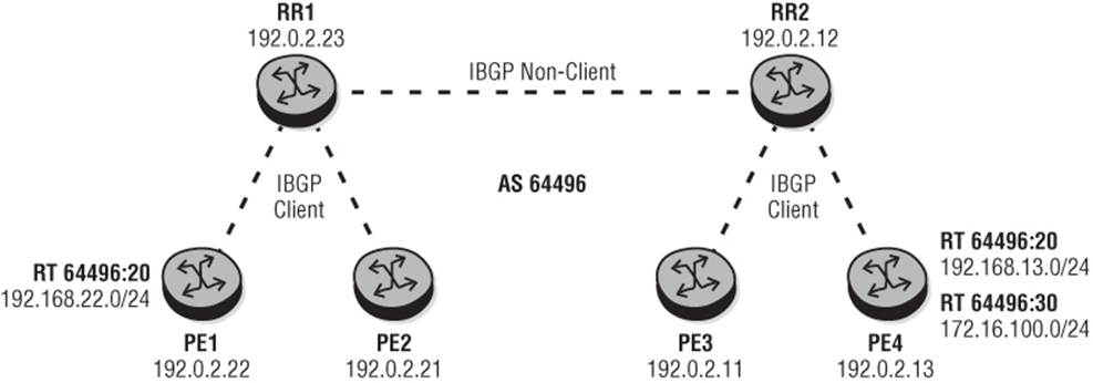
To illustrate the concept, consider the simplistic IBGP topology depicted in Figure 2-3. In this example, PE1 and PE2 are IBGP clients of RR1 while PE3 and PE4 are IBGP clients of RR2. RR1 and RR2 have a non-client peering session between them. Only PE1 and PE4 are supporting VPRN services. PE1 has a single VRF with Route Target 64496:20 with prefix 192.168.22.0/24, while PE4 has two VRFs: Route Target 64496:20 with prefix 192.168.13.0/24 and RT 64496:30 with prefix 172.16.100.0/24.
Figure 2-3 RT Constraint Example Topology
To enable RT Constraint, all you need from a PE perspective is to enable the route-target Address Family. This ensures that Route Target Membership NLRIs are generated for all supported VPRNs on the router. From a Route-Reflector perspective, there is the optional additional step of signaling the default Route Target to clients using the command default-route-target in order to receive all VPN-IPv4/IPv6 prefixes. An example of this configuration from RR1 is shown in Output 2-4.
Output 2-4: RT Constraint Configuration
bgp
group "RR"
family vpn-ipv4 vpn-ipv6 route-target
peer-as 64496
neighbor 192.0.2.12
exit
exit
group "CLIENT"
family vpn-ipv4 vpn-ipv6 route-target
cluster 192.0.2.23
peer-as 64496
default-route-target
neighbor 192.0.2.21
exit
neighbor 192.0.2.22
exit
exit
With this topology and configuration, you can observe the Route Target membership NLRI advertised/received by PE1. Debug 2-4 shows the RT Membership NLRI generated toward RR-1 with {origin-as 64496, route-target 64496:20}. This is followed by an End of RIB marker (empty NLRI) to indicate that the initial RT membership exchange is complete.
Debug 2-4: PE1 RT Membership NLRI
21 2013/04/23 14:09:43.81 UTC MINOR: DEBUG #2001 Base Peer 1: 192.0.2.23
"Peer 1: 192.0.2.23: UPDATE
Peer 1: 192.0.2.23 - Send BGP UPDATE:
Withdrawn Length = 0
Total Path Attr Length = 47
Flag: 0x90 Type: 14 Len: 22 Multiprotocol Reachable NLRI:
Address Family RTC_V4
NextHop len 4 NextHop 192.0.2.22
[RT-Const-V4] origin-as 64496, Target target:64496:20
Flag: 0x40 Type: 1 Len: 1 Origin: 2
Flag: 0x40 Type: 2 Len: 0 AS Path:
Flag: 0x80 Type: 4 Len: 4 MED: 0
Flag: 0x40 Type: 5 Len: 4 Local Preference: 100"
22 2013/04/23 14:09:43.81 UTC MINOR: DEBUG #2001 Base Peer 1: 192.0.2.23
"Peer 1: 192.0.2.23: UPDATE
Peer 1: 192.0.2.23 - Send BGP UPDATE:
Withdrawn Length = 0
Total Path Attr Length = 7
Flag: 0x90 Type: 15 Len: 3 Multiprotocol Unreachable NLRI:
Address Family RTC_V4
No NLRI present! attr len 3, Must be end-of-rib marker!
"
At PE1 you can see the RT Membership NLRI generated by PE4 with {origin-as 64496, route-target 64496:20} and {origin-as 64496, route-target 64496:30}. Note that as described previously, the Route-Reflector sets the Originator ID and Next-Hop attributes to itself. This is followed by the RT Membership NLRI generated by RR1 with the default route-target {origin-as 0, route-target 0.0:0:0}.
Debug 2-5: PE4 and RR2 RT Membership NLRI
23 2013/04/23 14:09:43.80 UTC MINOR: DEBUG #2001 Base Peer 1: 192.0.2.23
"Peer 1: 192.0.2.23: UPDATE
Peer 1: 192.0.2.23 - Received BGP UPDATE:
Withdrawn Length = 0
Total Path Attr Length = 78
Flag: 0x90 Type: 14 Len: 35 Multiprotocol Reachable NLRI:
Address Family RTC_V4
NextHop len 4 NextHop 192.0.2.23
[RT-Const-V4] origin-as 64496, Target target:64496:20
[RT-Const-V4] origin-as 64496, Target target:64496:30
Flag: 0x40 Type: 1 Len: 1 Origin: 2
Flag: 0x40 Type: 2 Len: 0 AS Path:
Flag: 0x80 Type: 4 Len: 4 MED: 0
Flag: 0x40 Type: 5 Len: 4 Local Preference: 100
Flag: 0x80 Type: 9 Len: 4 Originator ID: 192.0.2.23
Flag: 0x80 Type: 10 Len: 8 Cluster ID:
192.0.2.23 192.0.2.12
"
24 2013/04/23 14:09:43.81 UTC MINOR: DEBUG #2001 Base Peer 1: 192.0.2.23
"Peer 1: 192.0.2.23: UPDATE
Peer 1: 192.0.2.23 - Received BGP UPDATE:
Withdrawn Length = 0
Total Path Attr Length = 42
Flag: 0x90 Type: 14 Len: 10 Multiprotocol Reachable NLRI:
Address Family RTC_V4
NextHop len 4 NextHop 192.0.2.23
[RT-Const-V4] origin-as 0, Target 0.0:0:0
Flag: 0x40 Type: 1 Len: 1 Origin: 2
Flag: 0x40 Type: 2 Len: 0 AS Path:
Flag: 0x80 Type: 4 Len: 4 MED: 0
Flag: 0x40 Type: 5 Len: 4 Local Preference: 100
Flag: 0x80 Type: 9 Len: 4 Originator ID: 192.0.2.23
"
In this very simple topology you can verify that the correct distribution tree has been built by checking how far the VPN-IPv4 prefix 172.16.100.0/24 with RT 64496:30 was propagated (its distribution tree). At RR2, Output 2-5 shows that the prefix was received from PE4 because RR2 sent an RT membership NLRI with the default Route Target requesting all routes. However, as shown in Output 2-6, RR2 does not propagate this VPN-IPv4 prefix toward RR1, and advertises only the RT 64496:20 prefix 192.168.13.0/24.
Output 2-5: RT 64496:30 Propagation from PE4
*A:RR2# show router bgp neighbor 192.0.2.13 vpn-ipv4 received-routes
==========================================================================
BGP Router ID:192.0.2.12 AS:64496 Local AS:64496
==========================================================================
Legend -
Status codes : u - used, s - suppressed, h - history, d - decayed, * - valid
Origin codes : i - IGP, e - EGP, ? - incomplete, > - best, b - backup
==========================================================================
BGP VPN-IPv4 Routes
==========================================================================
Flag Network LocalPref MED
Nexthop Path-Id Label
As-Path
--------------------------------------------------------------------------
*>i 64496:20:192.168.13.0/24 100 None
192.0.2.13 None 262140
No As-Path
*>i 64496:30:172.16.100.0/24 100 None
192.0.2.13 None 262139
No As-Path
--------------------------------------------------------------------------
Routes : 2
==========================================================================
Output 2-6: RT 64496:30 Propagation from RR2
*A:RR-2# show router bgp neighbor 192.0.2.23 vpn-ipv4 advertised-routes
==========================================================================
BGP Router ID:192.0.2.12 AS:64496 Local AS:64496
==========================================================================
Legend -
Status codes : u - used, s - suppressed, h - history, d - decayed, * - valid
Origin codes : i - IGP, e - EGP, ? - incomplete, > - best, b - backup
==========================================================================
BGP VPN-IPv4 Routes
==========================================================================
Flag Network LocalPref MED
Nexthop Path-Id Label
As-Path
--------------------------------------------------------------------------
i 64496:20:192.168.13.0/24 100 None
192.0.2.13 None 262140
No As-Path
--------------------------------------------------------------------------
Routes : 1
==========================================================================
If a BGP speaker no longer wants to receive VPN-IPv4/IPv6 prefixes for a given Route Target, it simply withdraws the Route Target membership NLRI using the MP_UNREACH_NLRI attribute. This triggers all peers to reevaluate their RIB-OUTs to remove this Route Target NLRI.
RT Constraint provides a powerful tool to build a prefix distribution tree. The effectiveness of the distribution tree largely depends on the BGP hierarchy and the sparseness of the VRFs deployed. RT Constraint with densely deployed VRFs on a pair of redundant Route-Reflectors essentially achieves the same function as ORF, so you should give some thought to the BGP topology and service base before considering deployment of RT Constraint.

RT Constraint is fully supported for the VPN-IPv4 and VPN-IPv6 Address Families. For the MVPN, MDT-SAFI, L2-VPN, and MS-PW Address Families, SR-OS generates RT Constraint prefixes but does not filter outbound routes based on received RT Constraint routes for those Address Families.
Extensions for IPv6 VPN (6VPE)
The term 6VPE is widely used to describe an IPv6 VPN using the same architecture defined for BGP-MPLS IP-VPNs with extensions where necessary to include IPv6. The specification allows for delivery of VPN-based IPv6 services over an IPv4 or IPv6 backbone, although the former is almost exclusively used (perhaps because of the immaturity of IPv6 MPLS control plane).
A VPN is referred to as an IPv6 VPN when each site of the VPN is IPv6 capable and is connected to a PE router of the Service Provider over an IPv6 interface. Typically, a site is both IPv4 and IPv6 capable, dictating a requirement for dual-stack operation on the PE and CE. This is not a requirement, however, and single-stack IPv6 is equally possible. Running dual-stack on the PE-CE interface is as simple as configuring an IPv4 address and an IPv6 address as shown in Output 2-7. In this example the interface is configured with just an IPv6 Globally Unique Address (GUA) and the link-local address is automatically generated, but it is equally possible to manually configure the link-local address. Note also the use of 127-bit IPv6 prefixes for PE-CE addressing. This follows the recommendation in RFC 6164 and resolves exposure to IPv6 Neighbor Discovery exploitation (RFC 3756). The use of 126-bit IPv6 prefixes also serves to largely mitigate the same issue and is analogous to the use of 30-bit IPv4 addressing on the PE-CE link.
Output 2-7: Dual-Stack PE-CE Interface
service
vprn 4001
interface "PE-CE" create
address 192.168.0.1/30
ipv6
address 2001:DB8:1B0C:2101::4/127
exit
sap 1/1/3:4001.22 create
exit
exit

The 127-bit PE-CE link IPv6 address is a routable address that appears in the VPRN IPv6 routing table. Link-local addresses are not routable and therefore do not appear in the IPv6 routing table. The consequence of this is that if an operator wants to address a connected or adjacent link-local address, it must be suffixed with the appropriate interface name.
The status of the interface is verified from an IPv4 and IPv6 perspective as shown in Output 2-8. Note that the statically configured 127-bit GUA and self-generated link-local are both in the “preferred” state, meaning that the address is assigned to this interface, and its use is unrestricted (other potential states being “tentative” and “deprecated”).
Output 2-8: Dual-Stack Interface Status
*A:PE1# show router 4001 interface "PE-CE"
==================================================================
Interface Table (Service: 4001)
==================================================================
Interface-Name Adm Opr(v4/v6) Mode Port/SapId
IP-Address PfxState
------------------------------------------------------------------
PE-CE Up Up/Up VPRN 1/1/3:4001.22
192.168.0.1/30 n/a
2001:DB8:1B0C:2101::4/127 PREFERRED
FE80::24E0:1FF:FE01:8/64 PREFERRED
------------------------------------------------------------------
Interfaces : 1
==================================================================
Core Requirements
From the perspective of a Service Provider's core infrastructure, there is very little additional requirement in order to support 6VPE if you're using IPv4 tunneling. All that is required is that PE routers can propagate IPv6 routes using the VPN-IPv6 Address Family. If you need to add this, remember that it must be negotiated as a capability in the OPEN exchange. Therefore, the addition of the VPN-IPv6 Address Family causes the router to send a NOTIFICATION message to its peer, followed by an OPEN message containing the new capability.
Output 2-9: Addition of VPN-IPv6 Address Family
router
bgp
group "IBGP"
family vpn-ipv4 vpn-ipv6
peer-as 64496
neighbor …
One other noteworthy point for delivery of 6VPE is the Next-Hop encoding used by PE routers when IPv6 prefixes are redistributed into VPN-IPv6. Where IPv6 VPN traffic is to be transported to the BGP speaker using IPv4 tunneling (IPv4 MPLS LSPs, GRE, IPSec), the BGP speaker advertises the VPN-IPv6 prefix encoding the Next-Hop as an IPv4-mapped IPv6 address containing the IPv4 address of the advertising router. For example, in Output 2-10, the VPN-IPv6 prefix 2001:DB8:1B0C:2200::/56 is received with a Next-Hop of ::FFFF:C000:020D, which is hex for the advertising PE router's system IPv4 address 192.0.2.13. SR-OS automatically decodes the hex-to-decimal and resolves that IPv4 address to an LSP before declaring the received prefix as valid.
Output 2-10: PE Next-Hop Encoding
*A:PE2# show router bgp routes vpn-ipv6 2001:DB8:1B0C:2200::/56 detail
==================================================================
BGP Router ID:192.0.2.22 AS:64496 Local AS:64496
==================================================================
Legend -
Status codes : u - used, s - suppressed, h - history, d - decayed, * - valid
Origin codes : i - IGP, e - EGP, ? - incomplete, > - best, b - backup
==================================================================
BGP VPN-IPv6 Routes
==================================================================
------------------------------------------------------------------
Original Attributes
Network : 2001:DB8:1B0C:2200::/56
Nexthop : ::FFFF:C000:20D
Route Dist. : 64496:4001 VPN Label : 262131
Path Id : None
From : 192.0.2.13
Res. Nexthop : n/a
Local Pref. : 100 Interface Name : to-PE-21
Aggregator AS : None Aggregator : None
Atomic Aggr. : Not Atomic MED : None
AIGP Metric : None
Connector : None
Community : target:64496:4001
Cluster : No Cluster Members
Originator Id : None Peer Router Id : 192.0.2.13
Fwd Class : None Priority : None
Flags : Used Valid Best IGP
Route Source : Internal
AS-Path : 64510
VPRN Imported : 4001
…output truncated
PE to CE BGP Peering
PE routers learn IPv6 prefixes either locally or through IPv6 BGP (other dynamic mechanisms such as OSPFv3 are possible but not discussed here), and encode them as VPN-IPv6 prefixes for dissemination to other PE routers forming the VPN.
When using BGP for prefix exchange on the PE-CE link, a number of options are available:
i. Use IPv4 peering addresses with support for multiple Address Families (IPv4 and IPv6). The advantage of this approach is that it reduces the number of BGP peers required, but it creates a shared risk between Address Families. (If something goes wrong with a peer, it affects both Address Families.)
ii. Use GUAs for peering with support for a single (IPv6) Address Family. The advantage of this approach is the inverse of approach i); it de-couples the Address Families and peering, but obviously requires more peering sessions where dual-stack is required. It also has the advantage that there is implicit connectivity to the IPv6 Next-Hop and doesn't require policy to modify that Next-Hop. (This point is explained further later in this section.)
iii. Use IPv6 Link-Local Addressing for peering with support for a single (IPv6) Address Family. This approach has largely the same advantages and disadvantages as ii) but has some security benefits because the IPv6 addresses are not reachable off-link. However, even if you use link-layer addressing, IPv6 GUAs are still required if, for example, BFD is to be used for fault-detection (which requires a routable IPv6 address).
To demonstrate the use of 6VPE I'll use the topology depicted in Figure 2-4, where PE1 and PE2 form the BGP-MPLS IP-VPN backbone supporting 6VPE, and CE1 and CE2 represent a dual-stack IPv4/IPv6 customer. To allow for illustration of the use of different PE-CE EBGP peering types, PE1 to CE1 uses a single BGP session supporting the IPv4 and IPv6 Address Families, while PE2 to CE2 uses multiple BGP sessions (IPv4 and IPv6) with a single Address Family per session. Obviously this is not a likely scenario, but it illustrates the potential options.
Figure 2-4 6VPE Example Topology
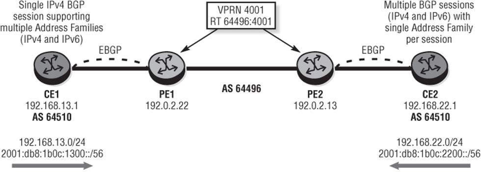
The configuration at PE1 for support of 6VPE is shown in Output 2-11 and shows a single IPv4 peer configured to support the IPv4 and IPv6 Address Families. In addition, because both CE routers belong to AS 64510, any prefixes advertised from CE1 to CE2 or vice versa contain AS 64510 in the AS_PATH attribute. As a result they will be rejected by the receiving CE because of BGP loop prevention. To avoid this situation the as-override command is used to replace any iterations of the configured peer-as in the AS_PATH with the backbone AS number.
The policy applied to the IPv4 neighbor in Output 2-11 is very simple and does enough to redistribute BGP-VPN routes to BGP. Without this policy, routes would not be redistributed between the two Address Families.
From an IPv4 perspective, this policy works just fine. A check of the IPv4 route table on CE1 shows that the IPv4 prefix 192.168.22.0/24 advertised by CE2 has been learned and installed in the route-table with a Next-Hop of PE1 (192.168.0.1).
Output 2-11: PE1 6VPE Configuration (single IPv4 BGP session)
service
vprn 4001
vrf-import "vrf4001-import"
vrf-export "vrf4001-export"
autonomous-system 64496
route-distinguisher 64496:4001
auto-bind ldp
interface "PE-CE" create
address 192.168.0.1/30
ipv6
address 2001:DB8:1B0C:2101::4/127
exit
sap 1/1/3:4001.22 create
exit
exit
bgp
group "EBGP"
as-override
neighbor 192.168.0.2
family ipv4 ipv6
export "ex-ebgp-4001"
peer-as 64510
exit
exit
no shutdown
exit
no shutdown
exit
Output 2-12: PE1 BGP-VPN to BGP Export Policy
*A:PE1# show router policy "ex-ebgp-4001"
entry 10
from
protocol bgp-vpn
exit
to
protocol bgp
exit
action accept
exit
exit
default-action reject
Output 2-13: CE1 IPv4 Route-Table
*A:CE1# show router route-table
==================================================================
Route Table
==================================================================
Dest Prefix[Flags] Type Proto Age Pref
Next Hop[Interface Name] Metric
------------------------------------------------------------------
192.168.0.0/30 Local Local 00h44m12s 0
CE-PE 0
192.168.13.0/24 Local Local 01h22m30s 0
loopback 0
192.168.22.0/24 Remote BGP 00h06m53s 170
192.168.0.1 0
------------------------------------------------------------------
No. of Routes: 3
Flags: L = LFA nexthop available B = BGP backup route available
n = Number of times nexthop is repeated
==================================================================
However, the IPv6 prefix 2001:DB8:1B0C:2200::/56 advertised by CE2 is not seen in the IPv6 routing table. The reason is that the Next-Hop ::CA08:1 is an IPv4-compatible IPv6 address representing PE1's IPv4 PE-CE address which cannot be resolved by CE1. As such, the route is considered Invalid due to Nexthop-Unresolved. The use of an IPv4-compatible IPv6 address in this situation is historic because they are now deprecated (RFC 5156), and using an IPv4-mapped IPv6 address may appear more appropriate. Regardless, however, neither form of IPv6 address type would be resolvable over a PE-CE EBGP peering without some other form of intervention, so it is somewhat irrelevant.
Output 2-14: CE1 IPv6 BGP Routes with Unresolved Next-Hop
*A:CE1# show router bgp routes ipv6 2001:DB8:1B0C:2200::/56 detail
==================================================================
BGP Router ID:192.168.255.13 AS:64510 Local AS:64510
==================================================================
Legend -
Status codes : u - used, s - suppressed, h - history, d - decayed, * - valid
Origin codes : i - IGP, e - EGP, ? - incomplete, > - best, b - backup
==================================================================
BGP IPv6 Routes
==================================================================
------------------------------------------------------------------
Original Attributes
Network : 2001:DB8:1B0C:2200::/56
Nexthop : ::C0A8:1
Path Id : None
From : 192.168.0.1
Res. Nexthop : Unresolved
Local Pref. : n/a Interface Name : NotAvailable
Aggregator AS : None Aggregator : None
Atomic Aggr. : Not Atomic MED : None
AIGP Metric : None
Connector : None
Community : No Community Members
Cluster : No Cluster Members
Originator Id : None Peer Router Id : 192.168.0.222
Fwd Class : None Priority : None
Flags : Invalid IGP Nexthop-Unresolved
Route Source : External
AS-Path : 64496 64496
....output truncated
The solution is quite simple and involves manually setting the Next-Hop on PE1's export policy so that it represents the IPv6 PE-CE address as shown in Output 2-15. This same policy is applicable to redistribute IPv4 prefixes, but the imposition of an IPv6 Next-Hop address has no impact on this Address Family.
Output 2-15: PE1 modified Export Policy
*A:PE1# show router policy "ex-ebgp-4001"
entry 10
from
protocol bgp-vpn
exit
to
protocol bgp
exit
action accept
next-hop 2001:DB8:1B0C:2101::4
exit
exit
default-action reject
Rechecking the IPv6 route-table at CE1, you can see that the IPv6 prefix 2001:DB8:1B0C:2200::/56 advertised by CE2 is correctly installed with the Next-Hop of PE1's IPv6 WAN address as defined in the modified export policy.
Output 2-16: CE1 IPv6 Route-Table with Modified Export Policy
*A:CE1# show router route-table ipv6
==========================================================================
IPv6 Route Table
==========================================================================
Dest Prefix[Flags] Type Proto Age Pref
Next Hop[Interface Name] Metric
-------------------------------------------------------------------------
2001:DB8:1B0C:1300::/56 Local Local 01h37m41s 0
loopback 0
2001:DB8:1B0C:2101::/127 Local Local 00h59m23s 0
CE-PE 0
2001:DB8:1B0C:2200::/56 Remote BGP 00h07m25s 170
2A00:3011:1B0C:2101::4 0
-------------------------------------------------------------------------
No. of Routes: 3
Flags: L = LFA nexthop available B = BGP backup route available
n = Number of times nexthop is repeated
==========================================================================
Output 2-17 shows the configuration at PE2 for support of 6VPE with an IPv4 BGP session supporting the IPv4 Address Family only and an IPv6 BGP session supporting the IPv6 Address Family only. Again, from a configuration perspective, this output requires very little discussion. Moreover, the Next-Hop issues observed with the single IPv4 BGP session at PE1 are not observed here because by default all IPv4 BGP UPDATEs use PE2's IPv4 WAN address and all IPv6 BGP UPDATEs use PE2's IPv6 WAN address.
Output 2-17: PE2 6VPN Configuration (IPv4 and IPv6 BGP sessions)
service
vprn 4001
vrf-import "vrf4001-import"
vrf-export "vrf4001-export"
autonomous-system 64496
route-distinguisher 64496:4001
auto-bind ldp
interface "pe-ce" create
address 192.168.0.5/30
ipv6
address 2001:DB8:1B0C:2101::2/127
exit
sap 1/1/3:4001.13 create
exit
exit
bgp
group "EBGP"
as-override
neighbor 192.168.0.6
family ipv4
export "ex-ebgp-4001"
peer-as 64510
exit
neighbor 2001:DB8:1B0C:2101::3
family ipv6
export "ex-ebgp-4001"
peer-as 64510
exit
exit
no shutdown
exit
no shutdown
At CE2, a check of the respective route-tables in Output 2-18 and Output 2-19 shows that both IPv6 and IPv4 prefixes are learned through each BGP session and are populated into the associated route-tables.
Output 2-18: CE2 IPv6 Route-Table
*A:CE2# show router route-table ipv6
==================================================================
IPv6 Route Table
==================================================================
Dest Prefix[Flags] Type Proto Age Pref
Next Hop[Interface Name] Metric
------------------------------------------------------------------
2001:DB8:1B0C:1300::/56 Remote BGP 01h14m41s 170
2001:DB8:1B0C:2101::2 0
2001:DB8:1B0C:2101::2/127 Local Local 03h14m03s 0
CE-PE 0
2001:DB8:1B0C:2200::/56 Local Local 06h41m59s 0
loopback 0
------------------------------------------------------------------
No. of Routes: 3
Flags: L = LFA nexthop available B = BGP backup route available
n = Number of times nexthop is repeated
==================================================================
Output 2-19: CE2 IPv4 Route Table
*A:CE2# show router route-table ipv4
==================================================================
Route Table
==================================================================
Dest Prefix[Flags] Type Proto Age Pref
Next Hop[Interface Name] Metric
------------------------------------------------------------------
192.168.0.4/30 Local Local 01h59m30s 0
CE-PE 0
192.168.13.0/24 Remote BGP 01h25m17s 170
192.168.0.5 0
192.168.22.0/24 Local Local 02h31m53s 0
loopback 0
------------------------------------------------------------------
No. of Routes: 3
Flags: L = LFA nexthop available B = BGP backup route available
n = Number of times nexthop is repeated
==================================================================
Multi-AS Backbones (Inter-AS)
A Multi-As or Inter-AS IP-VPN is a VPN where the sites belonging to that VPN are connected to different Autonomous Systems. Inter-AS is typically used either to provide extended reach through a partnership/trust agreement, as an interim means to interconnect Autonomous Systems following acquisition, or simply because of the internal organization of a single Service Provider. Three methods of interconnecting Autonomous Systems are outlined in RFC 4364.
A “Type A” interconnect consists of VRF-to-VRF connections at the Autonomous System Border Routers (ASBRs) and is commonly referred to as back-to-back VRFs. From the perspective of the local ASBR, each VRF-to-VRF connection (VLAN or ATM PVC) looks and feels just like a PE to CE connection with route distribution between Autonomous Systems using IPv4/IPv6 BGP. Given the straightforward nature of its implementation, it does not require further discussion.
A “Type C” interconnect involves EBGP redistribution of internal system addresses to the neighboring AS using labeled IPv4 routes. VPN-IPv4 (or VPN-IPv6) routes are thereafter advertised from PEs (or Route-Reflectors) in one AS to PEs (or Route-Reflectors) in the neighboring AS using multi-hop EBGP. At the VPN-IPv4/IPv6 level, Next-Hop IP addresses remain intact (the PE who learns the route from a directly connected CE and sources the VPN-IP prefix), but in order to forward traffic, that Next-Hop address must be resolved to a labeled IPv4 route. Because of its inherent use of labeled IPv4 unicast routes, Type C interconnects are discussed in further detail in Chapter 5.
A “Type B” interconnect involves EBGP redistribution of VPN-IPv4 (or VPN-IPv6) routes from AS to neighboring AS. An ASBR learns VPN routes from within its own AS using IBGP (perhaps as a client of a Route-Reflector) and then uses EBGP to redistribute those labeled VPN routes to its adjacent ASBR. In the process of redistributing the routes into EBGP, the ASBR imposes Next-Hop-Self on the VPN-IPv4/IPv6 UPDATE and generates its own label value when it advertises the UPDATE upstream. This essentially means that the ASBR programs a label-swap entry in its FIB and forwards traffic to the neighboring ASBR using a single-level label stack (the VPN label). A key attribute of a Type B interconnect is that the ASBR does not need to have VRFs explicitly configured. This means, however, that the ASBR must have a mechanism to implicitly learn all VPN prefixes within its own AS and selectively advertise some of those prefixes to the neighboring ASBR.
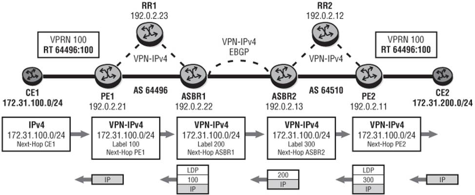
Figure 2-5 gives an example of the control plane and corresponding data plane used in Type B interconnects. The same topology illustrates the configuration requirements for Inter-AS Type B. Here CE1 is attached to PE1 in AS 64496 and advertises prefix 172.31.100.0/24, which is propagated between neighboring ASBRs to PE2 in AS 64510 and then upstream to CE2. The label values are fictitious but are intentionally easy on the eye to aid understanding.
Figure 2-5 Type B Control and Data Plane Example
There are no specific requirements on PE routers or Route-Reflectors in order to enable a Type B interconnect. There are, however, some specific configuration requirements on the ASBRs. Output 2-20 illustrates an example of these taken from ASBR1. The enable-inter-as-vpn command in the global BGP context does two significant things:
· It allows the ASBR to implicitly accept all VPN routes regardless of Route Target value into the RIB-IN, thereby avoiding explicit configuration of VRFs (it is analogous to an “accept all”). These routes are advertised to neighboring ASBRs once they are considered valid, but will of course be subject to RIB-OUT policy.
· The ASBR attempts to resolve the BGP Next-Hop of these IBGP-received VPN routes to an MPLS LSP, and considers a received VPN route as valid only after it has done so. If there is no LSP for the BGP Next-Hop, the route is considered invalid and is not advertised further by the ASBR. By default, SR-OS uses LDP as a transport protocol to attempt to resolve these BGP Next-Hops, but this behavior is configurable using the transport-tunnel command in the global BGP context, which provides options for ldp, rsvp-te, and mpls. The default is ldp, but if RSVP LSPs are in use within the Autonomous System, the transport-tunnel option should reflect rsvp-te. If both RSVP and LDP are in use within the Autonomous System, the option exists to select mpls as a transport-tunnel option. This option tries to use an RSVP LSP first; if no RSVP LSP exists, it attempts to use an LDP LSP.
Within the external group node the vpn-apply-import and vpn-apply-export commands are configured in order to allow global instance BGP import and export policies to be applied to VPN-IPv4/IPv6 routes. The corresponding import/export policies are implemented below that using theimport and export commands while the associated route policies are shown in Output 2-21. The policies are simple in nature and are also symmetric, but illustrate how the policies can be applied. The policies should be completed with a default-action reject not only to ensure that only the specified prefixes are advertised, but also to ensure that MPLS resources are not unnecessarily consumed.
Output 2-20: Type B Interconnect Configuration
router
interface "to-AS64510"
address 192.0.2.49/30
port 1/1/3:100
exit
no shutdown
exit
bgp
enable-inter-as-vpn
group "EBGP"
family vpn-ipv4
vpn-apply-import
vpn-apply-export
import "ASBR-IMPORT"
export "ASBR-EXPORT"
peer-as 64510
neighbor 192.0.2.50
exit
exit
group "IBGP"
family vpn-ipv4
peer-as 64496
neighbor 128.8.72.23
exit
exit
no shutdown
exit
exit
Output 2-21: ASBR VPN-IPv4 Route Policies
router
policy-options
begin
community "to-AS64510" members "target:64496:100"
community "from-AS64510" members "target:64496:100"
policy-statement "ASBR-EXPORT"
entry 10
from
community "to-AS64510"
exit
action accept
exit
exit
default-action reject
exit
policy-statement "ASBR-IMPORT"
entry 10
from
community "from-AS64510"
exit
action accept
exit
exit
default-action reject
exit
commit
exit
The configuration example shown in Output 2-20 uses Ethernet on the ASBR to ASBR interconnect, and for this scenario the configuration shown previously is sufficient. However, if Packet Over Sonet (POS) is used on the ASBR interconnect it requires that MPLS is enabled on the interface. This, in turn, enables RSVP on the interface, although this can be administratively shut down. The reason is that in order for SR-OS to be able to forward labeled packets over the interface, MPLSCP has to be negotiated in PPP Network Control Protocol (NCP), and this requires the interface to be MPLS-enabled.
Referring again to Figure 2-5, ASBR1 has the responsibility of receiving VPN prefixes in IBGP and redistributing them into EBGP and vice versa. At the same time it imposes Next-Hop-Self, generates a new label for the advertised UPDATE, and programs a label-swap entry. When the ASBR forwards traffic into its own Autonomous System, it is also necessary to push on a transport level label (LDP or RSVP) to reach a non-adjacent next hop. The received/advertised BGP labels are programmed on a {Next-Hop, Received Label} basis, as shown in Output 2-22.
Output 2-22: Inter-AS BGP Labels as ASBR1
*A:ASBR1# show router bgp inter-as-label
==================================================================
BGP Inter-AS labels
==================================================================
NextHop Received Advertised Label
Label Label Origin
------------------------------------------------------------------
192.0.2.21 131068 262140 Internal
192.0.2.50 262140 262139 External
------------------------------------------------------------------
Total Labels allocated: 2
==================================================================
The output of show router bgp inter-as labels can be a little difficult to interpret, so I'll add some clarity around this output. Recall that PE1 is advertising VPN prefix 172.31.100.0/24 into IBGP and that ASBR1 has policy that permits this route to be readvertised in EBGP toward ASBR2 in AS 64510. Look at the UPDATE that ASBR1 received from PE1 (192.0.2.21) for VPN-IPv4 prefix 172.31.100.0/24 in Output 2-23; the received label was 131068. Now look at the UPDATE that ASBR1 advertised toward ASBR2 for the same prefix in Output 2-24; the advertised label was 262140. This accounts for the first line of output in theshow router bgp inter-as labels output. The second line is the inverse operation for VPN-IPv4 prefix 172.31.200.0/24 sourced by PE2 in AS 64510, and advertised toward ASBR1 by ASBR2 (192.0.2.50).
Output 2-23: ASBR1 Received Label from PE1
*A:ASBR1# show router bgp neighbor 192.0.2.23 vpn-ipv4 received-routes
=========================================================================
BGP Router ID:192.0.2.22 AS:64496 Local AS:64496
=========================================================================
Legend -
Status codes : u - used, s - suppressed, h - history, d - decayed, * - valid
Origin codes : i - IGP, e - EGP, ? - incomplete, > - best, b - backup
=========================================================================
BGP VPN-IPv4 Routes
=========================================================================
Flag Network LocalPref MED
Nexthop Path-Id Label
As-Path
-------------------------------------------------------------------------
*>i 64496:100:172.31.100.0/24 100 None
192.0.2.21 None 131068
No As-Path
-------------------------------------------------------------------------
Routes : 1
=========================================================================
By default, SR-OS uses a label-per-VRF mode of label distribution. As a result, if PE1 were to advertise another VPN-IPv4 prefix belonging to the same VRF, it would not consume any additional MPLS label resources at ASBR1 because the same label would be signaled and nothing changes in the {Next-Hop, Received Label} tuple. However, if another PE router, say PE3, was added into the VPN and advertised another prefix (or even the same prefix), this would consume additional resources because the Next-Hop and label would be different. Equally, if a second VRF was configured at PE1, this would consume resources because although the Next-Hop would be the same, the advertised label would be different.
Output 2-24: ASBR1 Advertised Label towards ASBR2
*A:ASBR1# show router bgp neighbor 192.0.2.50 vpn-ipv4 advertised-routes
==========================================================================
BGP Router ID:192.0.2.22 AS:64496 Local AS:64496
==========================================================================
Legend -
Status codes : u - used, s - suppressed, h - history, d - decayed, * - valid
Origin codes : i - IGP, e - EGP, ? - incomplete, > - best, b - backup
==========================================================================
BGP VPN-IPv4 Routes
==========================================================================
Flag Network LocalPref MED
Nexthop Path-Id Label
As-Path
--------------------------------------------------------------------------
i 64496:100:172.31.100.0/24 n/a None
192.0.2.49 None 262140
64496
--------------------------------------------------------------------------
Routes : 1
==========================================================================
All materials on the site are licensed Creative Commons Attribution-Sharealike 3.0 Unported CC BY-SA 3.0 & GNU Free Documentation License (GFDL)
If you are the copyright holder of any material contained on our site and intend to remove it, please contact our site administrator for approval.
© 2016-2026 All site design rights belong to S.Y.A.