Versatile Routing and Services with BGP: Understanding and Implementing BGP in SR-OS (2014)
Chapter 5. Labeled Unicast IPv4
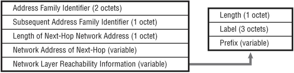
When an UPDATE message carries information about a particular prefix, it is also possible to “piggy-back” MPLS label mapping information for that prefix. The ability to carry label information in BGP (RFC 3107 ) builds on the Multi-Protocol BGP extension MP_REACH_NLRI attribute using AFI 1 (IPv4) with SAFI 4 (NLRI with MPLS labels) to indicate the presence of a label. The NLRI of the MP_REACH_NLRI attribute is encoded as one or more triples in the form <length, label, prefix>.
The output shown in Debug 5-1 gives an example of a MP_REACH_NLRI for a labeled BGP Address Family with prefix 192.0.2.22/32 and label 262138 using the encoding shown in Figure 5-1. A BGP speaker can withdraw a previously advertised prefix and label simply by listing the NLRI of a previously advertised route in the withdrawn routes field of an MP_UNREACH_NLRI attribute. In this case, the label information carried as part of the NLRI should be set to 0.
Figure 5-1 MP_REACH_NLRI Labeled BGP Encoding
Debug 5-1: Labeled BGP Prefix
2 2013/05/16 10:03:57.33 UTC MINOR: DEBUG #2001 vprn100 Peer 2: 192.168.0.2
"Peer 2: 192.168.0.2: UPDATE
Peer 2: 192.168.0.2 - Received BGP UPDATE:
Withdrawn Length = 0
Total Path Attr Length = 41
Flag: 0x90 Type: 14 Len: 17 Multiprotocol Reachable NLRI:
Address Family IPV4-Labeled
NextHop len 4 NextHop 192.168.0.2
192.0.2.22/32 Label 262138
Flag: 0x40 Type: 1 Len: 1 Origin: 0
Flag: 0x40 Type: 2 Len: 6 AS Path:
Type: 2 Len: 1 < 64496 >
Flag: 0x40 Type: 3 Len: 4 Nexthop: 192.168.0.2
"
When using BGP to advertise labels that subsequently will be used in the data-plane for MPLS forwarding, it is important to make a distinction between adjacent and non-adjacent peers. For example, assume that routers R1 and R2 are directly adjacent and that router R2 advertises label L for prefix P to router R1. Thereafter, router R1 can push label L onto an MPLS packet forwarded to R2 without issue. However, now consider the case there are four routers in the topology R1—R2—R3—R4. Routers R4 and R1 are BGP peers and router R4 advertises label L for prefix P to router R1. When R1 subsequently imposes label L onto a packet's label stack, it cannot forward it as top of stack. Rather, it must push on another label so that router R2 sees a label at the top of the stack that it distributed. Similarly, R2 must swap the top label so that R3 sees a label at the top of the stack that it distributed. Router R4 can be the only router that processes label L.
Although this seems fairly obvious, it is worth remembering. The following sub-sections discuss some use-cases for using BGP to advertise MPLS labels. The adjacent peer versus non-adjacent peer scenarios are evident.
Seamless MPLS
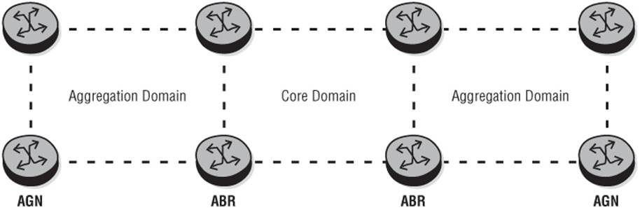
Seamless MPLS (draft-ietf-mpls-seamless-mpls) is a framework that can be used to extend MPLS networks across aggregation and access domains so that the entire network can be considered a single MPLS domain spanning potentially hundreds of thousands of nodes. It does not define any new protocols or technologies but rather relies on existing ones, while taking into account the limited feature-set and scale of smaller aggregation nodes (AGNs) and access nodes (ANs). The architecture uses a “divide and conquer” approach; a large problem is divided into many smaller problems. It builds upon “typical” Service Provider topologies, and hierarchy is a key element. Aggregation domains are never connected to each other, only to the core, while the gateway between the core and aggregation layers is implemented by an Area Border Router (ABR).
Figure 5-2 Seamless MPLS Architecture
The objective of Seamless MPLS is to tackle a number of key issues including scaling to hundreds of thousands of nodes, redundancy and sub-second reconvergence, and providing better network manageability through endpoint-only provisioning across MPLS domains. A key component to all three is that the transport layer is completely decoupled from the service layer.
Transport Layer
Intra-domain routing can be implemented using OSPF or IS-IS, although this overview discusses only IS-IS. Depending on the size of the network and the provider requirements, IS-IS can be either a single instance with multiple levels or multiple instances with single or multiple levels. Where multiple instances are used, the ABR typically implements instance 0 (the default IS-IS instance) toward the core domain, and one or more non-zero instances toward the aggregation domain(s). Either way, the objective is to create smaller and more manageable IGP islands.
Inter-domain routing is achieved using Labeled Unicast BGP to distribute loopback/system addresses between domains. To allow for separation of core/aggregation IGP domains or limited route-leaking between core/aggregation IGP domains, the ABR performs the role of an IBGP Route-Reflector. The notable difference for the ABR is that while advertising the labeled BGP prefix upstream, it imposes Next-Hop-Self and allocates its own downstream label. This effectively puts the ABR into the data-path.
The ABR can implement Next-Hop-Self in the direction of the core only, or in both directions as shown in this example (toward the core and toward the aggregation domain). Both approaches are valid. Implementing Next-Hop-Self toward the core only is used when a single instance of IS-IS is adopted across all domains. The core domain represents Level 2 and the aggregation domains represent Level 1. Loopbacks of ABRs and PEs situated in the core are leaked from Level 2 to Level 1 so that Next-Hops of advertised labeled unicast IPv4 prefixes can be correctly resolved.
Implementing Next-Hop-Self in both directions is used when non-zero instances of IS-IS are used in the aggregation domains. This allows for complete IGP separation between core and aggregation domains with no route-leaking between instances. In situations where multiple aggregation domains connect to the same ABR, multiple non-zero instances can be used to control the size of the link-state database in the AGNs. If a single instance of IS-IS were used in this situation, the aggregation domains connecting to the same ABR would form a contiguous Level-1 link state topology. There is a cost associated with imposing Next-Hop-Self, however. When an ABR sets Next-Hop-Self on a labeled unicast IPv4 prefix, it must allocate a new local label for that prefix and advertise this label to its upstream peers. At the same time, it must program a label-swap entry in the LFIB for the received and advertised labels. Imposing Next-Hop-Self therefore consumes LFIB resources. It should be reasonably clear that when imposing Next-Hop-Self in both directions the rate of consumption is doubled when compared to imposing Next-Hop-Self toward the core only.
An example of a Seamless MPLS topology imposing Next-Hop-Self in both directions is illustrated in Figure 5-3. This figure shows two aggregation domains connected to a core domain, each with its own IGP and each running LDP or RSVP (or both). At the BGP layer, AGN2 advertises its system address to its peer ABR2 with Next-Hop AGN2 and label L1. ABR2 is performing the role of an IBGP Route-Reflector, so it reflects the IBGP-learned prefix from AGN2 to its peer ABR1. It sets Next-Hop-Self on the prefix and allocates a new label L2 so that it can perform a label-swap action between the domains. When the prefix arrives at ABR1, it performs the same function, reflecting the prefix to AGN1, setting Next-Hop-Self, and allocating a new label L3.
Figure 5-3 Seamless MPLS Inter-Domain Routing
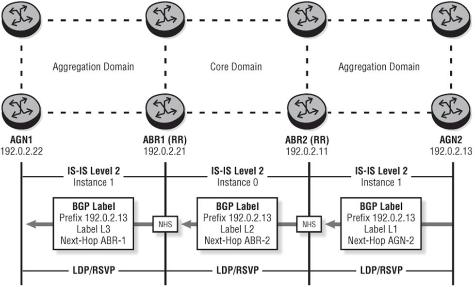
At the transport layer, there is now an end-to-end LSP separated into three discrete islands (remember, service layer signaling including labels is decoupled). If AGN1 needs to get to AGN2, it imposes the BGP-learned label L3 onto the packet followed by an LDP/RSVP label to the Next-Hop ABR1. When the packet arrives at ABR1, it pops the LDP/RSVP label, swaps the BGP labels (L3 to L2), and then imposes the LDP/RSVP label to the Next-Hop ABR2. When the packet arrives at ABR2, it pops the LDP/RSVP label, swaps the BGP labels (L2 to L1), and then imposes the LDP/RSVP label to the Next-Hop AGN2.
You can implement Seamless MPLS in a number of ways, and Figure 5-3 is a relatively simple example of one of them. The example shows only the architecture, including aggregation domains, but another layer of hierarchy could exist from the aggregation domain toward the access domain. The objective is not to list all of the possible design choices with their advantages and disadvantages, but simply to illustrate how labeled BGP is used in this environment to stitch together discrete and manageable “islands.”
Although the IGPs in Figure 5-3 are completely isolated with no route-leaking between them, the potential exists (subject to policy) that a given AGN will receive a labeled BGP prefix for system addresses of all nodes in the network (AN, AGN, ABR, core PE) except pure P nodes. By default, as long as the Next-Hop can be resolved, these prefixes are placed in the FIB, consuming MPLS resources. Whether this is acceptable or not depends on the capabilities of the AGN and the size of the network. However, potential optimizations are possible so that these prefixes are only held in RIB-IN (which is typically larger than the FIB by an order of magnitude) and only downloaded to the FIB when there is active forwarding state.
Output 5-1 and Output 5-2 show an example BGP/policy configuration for ABR1. The example is broken into BGP configuration (Output 5-1) and policy configuration (Output 5-2) for readability, and only the pertinent parts of the configuration are described. The output assumes that IS-IS and MPLS are configured and operational.
Output 5-1: Seamless MPLS ABR Configuration Example
bgp
cluster 192.0.2.11
advertise-inactive
rapid-withdrawal
backup-path ipv4
transport-tunnel mpls
group "IBGP"
family ipv4
export "IPv4-AF"
peer-as 64496
neighbor 192.0.2.1
advertise-label ipv4
exit
neighbor 192.0.2.12
advertise-label ipv4
exit
exit
no shutdown
exit
Within the BGP configuration, the cluster command effectively means that the router is a Route-Reflector and that IBGP peers under this context are Route-Reflector clients. It can be enabled at BGP level, group level, or neighbor level. In this instance, all the peers of ABR-1 are clients, so it is entered at the BGP level. The cluster command is followed by a cluster ID in dotted decimal format, which is populated into the Cluster ID attribute when reflected to clients by the Route-Reflector to avoid cluster loops.
The advertise-inactive command is used to overcome an issue when using labeled BGP to advertise prefixes that are also known by some other protocol such as the IGP. Consider the case in Figure 5-3 where ABR2 receives the labeled BGP prefix for AGN2's system address and needs to advertise this upstream to ABR1. ABR2 learns AGN2's system address in BGP and also IS-IS (Level-2). Because of default route preferences, only the IS-IS learned prefix is installed in the route-table, and the BGP learned prefix remains in RIB-IN, which basically means that ABR2 does not reflect the route upstream. The advertise-inactive command causes the best BGP route (and only the best route) to be advertised even if it is not the most preferred route within the system for a given destination (an IGP route also exists). When the labeled BGP prefix has been advertised, a label swap entry is programmed even though the BGP prefix is inactive.
The backup-path command followed by the keyword ipv4 enables Edge PIC for IPv4, which in this scenario means labeled BGP prefixes and is used to provide for fast reconvergence in the event of ABR failure. (The use of Edge PIC is described in further detail in Chapter 6.) The transport-tunnel command instructs BGP what interface-level MPLS mechanism should be used to resolve the BGP Next-Hop when the peers are non-adjacent. The options are RSVP-TE, LDP, or simply MPLS. The latter means that either RSVP-TE or LDP can be used, with a preference given to an RSVP-TE LSP if it is available.
Finally, each of the neighbor statements is suffixed with the command advertise-label ipv4, which essentially enables the use of labeled BGP for the IPv4 Address Family.
Output 5-2 illustrates the policy referenced at group level in Output 5-1. Entry 10 is required in order to advertise ABR1's system address into labeled BGP, while entry 20 is required in order to set Next-Hop-Self on all labeled BGP prefixes learned from IBGP peers. In reality, the policy is likely to be a little more restrictive about which prefixes are advertised into each domain, but the output still illustrates the minimum requirement.
You have a number of ways to view label values that are advertised for a particular prefix. As you would expect, displaying the RIB-IN as shown in Output 5-3 gives details on advertised prefix and label, together with the Next-Hop and resolved Next-Hop information. However, where the router is performing a label-swap operation based on received/advertised labeled BGP routes, the command show router bgp inter-as label illustrated in Output 5-4 is also useful.
Output 5-2: ABR Policy Example
policy-options
begin
prefix-list "system"
prefix 192.0.2.11/32 exact
exit
policy-statement "IPv4-AF"
entry 10
from
prefix-list "system"
exit
to
protocol bgp
exit
action accept
origin igp
exit
exit
entry 20
from
protocol bgp
exit
to
protocol bgp
exit
action accept
next-hop-self
exit
exit
exit
commit
Output 5-3: Advertised IPv4 Label
A:ABR1# show router bgp routes 192.0.2.13/32 detail | match expression "Network|Nexthop|IPv4 Label"
Network : 192.0.2.13/32
Nexthop : 192.0.2.11
Res. Nexthop : 192.168.0.138 (LDP)
IPv4 Label : 262131
Output 5-4: Labeled BGP Received and Advertised Labels
A:ABR1# show router bgp inter-as-label
=============================================================
BGP Inter-AS labels
=============================================================
NextHop Received Advertised Label
Label Label Origin
-------------------------------------------------------------
192.0.2.11 262131 131058 Internal
192.0.2.11 262140 131060 Internal
192.0.2.21 0 131068 Edge
192.0.2.22 262137 131067 Internal
-------------------------------------------------------------
Total Labels allocated: 4
=============================================================
Service Layer
With the transport layer in place as described in the previous section, you can now implement services. For the purpose of illustration, assume you have a requirement to deliver Layer-3 IP-VPN services and Layer-2 point-to-point PWE3 services between AGN1 and AGN2. Of course, a prerequisite for configuring services is that the relevant signaling mechanisms are in place, and these are not encompassed by the transport layer.
For support of BGP/MPLS IP-VPN services, a requirement clearly exists for BGP peering between PEs (AGNs) in support of the VPN-IPv4 and/or VPN-IPv6 Address Families. Referring back to Figure 5-3, for simplicity I'll assume a direct IBGP peering between AGN1 and AGN2, although in reality this is very likely to involve some form of Route-Reflector hierarchy. Equally, for delivery of Layer-2 PWE3 services I'll also assume a targeted LDP session between AGN1 and AGN2 to deliver a single-segment pseudowire. Again, in reality, end-to-end PWE3 services may well be implemented using a multi-segment pseudowire.
Creation of a VPRN at AGN1 is straightforward and is no different from any other VPRN configuration. However, it is important that the auto-bind command is used and set to mpls (alternative options being LDP or RSVP).
Output 5-5: AGN-1 VPRN Configuration
vprn 20 customer 1 create
autonomous-system 64496
route-distinguisher 64496:20
auto-bind mpls
vrf-target target:64496:20
interface "PE-to-CE" create
address 192.168.0.1/30
sap 1/1/3:20.20 create
exit
exit
no shutdown
exit
The reason for the use of auto-bind mpls is simple. Assume that AGN1 learns a VPN-IPv4 prefix from AGN-2 with the Next-Hop set to AGN2's system address of 192.0.2.13. Because this is a VPRN service, AGN1 needs to resolve this Next-Hop to an MPLS LSP. In the MPLS tunnel-table of AGN1 shown in Output 5-7, the destination prefix 192.0.2.13 resolves to a BGP LSP. (The prefix was learned using labeled BGP.)
Output 5-6: MPLS Tunnel-Table for AGN-2
A:AGN1# show router tunnel-table
===================================================================
Tunnel Table (Router: Base)
===================================================================
Destination Owner Encap TunnelId Pref Nexthop Metric
-------------------------------------------------------------------
192.0.2.11/32 bgp MPLS - 10 192.0.2.21 1000
192.0.2.13/32 bgp MPLS - 10 192.0.2.21 1000
192.0.2.21/32 ldp MPLS - 9 192.168.0.129 100
192.0.2.23/32 ldp MPLS - 9 192.168.0.134 100
-------------------------------------------------------------------
Flags: B = BGP backup route available
===================================================================

When traffic is forwarded over a BGP labeled route that is subsequently resolved to an RSVP or LDP LSP, the system selects a single LSP for resolving that BGP labeled route. There is no support for load-balancing of traffic forwarded over a BGP labeled route over multiple RSVP/LDP LSPs.
Next, assume the VPRN is extended to some other AGN/ABR/PE device in the same aggregation domain as AGN1; for example, ABR1 at 192.0.2.21. In this case, any VPN-IPv4 prefixes advertised by ABR1 and imported by AGN1 have a Next-Hop that resolves to an RSVP or LDP LSP (in the example of Output 5-6 it resolves to an LDP LSP). The auto-bind command coupled with the keyword mpls allows the Next-Hop to resolve to any LSP in the tunnel-table regardless of the tunnel type, and therefore provides the maximum flexibility with the minimum configuration overhead.
The deployment of Layer-3 IP-VPN services down to the aggregation and access domains represents another interesting challenge in the form of BGP hierarchy for the VPN-IPv4/IPv6 Address Families and for Next-Hop resolution of VPN-IP prefixes. If you assume, for example, that there are 10,000 AGNs and a large number of them participate in Layer-3 VPNs, an AGN performing the role of PE must resolve a large number of Next-Hops (one for every PE from which it learns routes). The Next-Hop resolution of a high number of remote PEs will very likely cause scaling problems for smaller devices situated in aggregation and/or access domains because each Next-Hop consumes FIB space. To overcome this problem, the ABRs shown in Figure 5-3 optionally can perform the role of Route-Reflector for VPN-IPv4 prefixes (in the same manner as they do for IPv4 prefixes) and implement Next-Hop-Self on VPN-IPv4 prefixes advertised upstream. The impact of this is to significantly reduce the number of Next-Hops that have to be stored at the AGNs because the number of Next-Hops is bounded by the number of VPN-IP Route-Reflectors in the same domain rather than all remote PEs. Imposing Next-Hop-Self for VPN-IPv4 prefixes means that the imposing router is placed in the forwarding path. This would not be a typical configuration for propagation of VPN-IPv4 routes, where Route-Reflectors are normally control-plane-only devices, but is not untypical in Seamless MPLS architectures. The function is enabled at the global BGP level using the command enable-rr-vpn-forwarding, and essentially means that AGNs resolve all VPN-IP prefixes to the VPN Route-Reflector within their own domain.
Output 5-7: Next-Hop-Self for VPN-IPv4/IPv6 Prefixes
bgp
enable-rr-vpn-forwarding
group "IBGP"
family ipv4 vpn-ipv4
peer-as 64496
neighbor ....
exit
For point-to-point inter-domain Layer-2 services that have endpoint-only provisioning (that is, a single-segment pseudowire) the associated SDP must resolve to a labeled BGP tunnel. To do this, the command bgp-tunnel is used in the SDP configuration. As usual, the SDP is then referenced in the service configuration, which in the example shown in Output 5-8 is an Ethernet pseudowire (or in SR-OS nomenclature, an “Epipe”).
Output 5-8: Inter-Domain Epipe Configuration
service
sdp 2013 mpls create
far-end 192.0.2.22
bgp-tunnel
keep-alive
shutdown
exit
no shutdown
exit
epipe 10 customer 1 create
sap 1/1/3:10.10 create
exit
spoke-sdp 2013:10 create
no shutdown
exit
no shutdown
exit
If there is a requirement to build an Epipe service to an AGN/ABR/PE device within the same aggregation/access domain (for example, from AGN1 to ABR1) the associated SDP resolves to an LDP or RSVP LSP and therefore must not have the command bgp-tunnel configured, otherwise the SDP does not become operational. An option exists, however, to configure the SDP as mixed-lsp-mode, which allows for an RSVP LSP to be backed up by an LDP LSP or an LDP LSP to be backed up by a BGP LSP. Because we have a definitive requirement to use BGP in a Seamless MPLS environment, mixed-lsp-mode is useful only if LDP is used as the transport-level MPLS protocol. If it is used, the SDP should be configured with bgp-tunnel and ldp to select either LSP type.
Inter-AS Type C
Inter-AS Type C defines a model for interconnecting Autonomous Systems using EBGP between ASBRs of neighboring ASs to redistribute labeled IPv4 prefixes containing PE system addresses between domains. The PE system addresses learned from the neighboring AS in labelled EBGP are then redistributed into the ASBR's own AS using IBGP1 while performing a label swap, which subsequently allows an ingress PE router in one Autonomous System to establish a label switched path to an egress PE router in the neighboring Autonomous System.2 When the PE prefixes from the neighboring AS are known, multihop VPN-IPv4 BGP sessions can be set up between PE routers within each AS to PE routers in the neighboring AS; or the multihop sessions can be established between Route-Reflectors (although the Route-Reflectors should not modify the Next-Hop attribute of BGP UPDATEs across the EBGP session).
It should be clear in this model that VPN-IPv4 prefixes are not held on the ASBRs. The Type C model does not have such definitive demarcation points as a Type B model (where the only prefixes exchanged between ASs are VPN-IPv4), but provides a more scalable approach in that MPLS data-plane resources are consumed only for infrastructure addresses (PEs and RRs) rather than VPN prefixes.
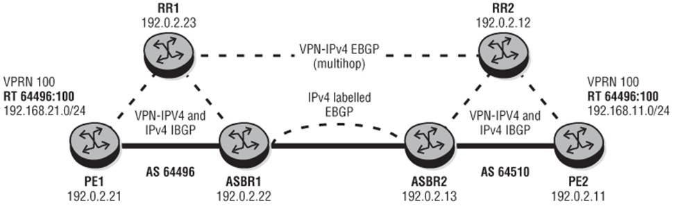
I'll use the topology depicted in Figure 5-4 to illustrate the use of Inter-AS Type C. Routers PE1, ASBR1, and RR1 belong to AS 64496, while Routers PE2, ASBR2, and RR2 belong to AS 64510. PE1 and ASBR1 in AS 64496 are IBGP peered with RR1; ASBR1 for the labeled IPv4 Address Family and PE1 for the labeled IPv4 and VPN-IPv4 Address Families. All three routers advertise their system addresses into labeled IPv4 BGP. Similarly, routers PE2 and ASBR2 in AS 64510 are IBGP peered with RR2; ASBR2 for the labeled IPv4 Address Family and PE2 for the labeled IPv4 and VPN-IPv4 Address Families. Again all three routers advertise their system address into labeled IPv4 BGP. Routers ASBR1 and ASBR2 peer in labeled IPv4 EBGP to advertise system addresses between AS 64496 and AS 64510. The Route-Reflectors RR1 and RR2 peer in multihop EBGP for the VPN-IPv4 Address Family, but do not modify the Next-Hop attribute of any advertised VPN prefixes.
Figure 5-4 Inter-AS Type C Topology
Output 5-9 illustrates the configuration implemented on ASBR1. ASBR1 is responsible for advertising labeled system addresses from AS 64496 toward the adjacent ASBR (ASBR2), setting Next-Hop to self, and programming a label swap action for the received/advertised BGP labels. ASBR1 is also responsible for redistributing labeled BGP prefixes learned from ASBR2 into IBGP toward RR1, again setting Next-Hop to self and again programming a label swap action for received/advertised BGP labels.
The configuration for external peering includes the advertise-inactive command, which, as described in the previous section, causes the best BGP route (and only the best route) to be advertised even if it is not the most preferred route within the system for a given destination (in this case the system addresses from AS 64496). The configuration includes the command advertise-label ipv4, which enables the use of labeled BGP for the IPv4 Address Family.
Output 5-9: ASBR1 BGP Inter-AS Type C Configuration
bgp
group "EBGP"
family ipv4
neighbor 192.168.0.50
peer-as 64510
advertise-inactive
advertise-label ipv4
exit
exit
group "IBGP"
family ipv4 vpn-ipv4
neighbor 192.0.2.23
peer-as 64496
advertise-label ipv4
exit
exit
no shutdown
As described previously, in its role as ASBR router, ASBR1 performs a label swap of BGP labels received in IBGP and advertised in EBGP. It does the same for labels received in EBGP and advertised in IBGP. In the former case, it is also necessary to push on a transport level label (for example, LDP or RSVP) to reach a non-adjacent next hop. The labels are programmed on a {Next-Hop, Received Label} basis and can be verified using the “show router bgp inter-as-label” command as shown in Output 5-10.
Output 5-10: ASBR1 Inter-AS BGP Label
A:PE2# show router bgp inter-as-label
=============================================================
BGP Inter-AS labels
=============================================================
NextHop Received Advertised Label
Label Label Origin
------------------------------------------------------------
192.0.2.21 131067 262138 Internal
192.0.2.22 0 262140 Edge
192.0.2.23 262143 262139 Internal
Output 5-11 illustrates the configuration requirements for the Route-Reflector RR1 in AS 64496. For the internal BGP peers, note again the use of the advertise-inactive and advertise-label ipv4 commands as well as the configuration of a cluster to define these peers as Route-Reflector clients. For the external peer, the session is configured for multihop with a TTL indicating up to 10 hops. It allows for policy to be applied on the peering session using the export command followed by a policy name, together with the vpn-apply-export command necessary to enforce base BGP instance policy on VPN-IPv4 prefixes.
Output 5-11: RR1 Inter-AS Type C Configuration
bgp
group "EBGP"
family vpn-ipv4
peer-as 64510
local-address 192.0.2.23
neighbor 192.0.2.12
multihop 10
vpn-apply-export
export "EBGP-VPN-IPv4"
exit
exit
group "CLIENTS"
family ipv4 vpn-ipv4
cluster 192.0.2.23
peer-as 64496
neighbor 192.0.2.21
advertise-inactive
advertise-label ipv4
exit
neighbor 192.0.2.22
advertise-inactive
advertise-label ipv4
exit
exit
no shutdown
The scenario where an SR-OS device is deployed as Route-Reflector for labeled IPv4 or IPv6 routes highlights an interesting problem. When the Route-Reflector receives a labeled prefix, it attempts to resolve the BGP Next-Hop (which will be an IPv4 address for a labeled-IPv4 prefix or an IPv4-mapped IPv6 address for a 6PE prefix) to an LSP as part of its decision process. In the event that the Route-Reflector is not running MPLS (which is a typical configuration for a control plane only Route-Reflector), any labeled prefixes in the RIB-IN are marked as “invalid.” In this case, the prefix is still reflected, but in the event that there are a number of paths in the RIB-IN, only the first “invalid” path received is advertised. The workaround is to enable MPLS control-plane on the Route-Reflector, in which case routes in the RIB-IN are considered “valid.” The problem will be resolved by introducing the capability to instruct BGP to use the IP route table for resolving the Next-Hop of labeled IPv4 prefixes rather than the tunnel-table at a control-plane-only Route-Reflector.
Using these configurations, the BGP labels are propagated across the Autonomous Systems and allow for Inter-AS LSPs to be established. These can be verified at PE1, where LSPs to RR1 and ASBR1 are established through LDP; but LSPs to ASBR2, PE2, and RR2 are established through BGP. As previously discussed, because the BGP-learned labels are from a non-adjacent peer (although ASBR1 is physically adjacent, the peering session is between system addresses, and not considered adjacent), PE1 must impose a transport level label onto the BGP label to reach the next hop. So we have a three-level label stack consisting of service label, BGP label, and, in this case, LDP label.
At a service level, no specific configuration is required to establish a Layer-3 VPN between the Autonomous Systems. VPRN 100 is configured on Routers PE1 and PE2 to provide Inter-AS connectivity, and PE2 advertises prefix 192.168.11.0/24 with Route-Target 64496:100, which is imported by PE1 as shown in Output 5-13. Note that the VPN-IPv4 prefix advertised by PE2 is received at PE1 with the Next-Hop still reflected as PE2 (192.0.2.11). To forward traffic in the data-path, PE1 must resolve that Next-Hop address to the BGP LSP for PE4 shown in Output 5-12.
PE-CE IPv6 for BGP/MPLS IP-VPNs (VPN-IPv6) in an Inter-AS environment is supported in SR-OS. The mechanics are largely the same as for VPN-IPv4, but in this case the system must resolve the IPv4-mapped IPv6 Next-Hop address to a BGP LSP.
Output 5-12: PE1 Tunnel-Table
A:PE1# show router tunnel-table
======================================================================
Tunnel Table (Router: Base)
======================================================================
Destination Owner Encap TunnelId Pref Nexthop Metric
----------------------------------------------------------------------
192.0.2.11/32 bgp MPLS - 10 192.0.2.22 1000
192.0.2.12/32 bgp MPLS - 10 192.0.2.22 1000
192.0.2.13/32 bgp MPLS - 10 192.0.2.22 1000
192.0.2.22/32 ldp MPLS - 9 192.168.0.130 100
192.0.2.23/32 ldp MPLS - 9 192.168.0.130 200
-----------------------------------------------------------------------
Flags: B = BGP backup route available
======================================================================
Output 5-13: Router PE1 VPRN 100 Route-Table
*A:PE1# show router 100 route-table
=======================================================================
Route Table (Service: 100)
=======================================================================
Dest Prefix[Flags] Type Proto Age Pref
Next Hop[Interface Name] Metric
-----------------------------------------------------------------------
192.168.11.0/24 Remote BGP VPN 00h03m08s 170
192.0.2.11 (tunneled) 0
192.168.21.0/24 Local Local 00h02m58s 0
loopback0 0
-----------------------------------------------------------------------
No. of Routes: 2
Flags: L = LFA nexthop available B = BGP backup route available
n = Number of times nexthop is repeated
=======================================================================
Carriers' Carrier
The BGP/MPLS IP-VPN framework (RFC 4364) defines a model where the VPN provided to a user may be a Service Provider that is in turn providing services to its own customer base. This provider may be an ISP, or it may be a provider that is also offering IP-VPN services. In either case, the provider uses the backbone of another Service Provider to extend its connectivity, and the method of delivery over this backbone is referred to as the Carriers' Carrier model or Carrier Supporting Carrier (CSC) model.
In this model, CE routers (CSC-CE) run MPLS toward the Carriers' Carrier PE routers (CSC-PE) and advertise infrastructure prefixes (system addresses) in labeled IPv4 BGP. These CSC-CE infrastructure prefixes are advertised by the CSC-PEs in VPN-IPv4 throughout the Carriers' Carrier network and subsequently redistributed to other CSC-CE sites using labeled IPv4 BGP. That is, for a given provider infrastructure prefix, the CSC-PE implements a label-swap between the received IPv4 BGP label and the advertised VPN-IPv4 label and vice-versa. The result is that a given CSC-CE should hold a route to every other CSC-CE participating in the VPN, together with a label distributed for that route.
Figure 5-5 Carriers' Carrier Architecture
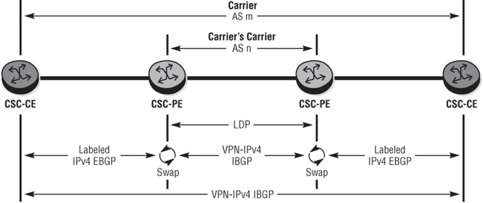
When a CSC-CE router needs to forward a packet to another CSC-CE router participating in the VPN, it imposes the label advertised by the neighboring CSC-PE for that infrastructure address. When it reaches the CSC-PE, it does not implement any kind of IP route lookup but rather uses the top label to determine the BGP Next-Hop and carries out a label swap. If the BGP Next-Hop is not adjacent, the CSC-PE also pushes on a transport level label using LDP or RSVP to reach that destination. When the packet arrives at the egress CSC-PE, the transport level label is removed (if it wasn't already removed by the penultimate hop router) and the received VPN-IPv4 label is swapped for the IPv4 BGP label advertised by the egress CSC-CE.
The notable difference between the Carriers' Carrier model and conventional IP-VPNs is that the CSC-PE must run MPLS toward the CSC-CE routers within the context of a VRF. This allows the CSC-CE routers participating in the VPN to build a mesh of LSPs to every advertised infrastructure address. When this LSP mesh exists, the CSC-CEs can establish their own BGP peering sessions for the advertisement of NLRI. In the case of a provider offering its own VPN services, CSC-CEs advertise VPN-IPv4 prefixes, which are totally transparent to the Carriers' Carrier CSC-PE routers. In the case of an ISP, IPv4 prefixes are advertised between CSC-CEs, but again they are totally transparent to the CSC-PEs.
The schematic in Figure 5-6 illustrates the use of the Carriers' Carrier model to provide hierarchical IP-VPNs. In this simple topology, CSC-PE1 and CSC-PE2 form the Carriers' Carrier backbone AS 64496 and use VPRN 100 to provide a Carriers' Carrier VPN. CSC-CE1 and CSC-CE2 are simulating provider PE routers, in turn providing a VPN service to their own customer base using VPRN 500. Note that while this simple topology shows provider VPNs being delivered directly from the CSC-CEs, it is entirely possible that provider PEs can be attached “behind” the CSC-CEs to deliver services. In this case, however, it would be necessary for the CSC-CEs to redistribute infrastructure prefixes and labels learned in IPv4 EBGP into IBGP (with label) or an IGP with LDP.
Figure 5-6 Carriers' Carrier Topology
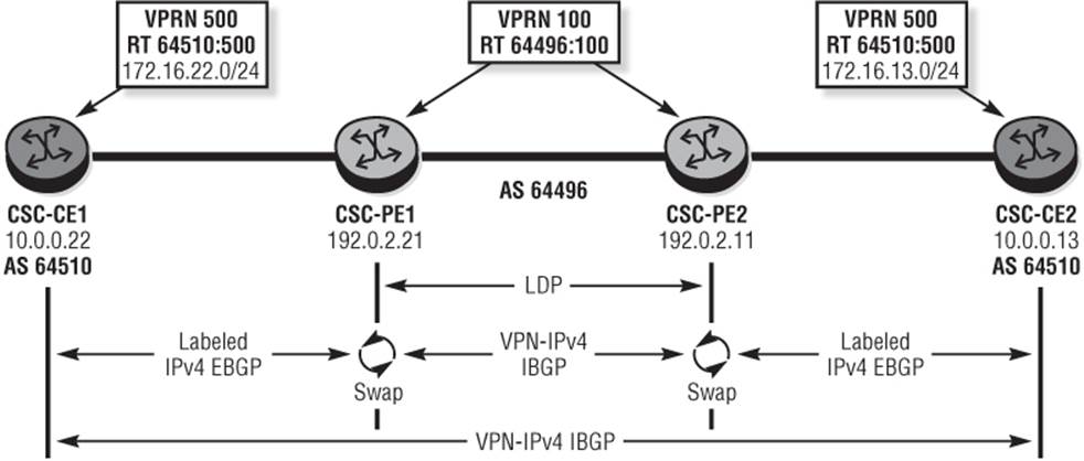
Output 5-14 illustrates the configuration requirements for CSC-PE1 in order to support Carriers' Carrier VPN. The difference between a conventional VPN and a Carriers' Carrier VPN is the addition of the carrier-carrier-vpn command, which essentially enables the use of MPLS within the context of a VPRN. In addition, unlike a conventional PE-CE interface defined as an access interface, the interface toward CSC-CE1 is defined as a network-interface, again to support MPLS. The BGP peering toward CSC-CE1 includes the command advertise-label ipv4, enabling the use of labeled BGP for the IPv4 Address Family, while the associated export policy simply exports all prefixes from protocol BGP-VPN to protocol BGP. Lastly, because both CSC-CEs are in a common AS, the CSC-PE routers use the as-override command to replace AS 64510 in the AS_PATH attribute with the backbone AS number 64496 when advertising IPv4 prefixes to the CSC-CEs. This allows for the use of a common AS number across CSC-CEs while ensuring that IPv4 infrastructure addresses advertised by CSC-PEs are not rejected because of their own AS number appearing in the AS_PATH attribute.
Output 5-14: CSC-PE1 Configuration
vprn 100 customer 1 create
carrier-carrier-vpn
autonomous-system 64496
route-distinguisher 64496:100
auto-bind ldp
vrf-target export target:64496:100 import target:64496:100
network-interface "to-CSC-PE1" create
address 192.168.0.1/30
port 1/1/2:100
no shutdown
exit
bgp
group "EBGP"
family ipv4
peer-as 64510
neighbor 192.168.0.2
as-override
export "VRF100-EBGP"
advertise-label ipv4
exit
exit
no shutdown
exit
no shutdown
At CSC-PE1 you can verify that a label swap entry exists for CSC-CE1. Note that the show router bgp inter-as-label output shown in Output 5-15 only shows entries on a {next-hop, received-label} basis. The output shows the received label 262141 for IPv4 prefix 10.0.0.22/32 (system address of CSC-CE1) and the associated label 262138 advertised into VPN-IPv4, but does not show the corresponding label swap entry for CSC-CE2's system address, which was learned through VPN-IPv4 from CSC-PE2 and advertised in labeled IPv4 BGP toward CSC-CE1. This is seen using the command show router 100 bgp inter-as-label as shown in Output 5-16.
Output 5-15: CSC-PE1 BGP inter-as-label output
*A:CSC-PE1# show router bgp inter-as-label
===============================================================
BGP Inter-AS labels
===============================================================
NextHop Received Advertised Label
Label Label Origin
---------------------------------------------------------------
192.168.0.2 262141 262138 ExtCarCarVpn
---------------------------------------------------------------
Total Labels allocated: 1
===============================================================
Output 5-16: CSC-PE1 BGP inter-as-label output for VPRN 100
*A:CSC-PE1# show router 100 bgp inter-as-label
===============================================================
BGP Inter-AS labels
===============================================================
NextHop Received Advertised Label
Label Label Origin
---------------------------------------------------------------
192.168.0.2 262141 131067 External
192.0.2.11 262136 131064 Internal
---------------------------------------------------------------
Total Labels allocated: 2
===============================================================
In SR-OS, the default mode of label allocation is label-per-VRF. For a Carrier Supporting Carrier VPRN, labels are allocated on a {next-hop, received label} basis, which is essentially what BGP always does when implementing label swaps. A per-VRF label does not provide sufficient context simply because different prefixes may be forwarded over the same or different PE-CE links with the same or different MPLS labels. In essence, a per-VRF label works only when the VRF does an IP lookup.
At CSC-CE1 you can also verify the presence of a BGP-signaled LSP to CSC-CE2 (10.0.0.13) with a Next-Hop of CSC-PE1 (192.168.0.1).
Output 5-17: CSC-CE1 Tunnel Table
*A:CSC-CE1# show router tunnel-table
===============================================================
Tunnel Table (Router: Base)
===============================================================
Destination Owner Encap TunnelId Pref Nexthop Metric
---------------------------------------------------------------
10.0.0.13/32 bgp MPLS - 10 192.168.0.1 1000
---------------------------------------------------------------
Flags: B = BGP backup route available
===============================================================
With IP/MPLS connectivity in place between CSC-CE1 and CSC-CE2, an IBGP session for the VPN-IPv4 Address Family is extended between the two and a single VPRN provisioned on both CSC-CEs with parameters outlined in Output 5-18. Note the presence of the auto-bind mplsparameter, which enables BGP Next-Hops to be resolved to any LSP that is present, including BGP LSPs. This represents a two-level label stack between CSC-CE and CSC-PE (service label, BGP label), and a three-level label stack between CSC-PEs (service label, VPN-IPV4 label, LDP label).
Output 5-18: CSC-CE1 VPRN 500 Configuration
service
vprn 500 customer 1 create
route-distinguisher 64510:500
auto-bind mpls
vrf-target export target:64510:500 import target:64510:500
interface "loopback" create
address 172.16.22.1/24
loopback
exit
no shutdown
exit
exit
Output 5-19: CSC-CE1 VPRN 500 Route-Table
*A:CSC-CE1# show router 500 route-table
=======================================================================
Route Table (Service: 500)
=======================================================================
Dest Prefix[Flags] Type Proto Age Pref
Next Hop[Interface Name] Metric
-----------------------------------------------------------------------
172.16.13.0/24 Remote BGP VPN 20h30m03s 170
10.0.0.13 (tunneled) 0
172.16.22.0/24 Local Local 20h30m06s 0
loopback 0
-----------------------------------------------------------------------
No. of Routes: 2
Flags: L = LFA nexthop available B = BGP backup route available
n = Number of times nexthop is repeated
=======================================================================
Finally, you can verify that VPN-IPv4 prefixes are correctly exchanged between the CSC-CEs. At CSC-CE1, observe that the VPN-IPv4 prefix 172.16.13.0/24 is populated into the VRF with a Next-Hop of 10.0.0.13 equating to CSC-CE2. As previously described, these VPN-IPv4 prefixes are exchanged just between the CSC-CEs and are transparent to the CSC-PE routers.
Notes
1. The specification also allows for redistribution of labeled IPv4 prefixes from EBGP into some other label distribution protocol (LDP), although this model has not been widely adopted.
2. The ingress and egress PEs cannot be in the same Autonomous System, and can be separated by one or more intermediate Autonomous Systems.
All materials on the site are licensed Creative Commons Attribution-Sharealike 3.0 Unported CC BY-SA 3.0 & GNU Free Documentation License (GFDL)
If you are the copyright holder of any material contained on our site and intend to remove it, please contact our site administrator for approval.
© 2016-2026 All site design rights belong to S.Y.A.