Make: More Electronics (2014)
Chapter 10. Experiment 10: From Sound to Light
You can now create a noise-activated LED. Figure 10-1 shows the same circuit as before, with just five components added. A photograph is included in Figure 10-2.
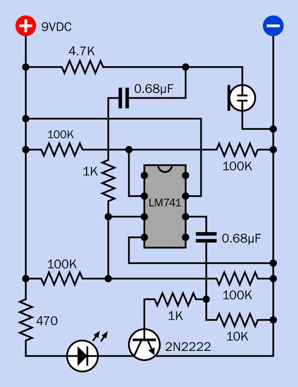
Figure 10-1. This op-amp test circuit will flash the LED whenever the electret microphone picks up sound of moderate intensity.
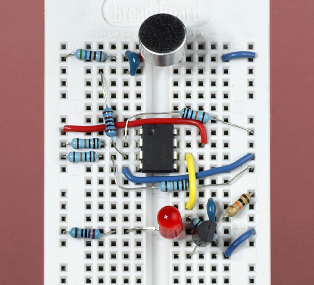
Figure 10-2. The circuit with a noise-activated LED, breadboarded (9V battery is not shown).
An LED-Transistor Combination
After the output from the LM741 passes through the coupling capacitor, it reaches the midpoint between a 1K resistor and a 10K resistor. Consequently, voltage fluctuations created by the op-amp are now relative to ground. They pass through the 1K resistor to the base of that plain-and-simple workhorse, a 2N2222 transistor. The transistor responds by amplifying current through an LED.
The circuit now flashes the LED in sync with your voice when you talk into the microphone. For some reason I find this magical. Maybe I’m just easy to please! If you don’t share my sense of wonder about such simple things, rest assured we have only just started on a mission toward a much more ambitious circuit.
If the circuit doesn’t perform exactly as I just described, here is a list of possible issues:
The LED won’t light up
This is almost certainly the result of a wiring error. Check everything slowly and carefully, and apply your meter to each stage of the circuit, remembering to test for AC as well as DC.
The LED stays on all the time
This is unlikely to happen, but variations in components can have unexpected results. The particular 2N2222 transistor that you use, and the particular LED, may affect the behavior of the circuit slightly. If your LED suffers from the always-on problem, most likely the voltage at the base of the transistor is just high enough, even without a signal from the op-amp, to enable some current to pass from the collector to the emitter. Substitute a higher-value resistor instead of the 1K resistor at the base, and this problem should be resolved.
The LED flashes rhythmically
This kind of oscillation can be a problem in op-amp circuits. When the LED is bright, it draws a little more current, which can pull down the voltage from a 9V battery. This affects the voltages in the voltage dividers. A lower voltage difference causes the LED to dim, at which point it draws less current from the battery—and the cycle repeats. This is most likely to occur when you make a relatively low noise into the microphone. It’s less likely to occur if you power the circuit with an AC adapter that has a more stable DC output than a battery.
Before we move on, there’s one other thing for you to try. Remove the LED and substitute a very small loudspeaker. Hold the loudspeaker up to your ear. Now when you speak into the microphone, you should just be able to hear a faint, really horrible scratchy version of your voice—although it is likely to suffer from the same kind of oscillation that I described above.
You may need a loudspeaker with a relatively high impedance to make this work. I got results with a 2” 63Ω speaker. If you try to make it louder by reducing the value of the 470Ω resistor, you’ll probably find that the sound from the speaker becomes even more distorted. Why does it sound so bad? To fix it, we’re going to need the negative feedback that I mentioned earlier.
All materials on the site are licensed Creative Commons Attribution-Sharealike 3.0 Unported CC BY-SA 3.0 & GNU Free Documentation License (GFDL)
If you are the copyright holder of any material contained on our site and intend to remove it, please contact our site administrator for approval.
© 2016-2026 All site design rights belong to S.Y.A.