Make: More Electronics (2014)
Chapter 12. Experiment 12: A Functional Amplifier
As you saw in Experiment 10, an LM741 is not appropriate to drive a loudspeaker, even through a 2N2222 transistor. Really the LM741 is intended to be a bare-bones preamplifier, which increases the voltage from a very small input signal but cannot deliver significant power. A preamplifier is often referred to as a “preamp.”
Fully-featured preamplifiers used to be available in the consumer-electronics world as standalone devices, to amplify inputs from a tape deck, a microphone, or a phonograph cartridge. They included some adjustments for volume, bass, and treble, and then passed the signal along to a power amplifier, which was designed to drive loudspeakers. Today a preamplifier and a power amplifier are usually combined in one unit, as in a typical stereo receiver or home entertainment system. For our purposes, though, the LM741 is the equivalent of a preamp, and we now need a power amplifier.
This can be another bare-bones device, the LM386 chip. It has the same dual-input format as an op-amp but is designed to drive a small loudspeaker with about 300mW of power. That sounds puny compared with the wattage that you can expect from a modern music system, but in fact, 300mW is enough for many practical purposes.
Introducing the 386 Chip
The pinouts of the LM386 are shown in Figure 12-1. It’s similar to the LM741, but not exactly the same, so be careful when you attach the power supply and the output.
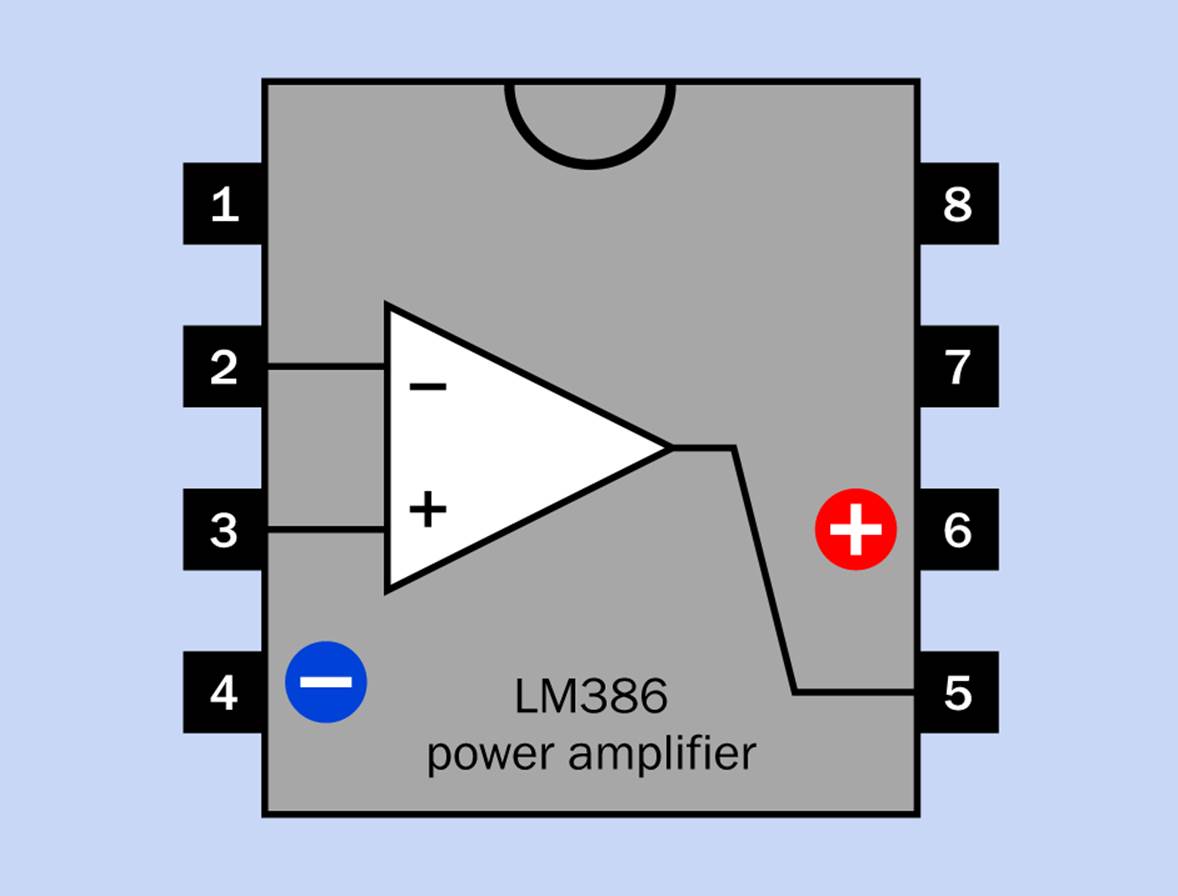
Figure 12-1. The interior workings of an LM386 amplifier chip. Pins 1 and 8 are reserved for an external capacitor that can increase the gain of the chip from its default gain of 20:1 all the way up to 200:1.
Pins 1, 7, and 8 are shown with no connections. They can be used in conjunction with external components if you wish to increase the gain of the amplifier from 20:1 (its default value) all the way up to 200:1. This is liable to create a lot of distortion, but if you want to try it, add a 10µF capacitor between pins 1 and 8, and put a 0.1µF capacitor between pin 7 and ground. This configuration has the advantage of diminishing the tendency of the LM386 to go into oscillations or create noise. If 200:1 is too high an amplification ratio, put a resistor of 1K or higher in series with the 10µF capacitor between pins 1 and 8.
The Amplification Circuit
If you look now at the schematic in Figure 12-2, several aspects of it should appear familiar. You’ve seen the simple microphone section before. Its output modifies the middle voltage created by the two 68K resistors functioning as a voltage divider. The voltage fluctuations are then connected with the noninverting input of the LM741.
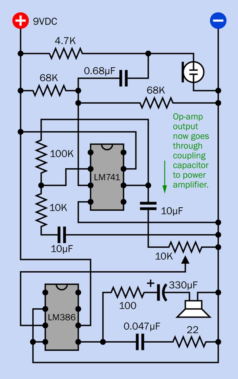
Figure 12-2. A complete audio amplifier with microphone and loudspeaker. The LM741 forms the preamplifier stage, while the LM386 is the power amplifier.
Feedback from pin 6 of the LM741 circles around through the 100K feedback resistor to the inverting input, and is modified by the 10K “ground” resistor. The 10µF capacitor between this resistor and the negative bus allows the inverting input of the LM741 to “float” independent of the power supply so that a voltage divider is not needed in this input. (If these terms don’t entirely make sense to you, I have to ask you to go back and re-read the previous technical stuff beginning in Experiment 11—assuming you want to know what they mean.)
The output from the LM741 passes through a 10µF coupling capacitor to a 10K trimmer potentiometer, which functions as a volume control for the LM386. The wiper from this potentiometer is connected with pin 3 of the LM386, which is its noninverting input. Pin 2, its inverting input, is connected with negative ground. The LM386 amplifies the variations between its two inputs, just like the LM741, except that its output is just powerful enough to drive a small loudspeaker. Note the substantial 330µF capacitor and the 100Ω resistor in series with the loudspeaker.
This circuit will demonstrate the tradeoff between gain and distortion. If you substitute a lower value for the 100Ω resistor, your voice will sound louder, but more distorted. You can experiment with the value of this resistor, and with different loudspeakers, as well as the trimmer that adjusts the gain.
A breadboarded version of Figure 12-2 is shown in Figure 12-3.
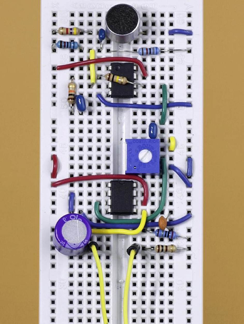
Figure 12-3. A breadboarded version of the simple circuit using an LM386 amplifier. Yellow wires at the bottom of the picture are connected with a loudspeaker, not shown. The circuit can run for a limited time from a 9V battery.
Troubleshooting the Amplifier
Here are a few ways to troubleshoot the amplifier:
Noise
If you hear whistles, buzzing, or rhythmic oscillations when you power up the circuit, this can be the result of various factors:
§ Bad wiring. If you use jumper wires with plugs at each end, the tangle that they create is almost guaranteed to pick up electrical noise. This circuit should be wired with jumpers cut to size and placed flat against the breadboard. Components should be spaced as closely as possible.
§ Acoustic feedback. Try moving the speaker farther away from the microphone.
§ Add the components to pins 1, 7, and 8 of the LM386, as I described previously. Grounding pin 7 of the LM386 through a 0.1µF capacitor can suppress noise if you do this in conjunction with the capacitor and optional series resistor linking pins 1 and 8.
§ Increase the 0.047µF capacitor to 0.1µF.
§ If you are using a benchtop power supply instead of a battery, this may add some humming or buzzing through the speaker. Add the highest value capacitor you can find between the positive and negative buses of the circuit board. Although I have a fairly high-qualify power supply myself, I still found that a 4,700µF capacitor reduced some background hum.
Distortion
Because this is such a basic little circuit, some distortion is inevitable. You can try these options:
§ Substitute a 3.3K resistor for the 4.7K resistor in series with the electret microphone.
§ Insert a 10K resistor in series between the wiper of the 10K trimmer potentiometer and the input of the LM386 on pin 3.
Insufficient sound
You won’t get much volume from this little circuit, but here are a couple of options to try:
§ The combination of resistors with the LM741 creates a gain of 1 + (100/10) = 11:1 in the preamp stage. Try substituting a 150K resistor for the 100K resistor, to increase the gain to 16:1. You can also reduce the value of the 10K “grounding” resistor.
§ You can increase the perceived loudness by placing the loudspeaker in a small closed box or tube. I find that 6” length of 2” diameter PVC water pipe works well as an enclosure for a 2” speaker.
§ I got good results by connecting the output from the LM386, and a ground wire, to the input plug of a computer speaker system (which contains its own little amplifier). Try this at your own risk! The 330µF capacitor should protect your speaker system, but if you make a wiring error, the results will be unpredictable.
All materials on the site are licensed Creative Commons Attribution-Sharealike 3.0 Unported CC BY-SA 3.0 & GNU Free Documentation License (GFDL)
If you are the copyright holder of any material contained on our site and intend to remove it, please contact our site administrator for approval.
© 2016-2026 All site design rights belong to S.Y.A.