Make: More Electronics (2014)
Chapter 14. Experiment 14: A Successful Protest
First I will restate the problem. Using the original concept of the Noise Protest Device that I developed in the previous experiment, if someone shouts loudly, the Protest Output will start and never stop. How can I deal with this?
One solution would be an audio filter on the microphone input so that the Noise Protest Device can’t hear its own noise but still hears when someone shouts. This would be possible, but I’m not confident that it would work reliably.
Another solution would be simply to limit the duration of the Protest Output to, say, a couple of seconds. Then there’s a pause while the Protest Output is suppressed. At the end of the pause, the Protest Output is now silent so it cannot retrigger the circuit, and if there’s no more shouting, the device has done its job and can keep quiet. If someone is still shouting, however, the cycle will repeat.
This is more complicated than the original specification, but that’s what usually happens after you build a prototype. Even when it works well, you find that it lacks some desirable features, and you have to build a second version. In every book I have ever written and every gadget that I have ever built, after the initial version has been delivered to the client, the client will want something more, or I will.
Timing Is Everything
How can I set a time limit on the Protest Output? By using a timer, of course! It will be in one-shot mode. And then how can I follow this with a pause? Well, how about if the first timer triggers a second timer, when the first timer reaches the end of its cycle? This is doable. In Make: Electronics, I showed how one timer can trigger another.
I’d better give my new pair of timers names to tell them apart. I’ll call them the Noise Duration Timer and the Pause Duration Timer.
The Noise Duration Timer will be triggered by the op-amp. Wait a minute—that was where all my problems began, in the previous version. Yes, but the trigger pin on a 555 timer behaves quite differently from the reset pin. First, if the supply voltage is 9VDC, the trigger only requires a voltage below 3VDC, whereas the reset pin requires a voltage below 1VDC. And second, if there are any fluctuations in the voltage after the timer has been triggered, it ignores them until the end of its cycle.
You see why it’s important to read datasheets to learn these details. Anyway, I believe that I can make the trigger pin compatible with the output from the LM741.
The output pin of the Noise Duration Timer will send power to an off-the-shelf noise maker, such as a beeper—or maybe a burglar alarm siren, which would really get people’s attention. A beeper will cost maybe a couple of dollars, while a siren will be closer to $10. Either will work from a 9V supply.
When the Noise Duration Timer reaches the end of its period, its output will go low, which will shut down the external noise-making device. It will also pass through a coupling capacitor to the Pause Duration Timer, and the sudden drop in voltage will trigger it. Now while the Pause Duration Timer is going through its cycle, it must somehow inhibit the circuit from starting up again.
Maybe I can use the output from the Pause Duration Timer to pull down the reset pin of the Noise Duration Timer. What, we’re back to using the reset pin again? Yes, but the output from the Pause Duration Timer will be DC, without any ripples in it, and it should be more robust than the output from an op-amp passing through a transistor. I think it will work.
At the end of the pause, the Pause Duration Timer releases the Noise Duration Timer, so that if there is still someone shouting, the process will repeat.
The final version of the circuit is in Figure 14-1. I have also updated the flow diagram from Figure 13-9 to show the new logic. The revised version is in Figure 14-2.
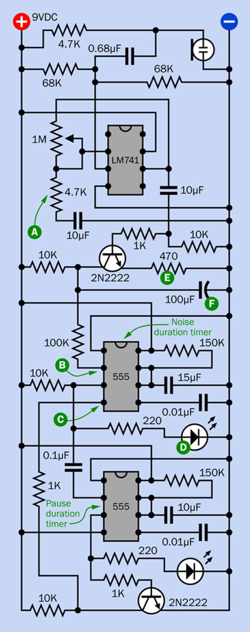
Figure 14-1. The corrected version of the Noise Protest Device, to rectify flaws in the original version.
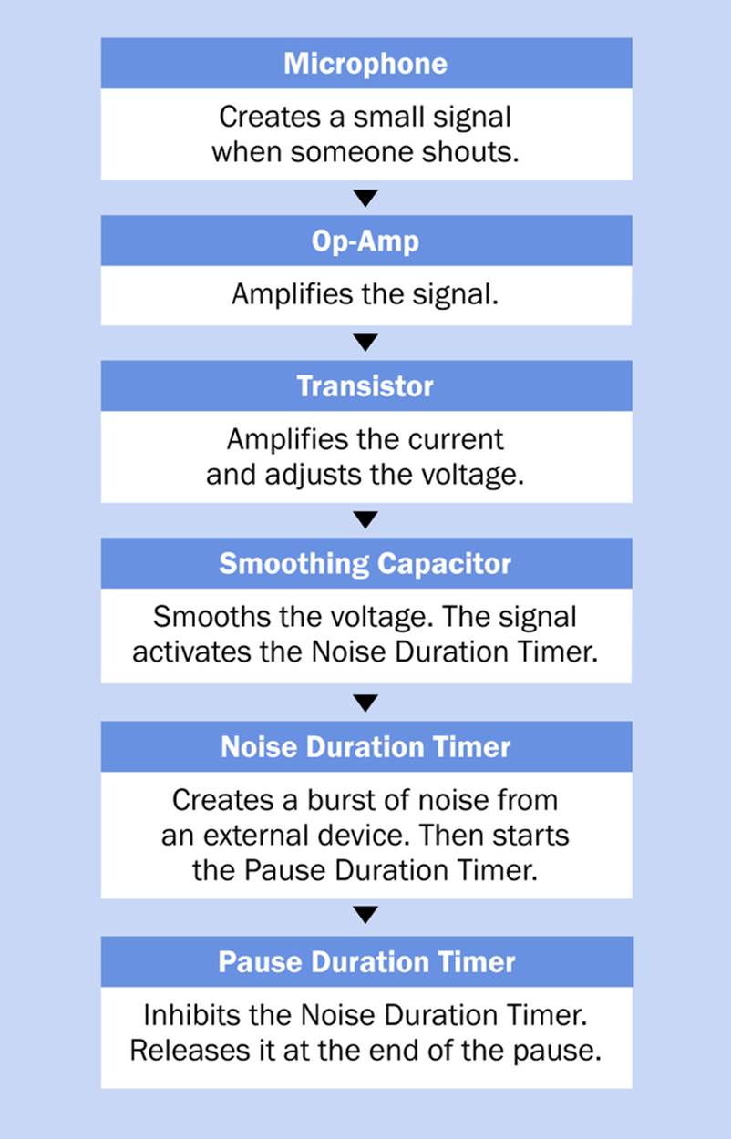
Figure 14-2. A flowchart illustrating the logic of the final version of the Noise Protest Device.
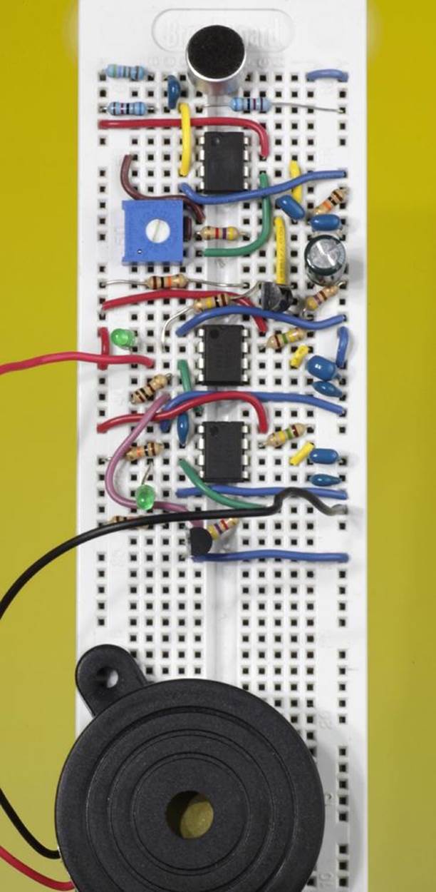
Figure 14-3. The final Noise Protest Device. The large round object is a heavy-duty beeper. The circuit will run for a limited time from a 9V battery.
Revision Summary
One important change that I had to make: the “grounding” resistor, which adjusts negative feedback to the LM741, has been changed from 10K to 4.7K. I’ve identified it in the new schematic with a green “A.” The reason for this change is to increase the amplification of the op-amp to make it more sensitive. If it’s too sensitive, you can just dial back the 1M trimmer.
The original 2N2222 transistor has been rewired, so that instead of inhibiting a 555 timer, it now triggers the Noise Duration Timer with a low signal. Remember, the voltage only has to go below 3VDC (one-third of the supply voltage). Apply your meter to the location marked “B” and you’ll see it responding when you shout into the microphone.
The output from the Noise Duration Timer goes to an LED, just for demonstration purposes. I labelled this LED with a “D” in the schematic. If you want the circuit to perform usefully, you’ll swap out the LED and substitute a beeper. If you want more noise, you may need a relay to trigger a more powerful external device. An optocoupler would be best, as it will completely isolate the device from the sensitive circuit containing the LM741. However, a very small electromechanical relay should work.
While the Noise Duration Timer is running, its output is high. At the end of its cycle, the output goes low. This transition passes through the 0.1µF coupling capacitor, momentarily overwhelms a 10K pullup resistor, and triggers the Pause Duration Timer. The output from this timer goes to a transistor at the bottom of the schematic, which converts it to a low output to inhibit the Noise Duration Timer by pulling its reset pin low. You can check at point “C” that this voltage is now in the correct range. The LED on the output from the Pause Duration Timer is just included so that you can see that it’s working; it can be omitted from the final version of the circuit.
When you have finished wiring the circuit, apply power. The initial power surge may activate one timer or the other. You can ignore that.
To check that the timers are working, briefly ground pin 2 (the trigger pin) of each of them. This should make the LED light up in each case. You can also use your meter to verify the input voltage on the trigger pin of the first timer. When you make a loud noise into the microphone, you should see the voltage dip.
The Noise Test
Now do your “Aaah” test and sustain the sound for as long as you can. There may be an initial hesitation. Then you should see the first LED light up for approximately two seconds. Imagine that its output is activating the external noise-making device. Then that LED goes out, and the second one comes on, to tell you that the Pause Duration Timer is inhibiting the Noise Duration Timer. You can continue making as much noise as you like, but the Noise Duration Timer will be prevented from responding, and its LED will stay dark, until the Pause Duration Timer has completed its cycle.
If you hold the meter probe on point “B” you may still see some small oscillations in the voltage, but they don’t matter anymore, because this circuit allows a bigger margin for error.
My copy of the Noise Protest Device works well, and I think your copy will work for you, too. However I have a few notes about the way in which it works.
The 100µF electrolytic capacitor (labelled “F” in the schematic) is necessary to smooth the AC signal that passes from the op-amp and through the transistor. However, this capacitor does take a second or so to charge. While it is charging, the Noise Duration Timer won’t respond. This simply means that there is a short delay from the moment when someone starts shouting to the moment when the Protest Response begins. Similarly, when someone stops making noise, the capacitor takes a second to discharge, so you may get one additional Protest Response cycle.
Personally I like this behavior, because the circuit gives the shouting person a brief grace period in which to behave, but once the circuit decides that he’s going to keep on shouting, it adds an extra cycle just to make sure that he’s got the message.
If you prefer a more immediate response, you can substitute a 47µF electrolytic smoothing capacitor. This may cause the Noise Duration Timer to retrigger itself spontaneously, because the smaller smoothing capacitor is allowing more voltage spikes to get through. You can stop the retriggering by backing off the 1M potentiometer a bit. This should still allow a reasonably sensitive response.
Some marginal differences remain between the behavior of this circuit with a benchtop power supply and with a 9V battery. The battery takes longer to charge the 100µF capacitor, and the circuit may seem a little less sensitive. If the 1M trimmer doesn’t provide you with enough range, you can always increase the sensitivity by reducing the value of the 4.7K resistor labelled “A” in the schematic.
I have tuned the circuit to be run from an AC adapter because it draws too much power to be used with a 9V battery for more than demo purposes.
I used the plastic-packaged version of the 2N2222 transistors. If you use the metal-can version, they have slightly more amplifying power, and you may have to adjust the 470Ω resistor labelled “E” in the schematic.
I didn’t have any problems with oscillation, but if you do, try increasing the value of the 100µF capacitor labelled “F.”
Make Even More
While I was working on this project, I started thinking of other things it could do. I have a friend who has two children who turn the family TV up loud. Instead of shouting to them to “Turn that thing down!” he can simply install a Noise Protest Device to do the job for him.
Alternatively you could use it as a car alarm, if you tape it securely to the inside of a window. Any sudden vibration should trigger the electret microphone.
If you have neighbors with a noisy barking dog, you could use the output from the Noise Protest Device to retaliate by triggering an ultrasonic transducer.
A friend of mine remarked that she could use the Noise Protest Device on herself, to remind her not to shout at her business partner when she gets frustrated because a work project isn’t progressing quickly enough.
Personally, though, I like the original purpose of the Noise Protest Device. I like to think of electronics pioneer Bob Widlar installing something like this in his office, so that when he really irritated someone (which seems to have happened fairly often), and they came in to yell at him, all he had to do was sit back and wait for the decibels to reach the critical level, at which point his version of the Noise Protest Device would kick in.
Probably, that would have annoyed his visitor even more.
Can You Do It with a Microcontroller?
The analog-digital converter in a typical microcontroller expects a range of voltages that is large compared with the millivoltages from a microphone. So, I think you’d still want to pass the microphone output through an op-amp and connect the output from the op-amp to the microcontroller. In fact, you can buy an electret soldered to a small board with a surface-mount amplifier on it.
Alternatively, some microcontrollers have programmable gain built in. But you will still be dealing with an AC waveform, and you’d have to sample it very rapidly to determine its amplitude. Really it would be easier for the microcontroller to process a rectified or smoothed version of the signal. That would require using a transistor and capacitor, because the output from the op-amp doesn’t have enough current for easy rectification.
So, you would have to use a lot of the same components that I put into the existing circuit.
After that, your task would be very simple, because it’s easy to program a microcontroller to do something in response to an input. Creating a noise output, then pausing, and then waiting for another input would be easy. In fact, you could add more features.
For instance, you could write code that counts how many times someone shouts within a short period—and the more often they shout, the more frequenty the microcontroller will tell a noisemaking device to make noise. Alternatively, with some additional components, the microcontroller could make the Protest Output gradually louder each time it is triggered.
I’m sure you could invent similar options. The bottom line, though, is that regardless of whether you use a microcontroller, you still need to know how to use an op-amp.
What’s Next?
Op-amps have many more uses, but many of the applications involve some fairly difficult concepts. I’ll leave it to you to read up on this subject if it interests you. (One book that I like is Make: Analog Synthesizers.)
I’m going to move on, now, to digital chips. I prefer digital components in many ways. They talk to each other without any worries about incompatible voltages, and they don’t overreact and amplify every tiny little ripple or glitch. Within reasonable limits, their inputs and outputs are either high or low. You can think of them as being on or off, or (in binary code) 1 or 0.
Bob Widlar had no interest in digital chips and the binary code that they use. Supposedly he once said, “Every idiot can count to 1.” Some of us, though, aren’t quite as smart as Bob was, and for us, digital circuits provide a welcome relief from the quixotic behavior of circuits in which everything fluctuates on an unpredictable basis.
All materials on the site are licensed Creative Commons Attribution-Sharealike 3.0 Unported CC BY-SA 3.0 & GNU Free Documentation License (GFDL)
If you are the copyright holder of any material contained on our site and intend to remove it, please contact our site administrator for approval.
© 2016-2026 All site design rights belong to S.Y.A.