Make: More Electronics (2014)
Chapter 18. Experiment 18: Time to Switch
Figure 18-1 introduces a new concept. It shows how each logic gate can be emulated by a pair of plain, ordinary switches, and each switch can be considered as an input to the gate.
When a switch is pressed, it’s the same as a logic input being high. When it is not pressed, this is the same as a logic input being low. Thus, in the illustration, the top pair of switches gives a high output only if the left switch AND the right switch are both pressed. Just like an AND gate!
Although—not quite. An AND gate output is either high or low. When the switches are open in Figure 18-1, the output is an open circuit. It will be floating, with no defined voltage. We need to add a pulldown resistor to control the state of each floating output. I omitted the resistors for simplicity.
There is another, more important difference between a logic gate and a pair of switches: the switches will conduct electricity in either direction, while the logic gate will not. You cannot feed current into the output of a logic gate and have it emerge from the input. This difference can create new headaches—although in some ways, it can also make things simpler.
Background: An XNOR Made from Light Switches
Just a brief digression—did you know that your home is very likely to have an XNOR gate in the wiring for its lighting? Typically this occurs where there is a flight of stairs. You have a switch at the top of the stairs, and another switch at the bottom. When the light is on, either of the switches will turn it off. When the light is off, either of the switches will turn it on.
Check the switch logic for XNOR in Figure 18-1. Imagine how the power flows for each combination of switches—and how it will flow if the position of either switch is changed.

Figure 18-1. Each of the switches emulates an input to a logic gate if pressure on the switch is seen as being equivalent to a high input. To avoid the output floating when switches are open, a pulldown resistor can be added.
Can you imagine a logic circuit that would provide the same functionality for three switches? That is, any of the switches must always reverse the state of a single light bulb. I’ll give you a hint: the center switch must have two poles.
Back to the Rock
Take a look at Figure 18-2 and compare it with Figure 17-1. They both have the same function, but the new version needs no logic gates. Each pair of switches that will create a win for Player A is wired in series, which is the same thing as ANDing them. All three pairs are tied together, which is the same thing as ORing them.
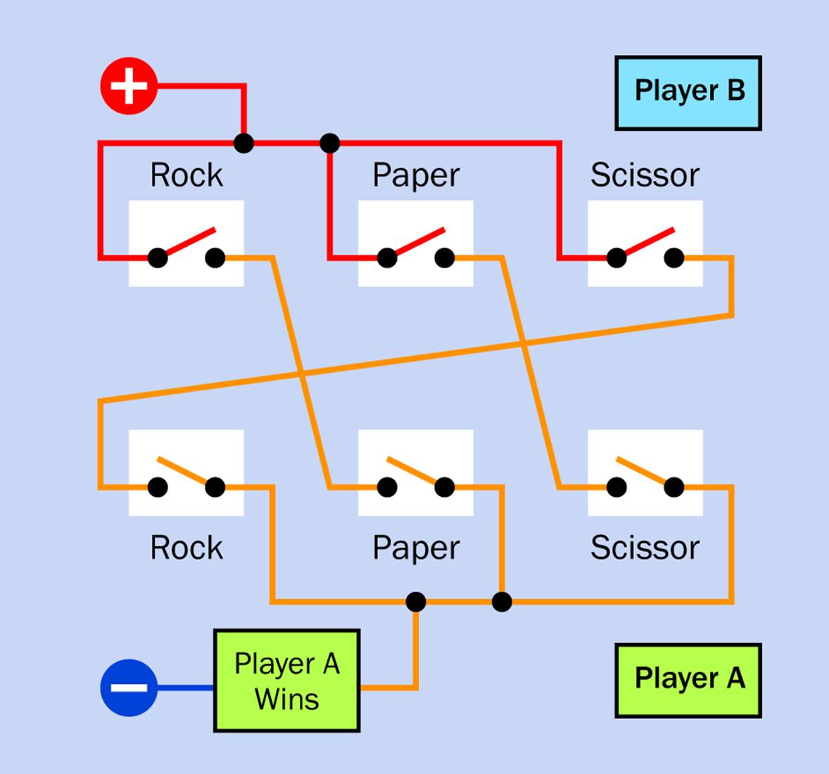
Figure 18-2. Using only switches, a circuit can produce a “Win” output for any of the three combinations favoring Player A in a Rock, Paper, Scissors game. The wire colors are included to provide clarity and can be seen as being like colored insulation.
If you’re wondering why I am showing switches in the schematic now, instead of pushbuttons, it’s because this circuit is going to end up with multiple-pole, double-throw switches; and although multiple-pole, double-throw pushbuttons do exist, they are more difficult to represent in schematics and take up more space. Just imagine that the switches are spring-loaded to return to their open state when they are not being pressed.
The conductors in Figure 18-2 are colored just for clarity because more are going to be added in the next few steps. Think of the colors as being like colored insulation on hookup wire.
Now if you look at Figure 18-3, you see the switch-and-wiring logic that responds if Player B wins. Can we combine the two circuits? We can’t connect the output from one switch to multiple other switches, in the way we connected the output from one switch to multiple logic gates. The hardwired connections will allow electricity to circle around and flow back, causing erroneous results. We have to use multiple-pole switches to keep each circuit separate, as shown in Figure 18-4.
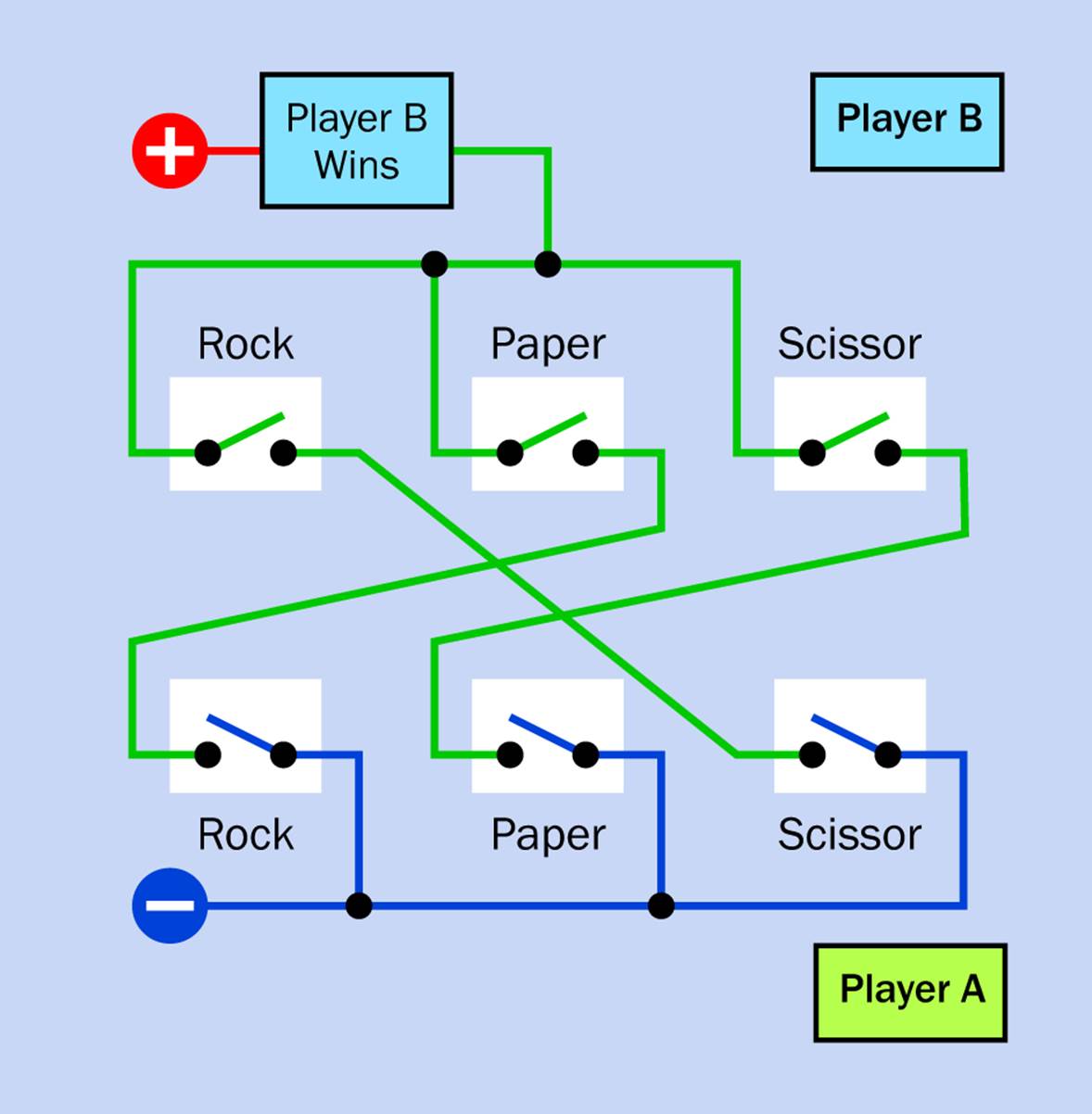
Figure 18-3. A switched circuit that produces a “Win” output for any of the combinations favoring Player B in a Rock, Paper, Scissors game.
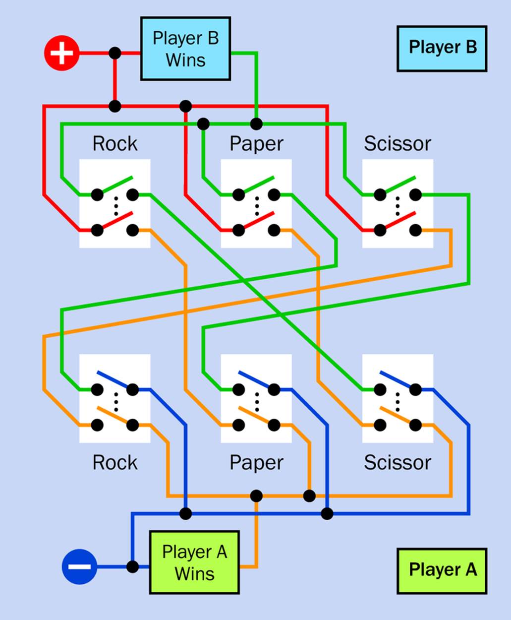
Figure 18-4. When the two previous schematics are combined, double-pole switches must be used to keep the two circuits electrically separate.
This circuit requires two-pole switches, but as I add extra features, still more poles will be required. Fortunately, pushbutton switches and push-twice switches (which use one push for “on” and a second push for “off”) are available with two, four, six, and even eight poles. (They are often used in relatively cheap stereo equipment.)
Showing Which Button
In Experiment 17, I complained that trying to do everything with logic gates was giving me a headache. This was just after I showed you a logic diagram in Figure 17-3 that would illuminate an LED beside a switch that was closed, but only after both players had closed their switches.
Is there an easier way to do this with wires instead of logic gates? I think so. Figure 18-5 shows how. Because I put a positive power supply at the top for Player B, and negative ground at the bottom for Player A, the LEDs can be grafted into the middle of the circuit.
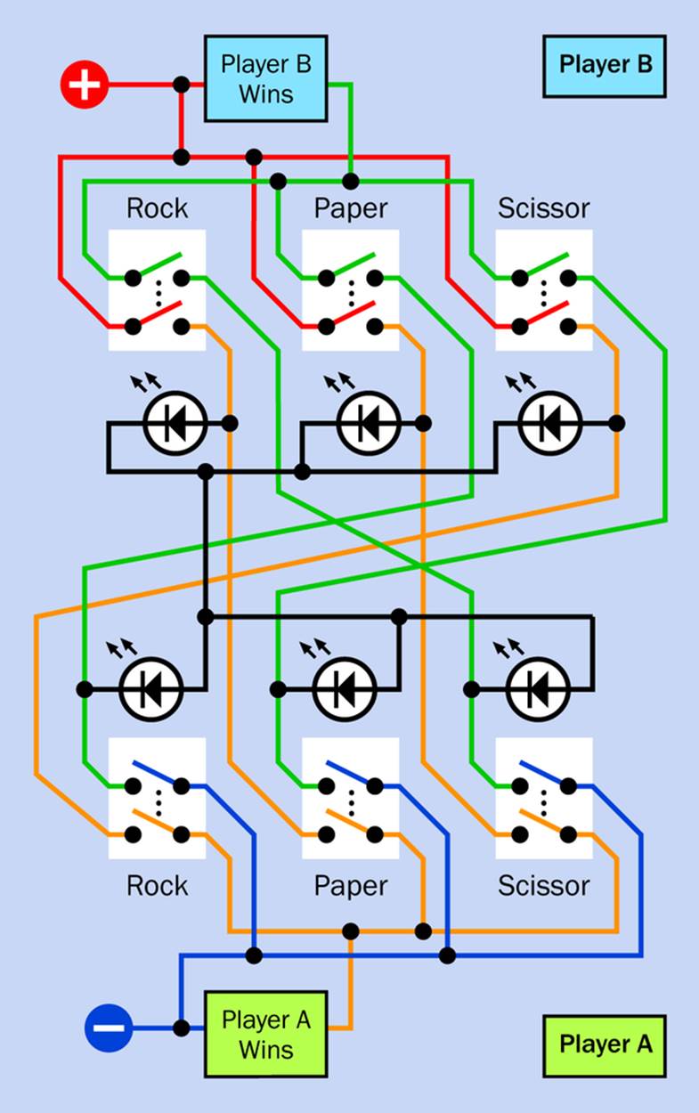
Figure 18-5. This configuration enables an LED to indicate which switch has been pressed, but only after both players have made their choices.
Figure 18-6 shows an example of how this circuit works, in a situation where Player B presses the “Rock” switch while Player A presses “Scissors.” The conductors that are now directly connected with positive are shown in red, while the negative connections are shown in blue. Inactive wires, switches, LEDs, and indicators are grayed out. The magenta wires carry a reduced current that has passed through one LED but has not yet passed through a second LED.
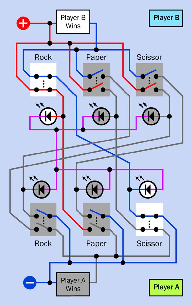
Figure 18-6. In this example showing how two switches illuminate the appropriate LEDs, Player B has chosen “Rock” while Player A has chosen “Scissors.”
A component needs to have positive on one side and negative on the other to be activated. Therefore the “Player B Wins” indicator lights up, while the “Player A Wins” indicator does not.
The current has to pass through one LED to get to another LED. Between LEDs, the wires are shown in magenta, as they have an intermediate voltage. If you think of the two LEDs as being in series, with positive at one end and negative at the other, you’ll see why the two LEDs adjacent to closed switches will light up, while the others remain inactive. Remember that because LEDs are diodes, they block voltage of the wrong polarity.
If you trace other switch combinations, I think you will find that each of them lights only the correct LEDs and indicators.
In an actual circuit, if you put two LEDs in series, and each LED is of the type that has a resistor built into it, you may find that the light output is unacceptably dim. This is because the current is passing through two LEDs and two resistors in succession. You can try using two generic LEDs wired in series without any resistors, and use your meter to check that the current is below the maximum specified for each component. Most likely, for optimum performance, you should use generic LEDs with a small-value resistor substituted for the vertical magenta wire on the left of the schematic, linking the two groups of LEDs. Choose the value of the resistor by trial and error, working from 220Ω downward, until the current is correct. Remember that while most LEDs are happy with a current of 20mA, some have a lower limit.
Cheat Proofing
Now for the hard part: cheat prevention. The way I’ve chosen to do this is by using the existing circuit with an additional switch configuration that controls the availability of power to the circuit for each player.
The principle of the thing is shown in Figure 18-7, where three double-pole switches are shown in different combinations. Note that all of these switches are normally closed. When you press a switch, you open it. To draw your attention, I have colored a switch green when it is being pressed to open it.
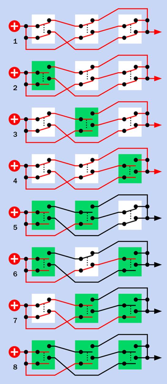
Figure 18-7. Wired in this way, three normally-closed double-pole switches will allow current to pass through when no switches or a single switch is pressed, but will block current when two or three switches are pressed. The green highlight indicates switch(es) that are pressed.
At the top, none of the switches is being pressed, so they all remain closed, and the electricity passes through. In the next three examples from the top, one switch at a time is being pressed, but the other two remain closed, allowing at least one pathway for electricity to pass through. In the next three examples, two switches at a time are being pressed (remember, green means the switch is being pressed), and the remaining unpressed switch is insufficient to connect power through the chain. In the final example, with all three switches pressed, the electricity is blocked.
The wires carrying current are shown in red. You can see that if no switches are pressed, or any one switch is pressed, power is connected, but if any two switches or all three switches are pressed, power is blocked. This provides an anti-cheating system that can be used in the Rock, Paper, Scissors game.
In Figure 18-8 the anti-cheating system has been added to the previous circuit, using an extra two poles on each switch. For the sake of clarity, I have only shown contacts that are being used in the circuit. I have not shown any unused switch contacts. Thus every switch shows two normally-open contacts and two normally-closed contacts.
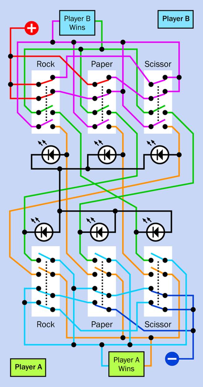
Figure 18-8. The previous circuit has been expanded to include an anti-cheating system, so that power is shut off when either player presses two or three switches instead of one. See text for details.
I have tried to clarify it with wire colors. Any wire that is permanently connected to the positive side of the power supply is colored red. Wires that normally carry positive voltage, through normally-closed switches, are magenta. If two or three switches are pressed simultaneously, the magenta wires no longer carry positive voltage.
Similarly, at the bottom end of the circuit, dark blue wires are permanently connected to the negative side of the power supply, while pale blue (cyan) wires will no longer have a connection to the negative side if two or more switches are pressed.
In this way, the system shuts off power to the circuit if either person cheats.
Fit to Be Tied
Lastly, do we need an audible signal if Annabel and Boris have a tied game by pressing buttons opposite each other? They’ll see from the pushbutton LEDs that the game is tied. Still, if you want a beep, it can be added. To do this without requiring an extra pole on the switches, you need three beepers. Fortunately they’re very cheap (some costing less than $1). You can graft them into your circuit as shown in Figure 18-9. The circular symbols show where the beepers go. They should be the polarized type, passing current in one direction, and they should be the kind that makes a sound when you apply a DC voltage. You don’t want a loudspeaker or the kind of beeper that requires you to feed an audio frequency into it.
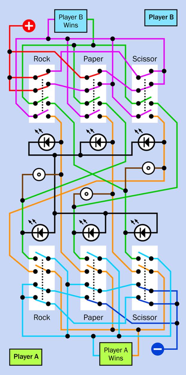
Figure 18-9. Each beeper (shown as a symbol consisting of two concentric circles) will sound if the two switches connected with it are closed, indicating a tied game.
Why do you need more than one beeper? Because if you only had one, you would have to run three wires to each side of it from existing switch contacts, and electricity would flow in through one wire and then out through any of the other wires. Consequently, any pair of switches would sound the beeper.
Wiring It
To build this circuit, you’ll have to use soldered point-to-point wiring. The pin spacing on the switches may be 0.1”, but if you inserted a switch into a breadboard, each pair of pins would end up sharing one lateral conductor on the board, making it impossible to power them individually. The switches that I’ve seen are narrower than a through-hole chip, and therefore cannot straddle the central channel in the board.
A computer rendering of a typical 4PDT pushbutton switch is shown in Figure 18-10. The red labels that begin with letter P are the pole connections of the switch. The four sets of contacts that match the four poles are labelled C1, C2, C3, and C4. NC means that the contact is normally closed, while NO means that it is normally open. Whether you use a spring-loaded pushbutton or one that you press twice is up to you. This type of switch is often referred to as a “slider,” because the internal contacts slide.
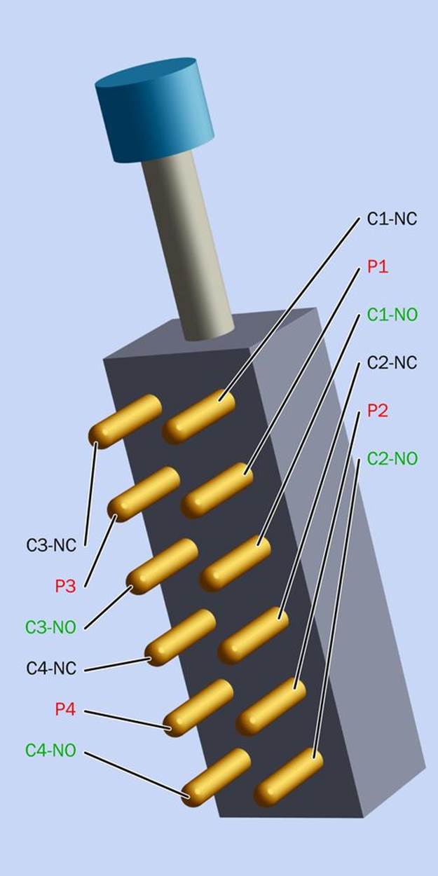
Figure 18-10. The pinouts of a typical 4PDT slider switch. The poles are numbers P1 through P4, while contacts are numbered C1 through C4. Normally-closed contacts are labelled NC, while normally-open contacts are labelled NO.
Two typical schematic symbols representing a 4PDT slider switch are shown in Figure 18-11. The labels match the labels on the 3D rendering of the switch. On the righthand side, the vertical gray bar consists of an insulating material with conductive sections added to it, shown in black. These black sections short together the contacts adjacent to them. When the bar is pushed down by the plunger of the switch, it shorts a different pair of contacts. You may find either of these types of symbols being used in manufacturers’ datasheets.
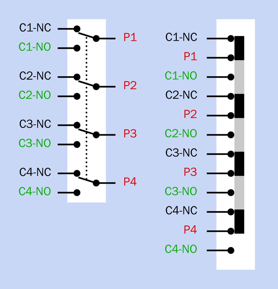
Figure 18-11. Two commonly used schematic symbols to represent a 4PDT slider switch.
Figure 18-12 shows how to hook up the switches to make the Rock, Paper, Scissors game. Pins that have soldered connections with wires are shown solid black, while unused pins are white. A few of the wires have been moved around relative to the schematic shown previously, to minimize crossovers and avoid any locations where three wires meet on a pin. Such locations are more difficult to solder.
This circuit lacks the cheat-detecting feature, in case you want to keep things relatively simple (initially, at least). The wire colors match the colors that I used in the schematics, but of course any colors will do. Notice that the switches at the bottom are upside down relative to the switches at the top. This is because you may want to mount them on opposite sides of a box or board, in which case the switches will be rotated relative to each other.
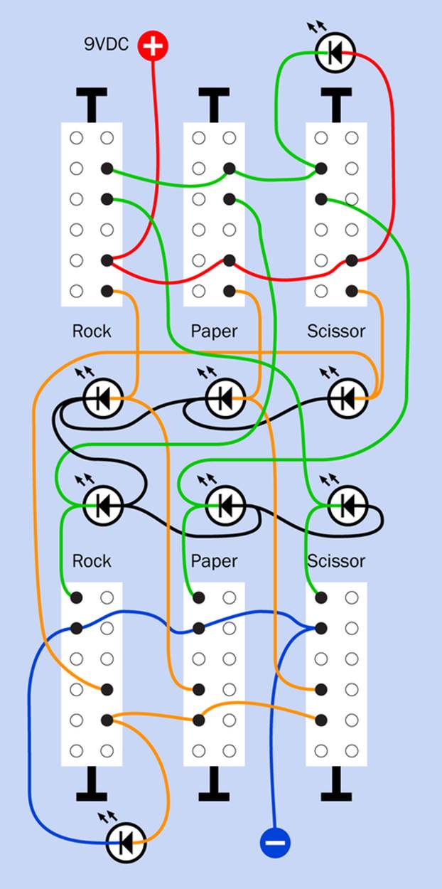
Figure 18-12. Wiring six 4PDT slider switches for the simpler version of the Rock, Paper, Scissors game, which does not include cheating prevention. Series resistors for the LEDs are not shown.
Soldering wires to the switch pins requires some care to avoid solder bridges that will cause short circuits. I think you’ll have an easier time if you use wire that is thinner than the 24 gauge that I have recommended for breadboarding work. Personally I like to use rainbow-colored ribbon cable, which can be pulled apart into separate colored conductors. The stranded wire is flexible, making it easy to work with, although the result may look a bit messy.
Figure 18-13 shows the underside of a board that I soldered myself. My soldering is not the neatest, but the object here is to build something that works, and the board does work.
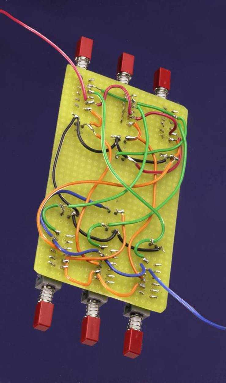
Figure 18-13. The underside of a rectangle of perforated board showing the slider switches wired without the “no cheating” feature.
I used 12V LEDs that contain their own series resistors, which is why you don’t see any resistors in the wiring. I was pleased to find that I could power two of these LEDs in series, and they would still be bright enough, even though the power inevitably goes through two of the internal resistors in addition to two of the LEDs.
Figure 18-14 shows the top side of the same board. I left the LED leads long, because the idea is to push the LEDs up through holes drilled in the lid of an enclosure, while the pushbuttons will be accessed through holes in the side of the enclosure. At the time of writing, I haven’t gotten around to building this box. The red LEDs indicate which switch has been pressed, while the LEDs that look gray are actually blue when they light up, indicating which player has won the game.
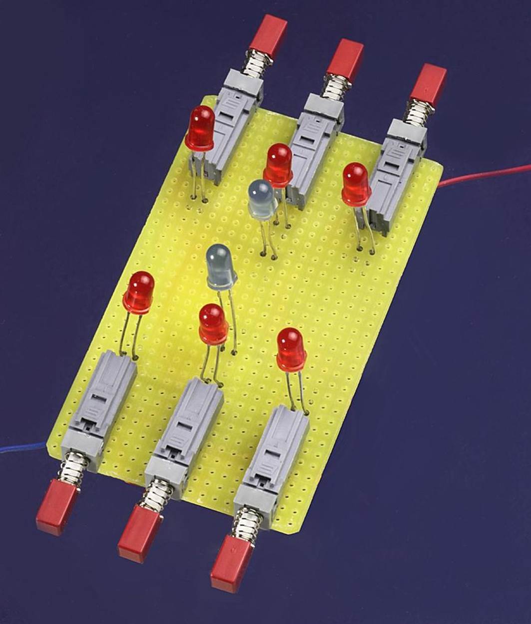
Figure 18-14. The top of the rock-paper-scissors circuit. The LED leads were left long so that they could be pushed up through holes in the lid of an enclosure.
I’m suggesting a 9VDC power supply for this project, because it will use no electricity at all until two buttons are pressed, and even then the LEDs will not use much power. If they are rated for 12V, they will look okay with a 9V battery.
If you use generic LEDs that require external series resistors, you can use 470Ω resistors for the single LEDs that show who wins a game, but I don’t know what value resistors you will need with the LEDs that are wired in series. If you reduce the series resistor to make the LEDs brighter, be careful not to exceed the maximum forward current recommended in the datasheet.
A version of the game that uses two pieces of perforated board, on opposite ends of a box that has LEDs mounted in the top, is shown in Figure 18-15. This configuration hides each person’s switches from the other person. A 9V battery is dimly visible inside the box, clamped under a piece of plastic. Replacement will require removing some of the screws, but the battery should be good for a couple of years if the game isn’t played too often.
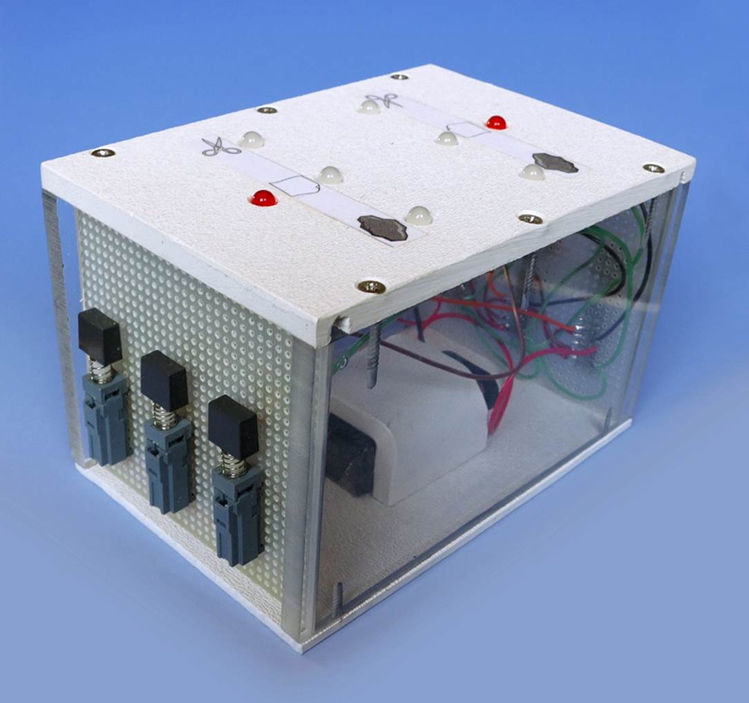
Figure 18-15. A finished version of a Rock, Paper, Scissors game using switches only.
Cheat-Proofed Wiring
Figure 18-16 shows the switches hooked up including the cheating-prevention feature. It really doesn’t add much to the soldering time and is a nice feature to have. If you already wired the un-cheat-proofed version, the only wires you will have to change are the blue and red ones that provide power. Everything else is additional.
If you also want to add beepers, I’m going to leave that to you.
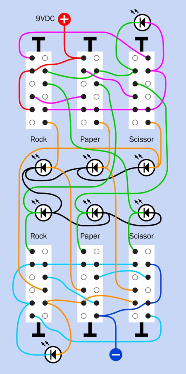
Figure 18-16. Wiring diagram for the enhanced, switched version of the Rock, Paper, Scissors game, including cheating prevention.
The underside of the perforated board with cheat-proofing wiring added to it is shown in Figure 18-17.
Conclusion
Switches looked simpler than logic gates to begin with, but in the end, they turned out to be complicated in a different way.
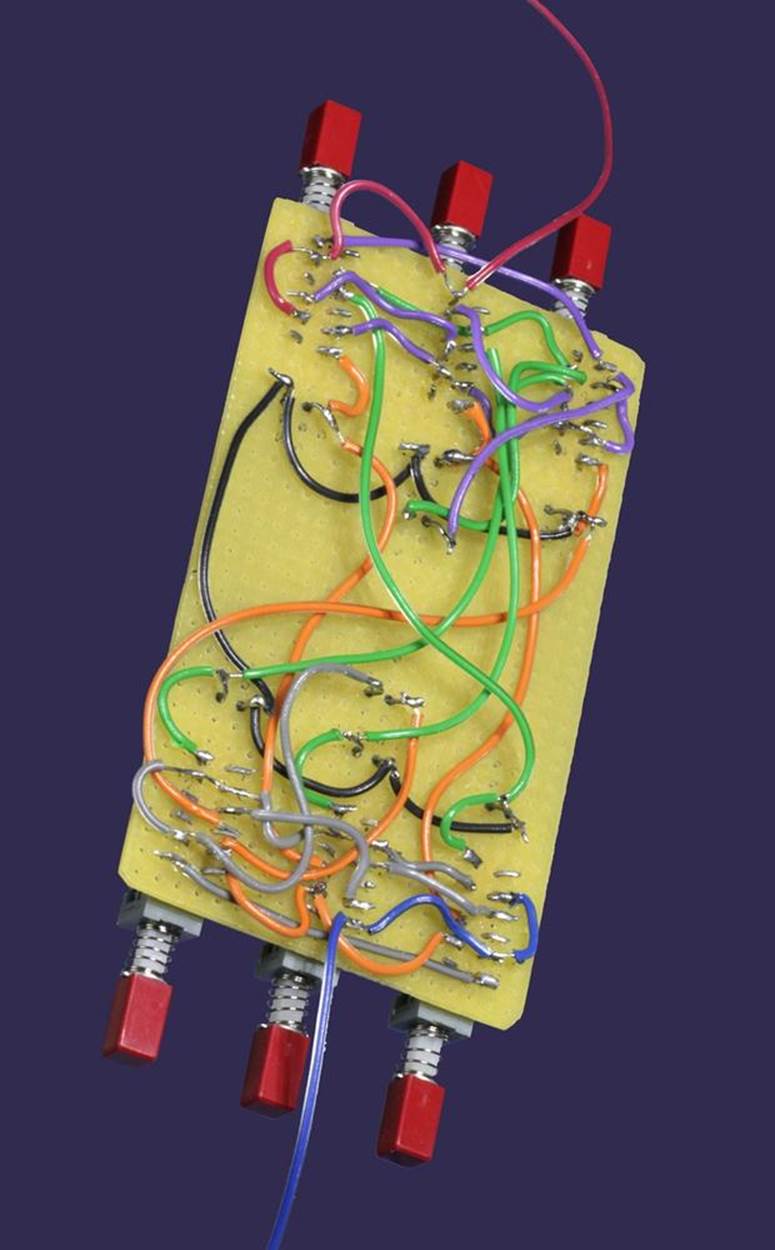
Figure 18-17. The same board shown previously, now with cheat-proofing added.
Logic gates can be assembled in a manner that is—well, logical. You write down what you want, using ANDs and ORs, and then represent it in a diagram with AND and OR gates (and other gates, if necessary). Finally you choose some chips containing the appropriate gates and link them together in the same way that you drew your diagram. This is not a big challenge.
The problem with logic gates is that because each one is not very powerful, you need a lot of them. Consequently, the circuit requires a lot of components, becomes confusing, and can encourage wiring errors.
Switches have several advantages. They’re simple, they’re easy to understand, they don’t require any power when they’re off, and they can conduct a lot of power (relatively speaking) when they’re on. I like the idea of a circuit that doesn’t need an on-off switch because the switches are the circuit!
The problems start when you want the circuit to perform multiple functions. This inevitably leads to multiple-pole switches, and the tangle of wiring may have unpredictable results unless you’re really careful. If you want to optimize the circuit, you have to be even more careful.
Most problematic, you need a strange kind of intuitive ability to design a circuit entirely from switches. There’s no equivalent of the logical system that enables a circuit of chips to be derived from a verbal description using ANDs and ORs. Really, it’s rare for anyone to try to build a useful circuit using only switches. I included this one just so that you could get a sense of what’s involved.
Are there any options other than logic gates and switches? Absolutely! There are three possibilities:
1. You can use relays. Many years ago, entire telephone systems were relay based. You might assume that a logic circuit using relays can be very similar to one using transistors, because the components behave similarly. But don’t forget that a relay can have multiple poles, like a switch, enabling one input signal to energize multiple separate outputs.
2. You could introduce a decoder, which I mentioned before. It contains a whole bunch of prewired logic gates so that you don’t have to deal with them individually. I’ll deal with decoders in detail in the next two experiments.
3. Yet again, you can use a microcontroller. In the Rock, Paper, Scissors game, as in the Telepathy Test, a microcontroller would make things much easier. But, as in the Telepathy Test, you wouldn’t learn much about logic.
All materials on the site are licensed Creative Commons Attribution-Sharealike 3.0 Unported CC BY-SA 3.0 & GNU Free Documentation License (GFDL)
If you are the copyright holder of any material contained on our site and intend to remove it, please contact our site administrator for approval.
© 2016-2026 All site design rights belong to S.Y.A.