Make: More Electronics (2014)
Chapter 21. Experiment 21: The Hot Slot
Previously, I mentioned that because a coin has no memory, it has the same chance of showing heads or tails every time you flip it. (See Chapter 17.) The odds are always the same. Likewise, the traditional “wheel of fortune” doesn’t remember where it stopped on the previous spin, and provided it is turned randomly each time, the odds of any number coming up never vary.
Not all games are like this. If you’ve ever played Battleship, for instance, you know that your odds of success will vary during the game, especially if you reach a point where you have eliminated a lot of empty squares, leaving your opponents’ ships nowhere to hide.
I decided to create a two-player coin game with variable odds. Initially the stake would be low, and the odds of winning would be low—but as each player added more coins, the jackpot would get bigger and, at the same time, the odds of winning would gradually improve. I thought this should create some tension and drama in the game, even if it was just played for tokens rather than money.
This is how the Hot Slot game came to exist.
If you read Make magazine, you may remember that one of my columns discussed a game in which coins were used to complete an electrical circuit and win a prize. The Hot Slot game shares that basic concept, but in every other respect, it’s very different.
Muxing It
This game enables me to keep my promise to introduce you to a multiplexer. “Mux” is the colloquial term that people often use for this component.
Many variants exist, but the one I chose for this experiment is the 4067B. It’s an old-school CMOS chip, although unlike many CMOS components of its era, it is not restricted by low output current. You can think of it as merely serving as a channel through which you pass current.
Plug the 4067B into your breadboard, and add four switches and pulldown resistors as shown in Figure 21-1. This is very similar to the test circuit for investigating the 4514 decoder (see Figure 19-3), except that instead of sixteen output pins, we now have sixteen “channel” pins that can function as inputs.
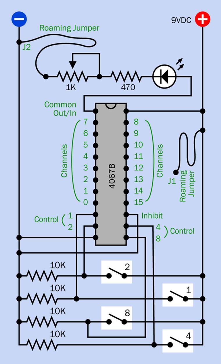
Figure 21-1. A simple circuit to test an analog multiplexer.
The switches are at the bottom because the pins that are associated with the switches are also at the bottom end of the chip. This keeps the schematic as uncluttered as possible.
You don’t need a meter to test the multiplexer, because it’s quite happy to drive an LED. This is attached to pin 1, known as the “Common Out/In” pin for reasons which I will explain in a minute. A series resistor protects the LED from excessive current, and a trimmer potentiometer will demonstrate that we can vary the current.
The wire attached to the trimmer has wiggles in it to suggest that it is a flexible jumper wire—the type that you should generally avoid, with a little plug on each end. I’m calling it a “roaming jumper” because I want you to be able to move it around. Right now, the end of it labelled J2 is plugged into the negative-ground bus. If you don’t have a jumper wire of this type, you can use a length of solid-core 24-gauge hookup wire, with a quarter inch of the insulation stripped at each end.
At the right side of the schematic, you see another “roaming jumper.” I want you to be able to touch the end of it, labelled J1, to any of the channel pins that have values 0 through 15.
You can power this circuit with 9VDC from a battery. The voltage does not have to be regulated, and you don’t need any smoothing capacitors. However, CMOS chips are sensitive to static electricity, so take the usual precaution of grounding yourself before handling it.
Jumping and Roaming
Now, let’s see what happens if you close the two switches labelled 2 and 4. If they work the same way as the switches that were used with an encoder, they should activate the channel that has value 6, because the channel number is determined by adding the values of the switches that are closed.
Sure enough, if you touch jumper J1 on channel pin 6, you should see the LED light up. Positive power is flowing from the bus, through J1 and into the channel with value 6. An internal connection in the chip takes the power to the Common Out/In terminal, at pin 1. From there it travels through the LED and the series resistors, and out of J2 into the negative bus.
Adjust the 1K potentiometer, and the LED brightness will vary. Note that you are not just adjusting the output power; you are adjusting the power flowing through the whole chip. You can add a meter, set to measure mA, in series with J1, and you’ll find the current is varying on the input side as well as the output side.
You do pay a small penalty for this service. The chip deducts a percentage of the voltage for its own purposes. You can prove this by setting your meter to measure volts and applying it between pin 6 and the Common Out/In pin.
Now here’s the interesting part:
§ Touch J1 on any of the other channel pins, and the LED should stay dark.
§ If you change the switch combination, a different channel pin will become active.
Turn on all the switches, for instance, and the sum of their values (8 + 4 + 2 + 1) will activate the pin that has a value of 15.
What have you learned so far? And what else do you need to know?
Quick Facts About Muxes
§ This mux has four binary-valued control pins, like a decoder.
§ But it seems to be the opposite of a decoder. Instead of delivering power out of a pin with value 0 through 15, it accepts power into a pin with value 0 through 15. These pins are connected inside the chip through “channels.”
§ The pattern of high/low states on the control pins selects one of the channels.
§ The selected channel will pass an input current through to a common pin.
§ The channels which are not selected will not pass current. (Actually there is a little leakage, but it is negligible.)
§ Maximum current input is 25mA, but this value becomes lower as the voltage goes up. Each passthrough transistor is rated for a maximum of 100mW.
§ The power supply can range from 3VDC to 20VDC.
§ The voltage that you apply to a channel cannot be higher than the power supply voltage or lower than negative ground.
§ A good way to think of a multiplexer is to imagine it as a solid-state rotary switch, as suggested in Figure 21-2. In this figure, control pins with values 2 and 8 have been arbitrarily selected, making an internal connection between channel 10 and the common output/input.
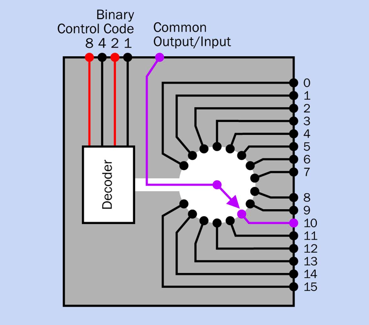
Figure 21-2. A multiplexer works like a solid-state rotary switch. The purple connection is established by the binary code applied to the control inputs.
Mux Pinouts
Pinouts for the 4067B are shown more formally, along with pin numbers, in Figure 21-3. The control pins are labelled 1, 2, 4, and 8, as these are their binary place values. (In a datasheet, these pins may be labelled A, B, C, and D.) The channel pins are labelled Chan 0 through Chan 15. (A datasheet may refer to them as Y0 through Y15, or similar.)
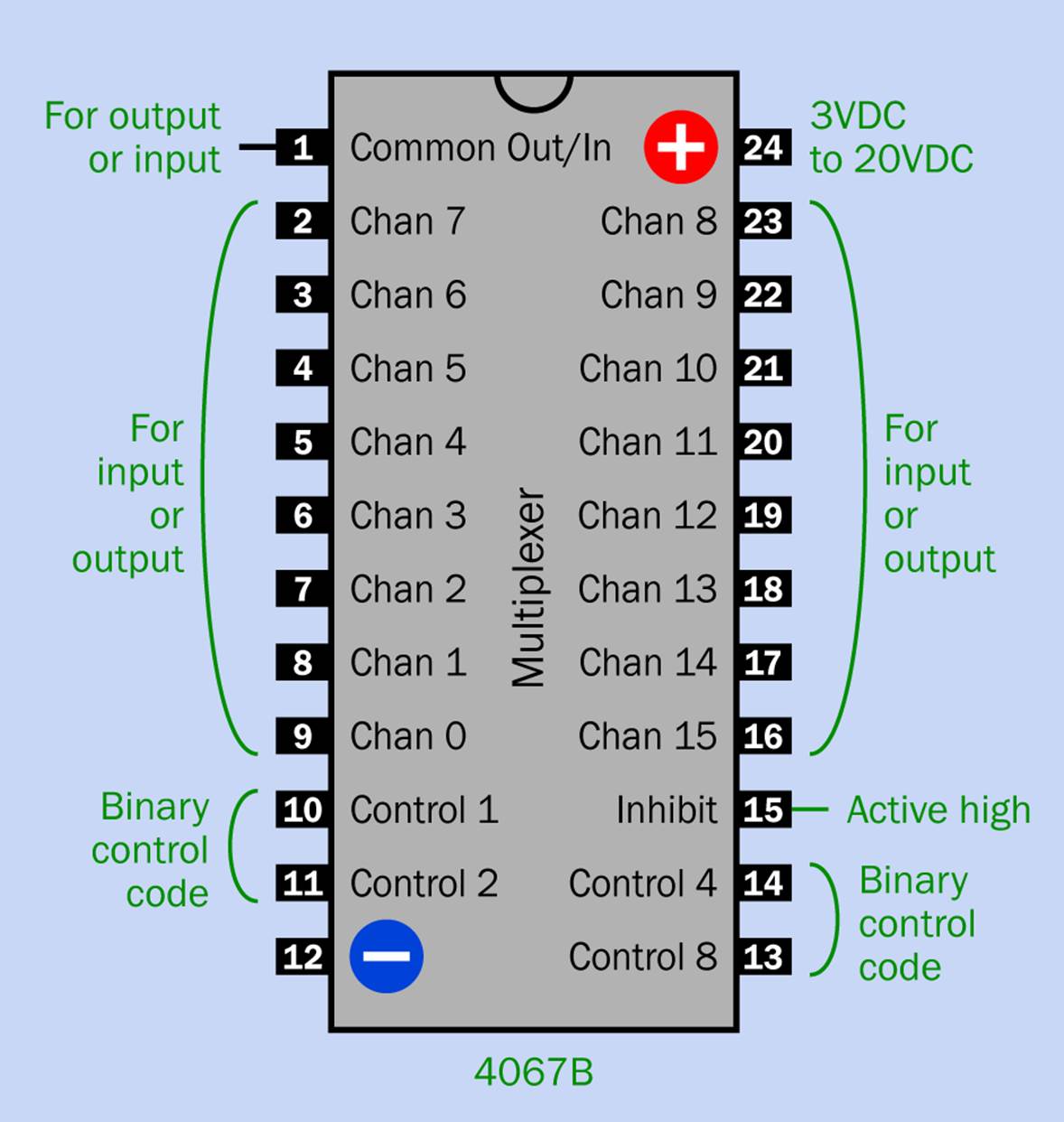
Figure 21-3. Pinouts for the 4067B multiplexer.
In addition to the pins that I have described so far, there’s an inhibit pin, located at Pin 15. This is active high, meaning that if you connect it to positive voltage, the chip will be inhibited from responding to the control pins. I don’t want this to happen, so in the test circuit, the inhibit pin is tied to ground. You can experiment by connecting it with the positive side of the power supply, at which point the chip will switch off its internal transistors.
Mux Applications
I’m going to use the multiplexer in the coin game that I have in mind. But what is it normally used for?
Consider its capabilities. Depending on its control input, it can select one of up to sixteen inputs and send the signal out through a common pin—very quickly. In fact it works so quickly, it can take two or four or more separate telecommunications signals on the channel pins and sample them one at a time, in sequence, combining them into a single output channel. Thus, one wire can carry two, four, or more signals. Of course at the other end, you need to split the incoming stream back into its original channels. For this purpose you need . . . a demultiplexer!
The same multiplexer that I’ve been talking about, the 4067B, can also function as a demultiplexer, because it is a bidirectional chip. This is why the channel pins in the pinout diagram are labelled “For input or output,” and is why the Common pin is labelled “Out/In.” The mux doesn’t care which way the current flows through it.
You can prove this for yourself by modifying your test circuit slightly, as shown in Figure 21-4. Roaming jumper J1 is now plugged into the negative bus, while jumper J2 is plugged into the positive bus, and the LED has been turned around so that it responds to current flowing in the opposite direction.
You may wonder why a multiplexer isn’t called a multiplexer/demultiplexer, since that’s what it does. Well, if you look at a datasheet, it usually is called a multiplexer/demultiplexer—but this is such a mouthful, people just call it a mux.
A mux is also used where we need to switch more slowly between multiple inputs. Inside a computer, for example, it can select one of two or more video outputs.
In a stereo system, it can select among inputs from a CD player, a DVD player, an MP3 player, or some other audio source. Depending on the code applied to the control pins, the mux will choose one input and connect it with the common output pin. This used to be done with an electromechanical rotary switch or pushbuttons, but a solid-state switching device is more reliable and shouldn’t introduce noise of the type that is characteristic of switch contacts.
A stereo system has two audio channels (more, if you have a home theater system with Dolby 5.1). To address this requirement, you can buy multiplexers that contain two or more switches, both governed by the same set of control pins. These multiplexers can be compared with a rotary switch that has several decks, all governed by the same control shaft and knob.
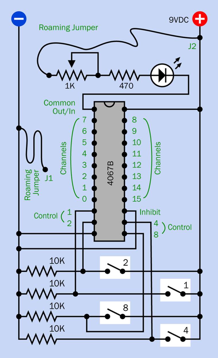
Figure 21-4. With Jumper J2 plugged into the positive bus, you can demonstrate the bidirectional capability of the multiplexer by using J1 to sink current into the negative bus. Don’t forget to reverse the LED so that its polarity matches the current flow.
Analog Versus Digital Mux
The 4067B is an analog multiplexer. This means that it can pass and preserve AC signals, which oscillate above and below a neutral value. For example, you could hook up a multiplexer to a simple audio intercom and distribute its output to a variety of rooms in your house.
Digital multiplexers are also available. Their inputs must be within the usual high/low range for logic chips. The digital multiplexer then uses a binary code on its control pins to select one channel (just like an analog multiplexer), and senses whether it is high or low. But the chip generates its own output signal, to make sure that the output conforms with digital specifications.
A digital multiplexer is not reversible. The channels receive inputs, the Common pin provides an output, and that’s the end of the story. AC signals cannot be used.
Since a digital mux is not reversible—what do you do if you want to decode its output at the other end? Well, you use a decoder! The control inputs on a decoder can be synchronized with the rate at which data packets are flowing in so that it chops the stream into segments of the correct size.
A decoder is really the same thing as a digital demultiplexer, although that term is seldom used. Meanwhile a digital multiplexer is similar to an encoder. This is why electronic parts suppliers often put encoders, decoders, multiplexers, and demultiplexers all in the same category. The supplier doesn’t try to disentangle all the different varieties. It just shows you all the options and says, “You figure it out.”
To assist you in this, here’s a summary.
Quick Facts About Mux Variants
§ A decoder can have two, three, or four control pins. A binary code on these pins selects one output pin from a series that have values from 0 upward. The selected pin has a logic-high output. The other output pins are logic-low. The decoder is a digital device using high and low logic states. Its input/output direction is not reversible.
§ An encoder is the opposite of a decoder. It has multiple inputs, each of which is assigned a decimal value, from 0 upward. Only one pin at a time should have a logic-high input. The encoder converts the value of this input into a two, three, or four-bit binary number which it outputs through two, three, or four output pins. It is a digital device using high and low logic states. Its input/output direction is not reversible. (We have not encountered an encoder in this book, yet. But we will.)
§ A digital multiplexer is similar to an encoder, in that it receives an input from one of a sequence of pins, each of which is assigned a decimal value, from 0 upward. However, it has a single common, or output, pin. The binary states of two, three, or four control pins determine which input pin is connected with the output pin. It is a digital device using high and low logic states. Its input/output direction is not reversible.
§ An analog multiplexer is similar to a digital multiplexer but does not create its own output voltage. This is the device that you tested in the experiment above. It merely passes the status of a selected channel pin through to a Common pin, via an internal connection. In this way, it functions as a digitally controlled, solid-state rotary switch. It will work with AC or DC signals over a wide range of voltages, and its current flow is reversible.
§ An analog demultiplexer is usually just an analog multiplexer which is used in reverse so that the Common pin is used as an input and a Channel pin is selected as the output.
§ A digital demultiplexer is usually the same thing as a decoder.
Game Design
I had to go through a lot of explanation before I could get back to building the Hot Slot game. Anyway, here’s the way I’m imagining the game. I’ll have a box with sixteen slots in it, each slot large enough to hold a coin. When a coin is inserted in a slot, the coin will create an electrical connection between two internal contacts.
One of the slots will be chosen at random to have live contacts. This will be the Hot Slot. It will be energized via a multiplexer, before the game begins, and the two people who are playing the game will have no way of knowing which it is.
A player’s turn consists of placing one coin in a slot. If it isn’t the Hot Slot, nothing happens, and the other player places a coin. Players take turns until someone hits the Hot Slot, at which point a beeper will sound. The winning player then takes all the coins that have been placed in the slots. One of the players then resets the game by pressing a button. The mux chooses a new Hot Slot, and the game repeats.
In Figure 21-5 you will see a simple flow diagram showing how this can be done. A 555 timer will be running in asynchronous mode, generating maybe 50,000 pulses per second—that is, 50KHz. The timer will drive a counter chip that counts from 0 through 15 over and over again, delivering its output as a series of four-bit binary numbers. These four-bit numbers will be wired to the four-bit control input of the multiplexer.
A player will allow the counter to run by pressing a button, and will stop the counter at an arbitrary moment. This is how a slot number will be selected randomly. I used a similar approach in Make: Electronics, so if you read that book, the scheme should be familiar.
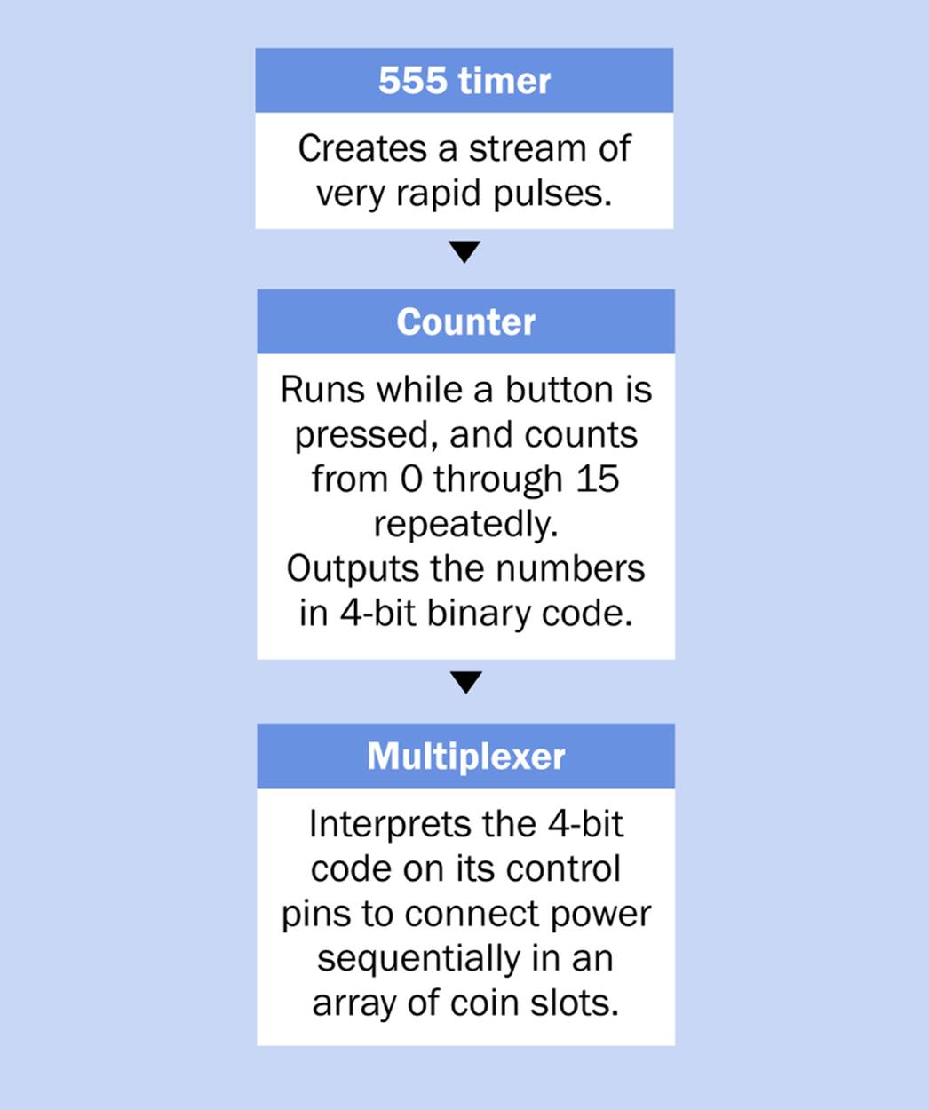
Figure 21-5. The system to choose a random number which will be interpreted by a multiplexer, to choose one of sixteen coin slots.
Slot Counting
I want to use a 9VDC power supply for the multiplexer to minimize the effect of its internal resistance. Is there a counter chip that can be powered by 9V? Yes, indeed. The 4520B counter is another old-school CMOS component which is still being manufactured in large quantities. Its pinouts are shown in Figure 21-6.
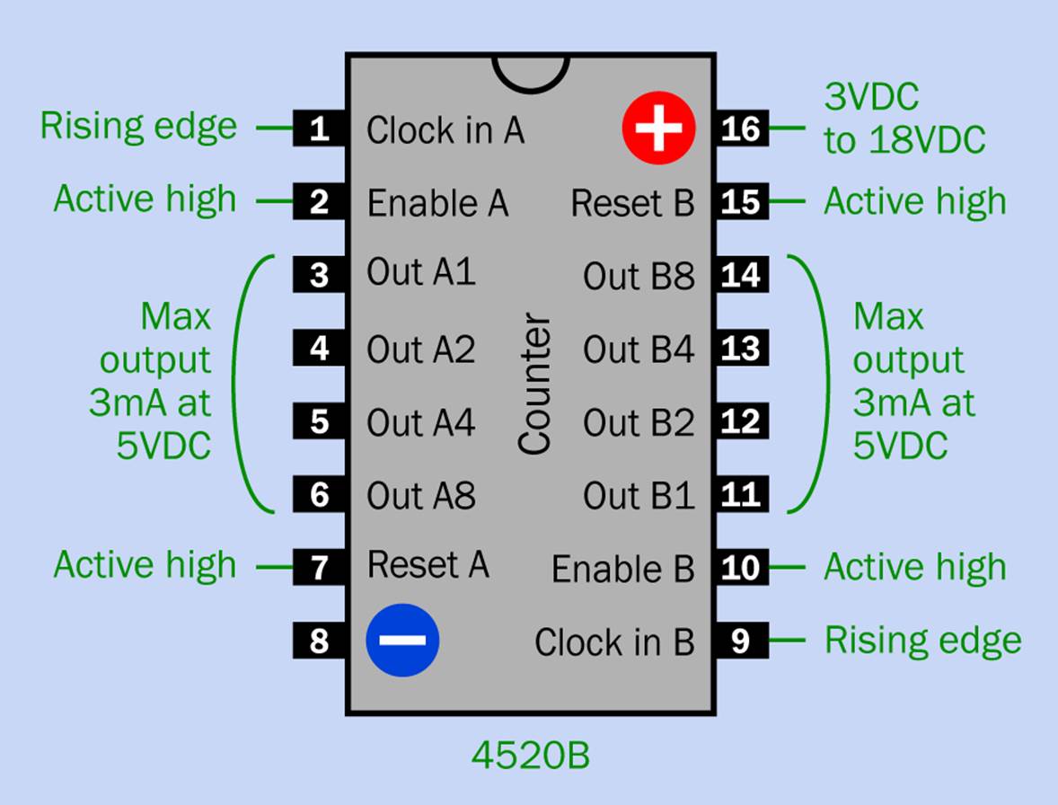
Figure 21-6. The pinouts for a CMOS 4520B chip, which counts repeatedly from 0 to 15 decimal and expresses the running total as a four-bit binary output.
The 4520B actually includes two 4-bit counters, which can be chained together to make an 8-bit counter capable of counting from 0 through 255. We only need four bits, so I won’t use the second half of the chip.
In Figure 21-6 I have arbitrarily designated one counter as “A” and the other as “B.” Manufacturers’ datasheets may identify them this way, or may label them differently. I have also designated the outputs according to their binary place value (1, 2, 4, and 8). Datasheets may commonly designate them as Q1, Q2, Q3, and Q4, or some similar numbering scheme. There is no standardization.
The Reset pin (which is active high) sets all the outputs to 0, which is of no interest to us, because we want a random, arbitrary output. Therefore the Reset should be tied permanently to the negative side of the power supply in the Hot Slot game, to disable it.
The Enable pin is also active high, meaning that the counter will run when positive power is applied to Enable, and will freeze when Enable is connected to negative ground. This feature will be used in the Hot Slot schematic to stop the counter, to choose a slot at random.
The Clock pin advances the counter when the signal on the pin transitions from low to high. (If a high-to-low transition is required, the clock signal can be applied to the Enable pin while the Clock input is held low. This feature is of no interest in the Hot Slot game.)
Circuit Design
You can now build the circuit for picking a random number from 0 to 15. The breadboard section is shown in Figure 21-7.
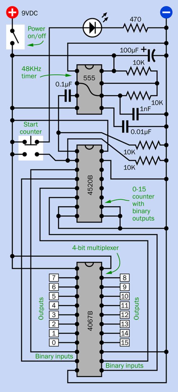
Figure 21-7. The breadboard section of the circuit for the Hot Slot game.
The counter and the multiplexer are both CMOS chips of similar vintage, so they should talk to each other without any problems. They should also be compatible with the output from the 555 timer. The only potential source of trouble is the tendency of a bipolar 555 timer to create voltage spikes, which can be picked up by the counter and misinterpreted as clock cycles. Placing a 100µF capacitor between the power supply pin of the timer and negative ground should deal with that issue. Make sure the capacitor is as near to the power supply pin as possible, and keep the leads of the capacitor as short as possible.
When the power switch at top-left is turned on, the LED is illuminated, and the 555 timer immediately starts sending clock pulses through the coupling capacitor to the 4520B counter. However, a 10K pulldown resistor on Pin 2 of the counter (the Enable pin) prevents the counter from counting.
To select a random number, the pushbutton must be pressed. This connects Pin 2 of the counter directly to the positive bus of the power supply, overriding the pulldown resistor and enabling the counter, which responds to the stream of pulses from the timer. When the pushbutton is released, the counter is disabled again, stopping at a randomly selected number. The LED comes on, indicating that the game is ready.
The number at which the counter has stopped is supplied to the 4067B multiplexer, which makes an internal connection between the corresponding channel pin and the common out/in pin. This receives power from the positive bus. Power from the bus goes out through the Channel pin (so the multiplexer is really behaving as a demultiplexer, if you want to be precise about it).
The sixteen channel pins are connected with the sixteen coin slots, which are depicted in Figure 21-8. The numbers down the left edge of this schematic indicate connections with the same-numbered channel pins of the multiplexer.
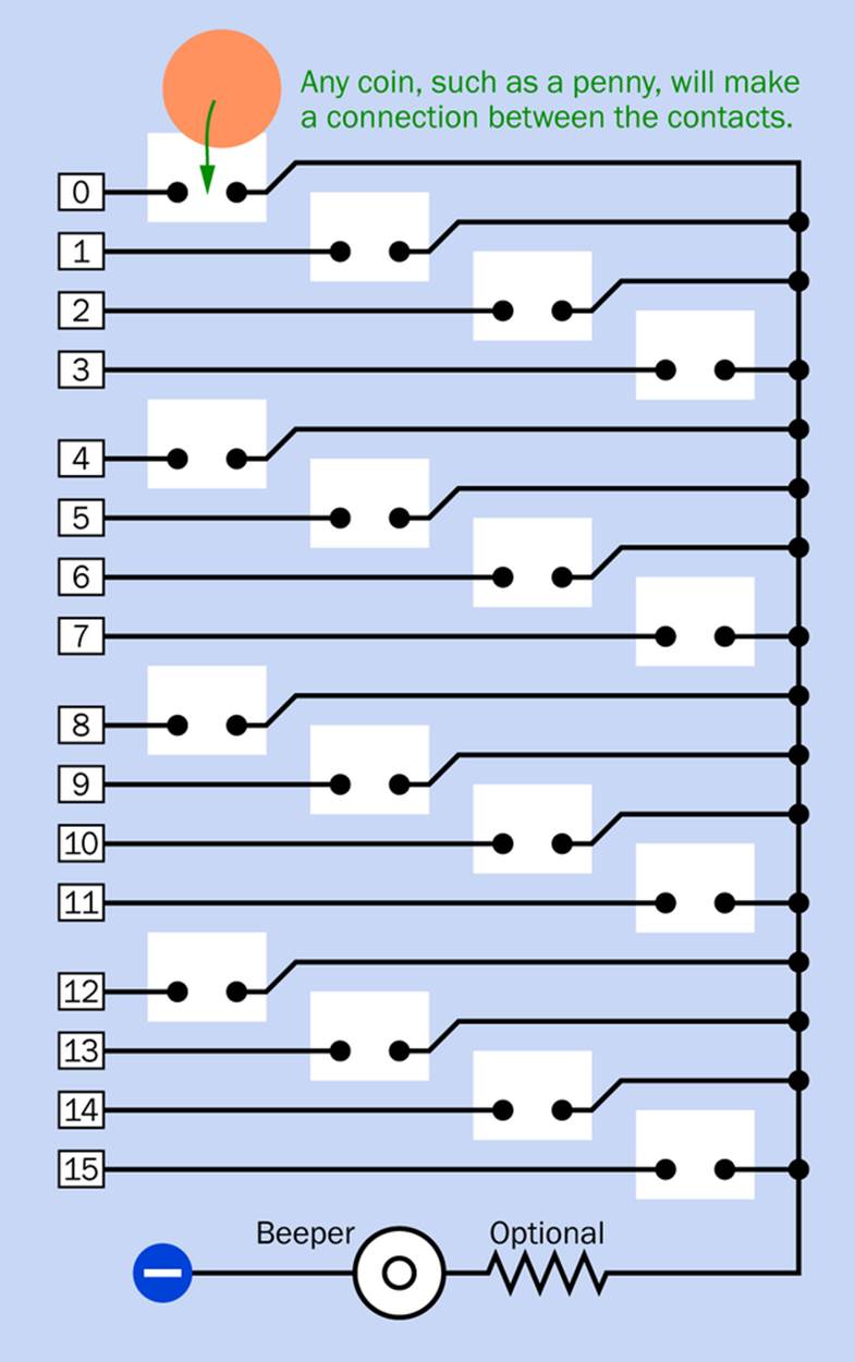
Figure 21-8. In this schematic, each pair of contacts indicates a coin slot in the Hot Slot game. A coin makes an electrical connection between the contacts.
Because only one channel at a time receives power from the multiplexer, only one slot is ever active. When a coin is inserted in that slot, it connects current through the beeper to negative ground. This ground must come from the negative ground on the breadboard to complete the circuit. A resistor may be placed in series with the beeper if necessary to limit its power consumption to around 15mA to avoid overloading the multiplexer.
When the coins are removed, the beeper stops. The button on the breadboard must now be pressed again, to choose a new random number; otherwise, the slot that was energized in the previous game will still be the same.
Building the circuit for the Hot Slot game is actually the easy part, as it only contains three chips. Fabricating the coin slots is more of a challenge. If you just want to test the circuit without going to this trouble, you can use two eight-contact DIP switches instead of coin slots, and close them one at a time to simulate the process of adding coins. This is shown in the breadboarded version of the game in Figure 21-9. I’ve used flexible jumper wires to connect the multiplexer with the DIP switches, because I regard these as temporary connections. Ideally a 17-conductor ribbon cable should be used (the 17th conductor would be a ground connection from the switches back to the main circuit).
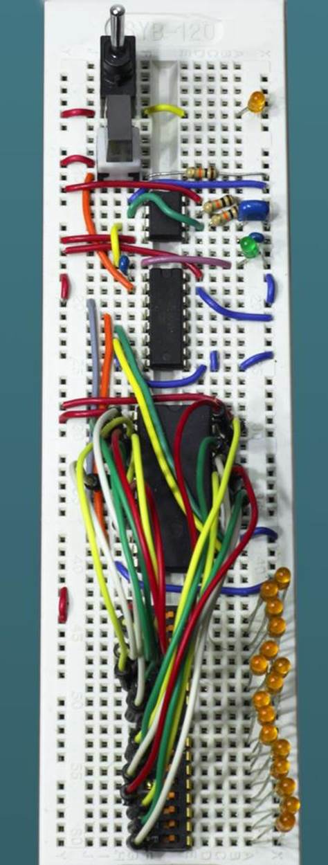
Figure 21-9. The breadboarded version of the Hot Slot game, using DIP switches as a substitute for coin slots.
Slot Design
In my Make magazine feature using coins in slots, I suggested the slot design shown in Figure 21-10, using small sections of thin aluminum angle cut from a length that I bought in a hardware store. Naturally, for sixteen slots, you would need to make four copies of this assembly.
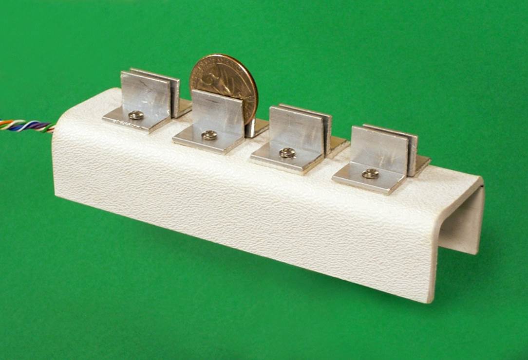
Figure 21-10. A simple type of coin slot for the Hot Slot game that can be made relatively easily while providing a reliable contact with the coin.
You can substitute a small section of wood for the ABS plastic that I used, and the slots can be installed in a box with corresponding apertures in the top. If you can come up with a more elegant slot design that does not require the coin to be jammed into place, I encourage you to do so. Eventually I’m going to modify this project with infrared sensors that will detect the presence of coins, but that won’t be until Experiment 31.
Hot Slot Testing
When you test the circuit, I suggest you begin with a larger value, such as 47µF, for the timing capacitor connected with the 555 timer to make it run slowly. Add LEDs (sharing a 1K series resistor so they don’t disturb the voltages in the circuit) to the output of the timer and the four outputs from the counter.
When the DPDT pushbutton in the schematic is not being pressed, use a meter to find which channel from the multiplexer is energized, and make sure its value matches the value of the binary input.
Once you are sure that the game is functioning correctly, substitute the correct capacitor to increase the timer speed, remove the LEDs, and you’re ready to play.
Who Wins?
Assuming that the circuit does what it’s supposed to do, there’s still one very important unanswered question: when two people are playing the Hot Slot game, does each of them have an equal chance of winning? Or does the person who goes first (or second) have an edge?
Figuring this out is like the process of designing a logic circuit. The first step is to describe the game very clearly:
§ The person who places the first coin has sixteen slots to choose from, and only one of them will win the game.
§ Therefore, he has a 1-in-16 chance of ending the game on the first turn.
Turning it around, there is a 15/16 chance of the first player not hitting it. In that case, the second player takes his turn. Fifteen slots are still available, and therefore the second player has a 1-in-15 chance of winning.
How likely is it for the game to end on the second turn? Two things have to happen:
§ The first player has to miss the hot slot. There is a 15/16 chance of this.
§ The second player has to hit the hot slot. There is a 1/15 chance of this.
To find the probability of both of these events happening, we must multiply the odds together. If C is the chance of the game ending with the second turn:
C = 15/16 * 1/15
If you remember your high-school math, the 15s cancel out, so:
C = 1/16
§ In other words, there is a 1-in-16 chance of a game ending on the second turn.
I’ll take this one step farther. The chance of Player 2 winning the game on the second turn is 1/15, so the chance of him not winning is 14/15. If that’s the way it works out, Player 1 now tries again, and because fourteen slots are still open, he has a 1/14 chance of ending the game on the third turn. If C is the chance of this happening:
C = 15/16 * 14/15 * 1/14
The 15s and the 14s cancel out, so:
C = 1/16
In fact, the chance of a game ending on the first turn, or the second turn, or any turn up to and including the sixteenth turn, is always 1/16.
I’m not saying that the odds of hitting the hot slot always remain the same at the moment when you place a bet. On the contrary, they become more and more favorable as a game progresses, because there are fewer open slots remaining. What I’m saying is that if you play dozens or hundreds of games, you will find that about one game in sixteen will end with the first bet, one in sixteen will end with the second bet, and so on.
Intuitively this seemed odd to me, so I wrote a little BASIC program to simulate 1,000 games. The random-number function used in computer languages often shows some uneven distribution of values, so I ran the simulation several times. It confirmed that my math was correct.
Hold on to this nonintuitive fact while I consider how many coins each player may win.
The Payoff
The first player places the first coin. Let’s suppose he is lucky and hits the hot slot with that first bet. The only coin he can win is the one that he just played. So, he gets his coin back. He makes no profit at all!
If the first player was unsuccessful, the second player places a coin. If he wins, he gets his coin back, and he gets his opponent’s coin, so he doubles his money. Evidently, it’s infinitely more rewarding to win on the second turn than on the first.
But suppose the first two bets are both unsuccessful. Now it’s the first player’s turn again. If he hits the hot slot this time, he takes back the coin he just placed and the coin he placed in the first turn and the coin that his opponent placed in the second turn. So, he recovers two of his own coins, and one of his opponent’s coins. He makes a 50% profit on his total stake.
On the other hand, if no one wins during the first three turns, and the second player does win on the fourth turn, the second player picks up two of his own coins and two of the first player’s coins. Once again he doubles his money. In other words, he makes a 100% profit.
It’s definitely an advantage to be the second player! But if we average this out over a long series of games, how big an advantage will this be?
Figure 21-11 shows the outcome for every possible game. For instance, if a game ends with the first turn, Player 1 has placed one coin, which has hit the Hot Slot, so, he gets his coin back. His net winnings (additional to his stake) are 0. Player 2 hasn’t placed any coins, so his total stake is 0 and his winnings are 0.
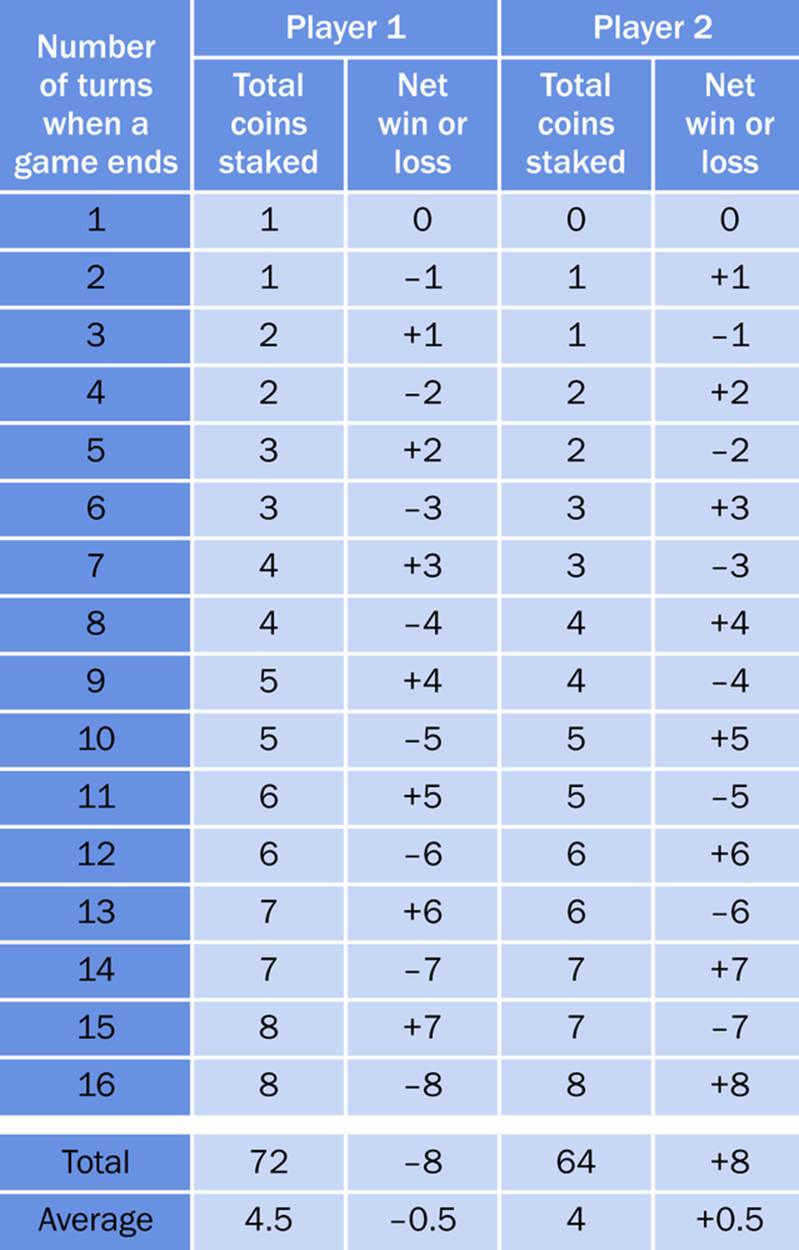
Figure 21-11. This table shows the winnings and losses for each player, in games that end with 1 through 16 turns, and on an averaged basis. On average, the second player will win half a coin per game.
The extra two lines at the end of the table sum each column of numbers and then divide by 16 to find the average for each player, per game. Remember, it’s equally likely for a game to last for one turn, sixteen turns, or any number in between. Therefore, the average will tell us accurately how much each player can expect to win or lose in an average game.
Here’s the bottom line: Player 1 loses half a coin per game, while Player 2 wins half a coin per game—on average.
Understanding the Odds
The reason behind this strange outcome is that Player 1 has a disadvantage when he goes first: he risks a stake in the game before Player 2 risks any of his coins. This disadvantage continues each time Player 1 takes a turn. He’s always risking another coin before his opponent risks one of his. Consequently, as you see in the table, when an average game ends, Player 1’s average stake has been 4.5 coins, while Player 2’s average stake has been only 4 coins.
Because Player 2 wins eight coins for every 64 coins that he bets, he can expect a profit on his investment of 8 / 64 = 0.125, or 12.5%. This may be comparable to the odds on a Las Vegas slot machine, and is more than twice as much as a casino will make from roulette, where it pays out 36 / 38 = 95% of the money placed by bettors, and therefore takes 5%. (Actually the calculation is a little more complicated, as most casinos pay different odds when 0 and 00 come up in roulette, but the percentages are close enough.)
Personally I never play games of chance, because as this game illustrates, the odds are seldom in favor of a player. No matter how lucky you think you are, the mathematics of probability will always beat you in the end.
Suppose you didn’t know anything about the Hot Slot game, and a friend invited you to play it. Suppose your friend said, “Since you’re a beginner, I’ll let you go first.” What a nice guy! He sounds as if he’s doing you a favor. After all, you’ll have the first opportunity to find the Hot Slot. But actually it’s a disadvantage, as we’ve seen. Evidently he is not such a good friend after all.
Would it be worthwhile for someone to try to make money by playing the Hot Slot game? Suppose two people are playing with pennies, and each person starts with 100 pennies. Because Player 2 wins an average of half a penny per game, he or she would hope to win all of Player 1’s money within 200 games.
That sounds time-consuming. Suppose it takes two seconds for each person to place a coin, and ten seconds to remove coins from the slots and reset the system for the next game. Since a game will be completed in eight turns on average, it will last for slightly less than 30 seconds. Therefore 200 games will take 1 hour 40 minutes. That’s a lot of time, just to win $1.
However, if the stakes were quarters instead of pennies, Player 2 could hope to make about $15 per hour. And if the players were using tokens with a value of, say, $1 each, Player 2 would be expecting to rake in $60 of his opponent’s money per hour. (Of course, he would have to persuade the opponent to make the first move in every game.)
Once again, the message is clear: before gambling, do the math!
Background: Alternative Game Arrays
If Player 2 has a 12.5% advantage in a sixteen-coin game, would it be the same in a game with fewer or additional coins and slots?
No, the advantage will be different. To see why, I’ll take an extreme example. Suppose we have a game in which there are only two slots. In this game, the person who goes first gets his own coin back if he wins and loses it if the second player wins. So the first player never wins anything! On average he will win half the games and lose half the games, so in an average game, he should expect to lose half a coin, while Player 2 should expect to win half a coin.
In fact, no matter how many coins and slots there are (so long as it’s an even number), Player 1 always loses an average of half a coin per game, and Player 2 always wins an average of half a coin per game. Extra coins and slots simply mean that each game lasts longer, and Player 2 has to put up a higher stake, to win that half a coin.
Extra coins and slots help to hide the fact that Player 2 has an advantage. In a two-slot game, the advantage becomes obvious. In a sixteen-slot game, it’s not obvious at all.
And a Microcontroller?
Yes, a microcontroller could run this game, but I don’t think it would be any simpler. Your microcontroller probably would have fewer than 16 outputs to activate a Hot Slot. You could use just four outputs to provide a binary code from 0000 through 1111, but then you’d still need a decoder, analog multiplexer, or demultiplexer.
Bearing in mind the additional cost of the microcontroller, and the additional time involved in writing the program code, I think this is one experiment where discrete components are simpler.
All materials on the site are licensed Creative Commons Attribution-Sharealike 3.0 Unported CC BY-SA 3.0 & GNU Free Documentation License (GFDL)
If you are the copyright holder of any material contained on our site and intend to remove it, please contact our site administrator for approval.
© 2016-2026 All site design rights belong to S.Y.A.