Make: More Electronics (2014)
Chapter 29. Experiment 29: Common Sensors
In this and the next five experiments, I’m going to be discussing sensors. This is an exciting field, because it’s still developing rapidly. While basic designs and capabilities of the logic chips that I’ve been using were established long ago, the evolution of affordable sensors is proceeding all around us.
The key word, here, is “affordable.” To take one example, in the year 2000, perhaps I could have bought an accelerometer, if I had shopped around—although I might have had difficulty finding a distributor that would sell me just one, and it would have been expensive. Moreover, after I bought it, I could have had some problems figuring out exactly how to use it.
Today, in the United States, I can buy a three-axis accelerometer from Hong Kong for $3, with free international shipping, and it will plug right in to an Arduino microcontroller.
The evolution of handheld devices has encouraged the mass production of sensors that are small, reliable, easy to use, and cheap. A modern smart phone may contain as many as ten different sensors, including a microphone, touch screen, wireless antenna, GPS, ambient light sensor (to adjust screen brightness), accelerometer (so that it knows which way up you are holding it), thermometer, barometer, hygrometer—and a proximity sensor so that when you raise the phone to your ear, it senses the nearness of your head and turns off its display to ignore touch inputs and save power.
The field of sensors is now so extensive, I don’t have space to describe more than a few. Use the search term “sensor” on sites such as http://www.jameco.com and http://www.sparkfun.com, and you’ll be surprised by what you find.
The Little Magnetic Switch
Perhaps the oldest sensor of all is the humble reed switch. I mentioned it briefly in Make: Electronics, but only regarding its application in alarm systems, where it is packaged in a small white plastic module to sense if a window or a door has been opened. I’ll go into more detail here.
Let’s get acquainted with some samples of this helpful little device. Two reed switches are shown in Figure 29-1.
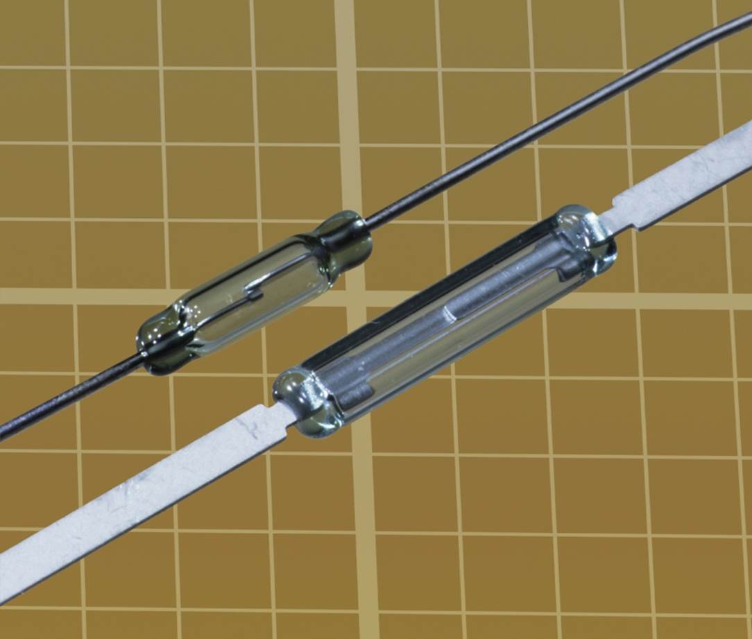
Figure 29-1. Reed switches. Note that each square in the graph-paper background is 0.1” x 0.1”.
The glass capsules contain an inert gas to protect the contacts from oxidation. This is a nice feature, but the glass is so thin and fragile, it can break if you merely bend the leads too sharply. You really have to handle reed switches with care. If you need a more rugged package, some switches are sealed in plastic, as shown in Figure 29-2.
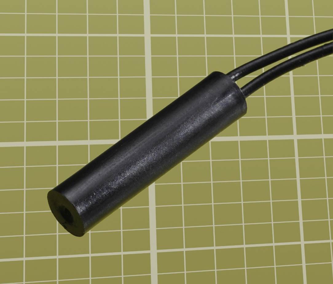
Figure 29-2. Some reed switches, such as this one, are encapsulated in plastic to provide some protection.
Reed Test
The following experiment is going to be the simplest in the book—even simpler than the glue-operated transistor in Experiment 1.
While there is no standardized schematic symbol for a reed switch, it is often depicted as in Figure 29-3. Connect it as shown, and bring a small bar magnet near it. The magenta and cyan color bands indicate the poles of the magnet.
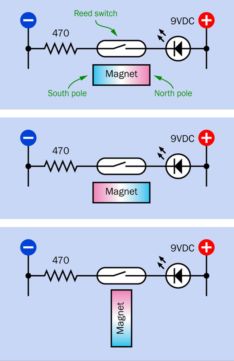
Figure 29-3. Testing a reed switch.
You should find that the switch will be about equally sensitive in the top and middle versions of this figure. It will be least sensitive when one pole of the magnet is much closer to it than the other, as in the bottom section. This is important information if you want a reed switch to give a reliable response.
§ Even though it’s called a reed “switch,” it behaves like a pushbutton. It only stays on while it is exposed to a magnetic field. When the magnet moves away, it turns off.
How It Works
The contacts inside the switch are mounted on flexible metal strips (the “reeds”), which are not magnetized but are magnetically conductive. Bear in mind that a magnet creates a field that induces magnetism in other objects. In fact, when a magnet pulls a piece of iron toward it, the nearest pole of the magnet creates a temporary, opposite pole in the iron.
If a magnet is aligned parallel with the switch, the reeds become temporarily magnetized with opposing polarities. This creates a force of mutual attraction, causing the reeds to bend toward each other and create a connection. When the magnet is withdrawn, the reeds spring apart.
The reason the switch is almost equally sensitive with the magnet oriented in the top and center sections of Figure 29-3 is that the reeds become magnetized relative to each other in each case. Even though the field is reversed, they still attract each other.
Level Sensor
A few years ago, when I was building a prototype of a rapid-cooling device for a research lab, I needed a liquid-level sensor. The most basic type is an on-or-off device called a float switch that detects when liquid has reached a maximum or minimum level. A cylindrical float made of closed-cell plastic foam rests in the surface of the liquid. The float has a hole in the middle, like a donut, allowing it to slide freely up and down a plastic rod containing a reed switch. The switch is closed by a magnet mounted inside the float.Figure 29-4 shows a low-cost sensor of this type.
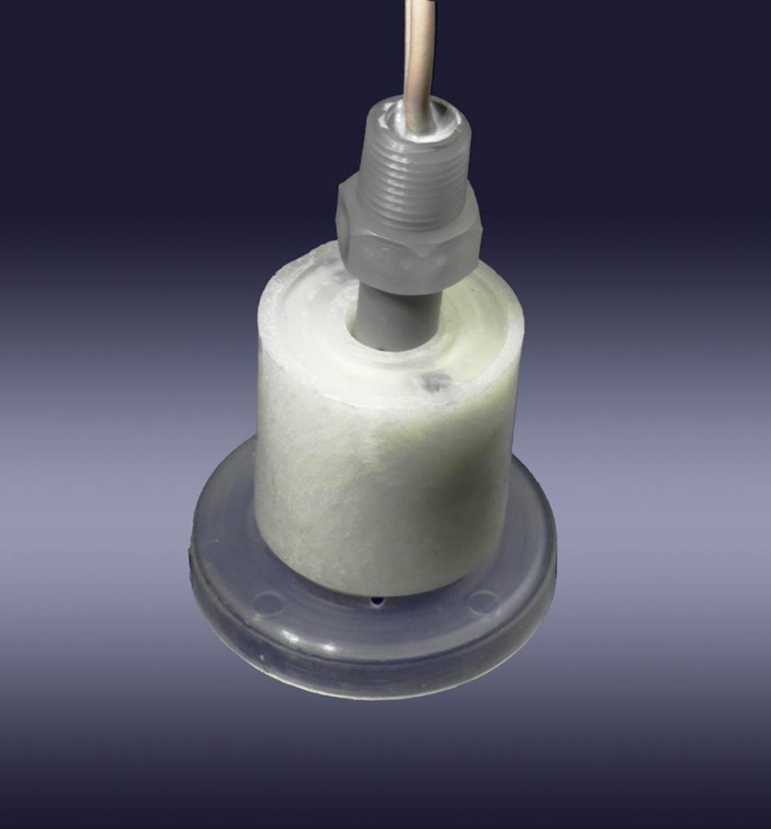
Figure 29-4. A simple, low-cost level sensor in which a magnet inside the float activates a reed switch in the central plastic rod.
Perhaps you can think of some applications. For instance, despite many decades of refinement, the shutoff valves inside toilet tanks are still not entirely reliable. Where I live, in the high-desert wilderness, water is a valuable commodity, and a malfunctioning toilet tank is not a trivial matter. Maybe I should mount a float switch inside the toilet tank, with wires leading out to an LED and a 9V battery. Then if the shutoff valve starts to fail and the water level rises up to the overflow, the LED will warn me. Alternatively, I could use a small beeper.
Here’s another possibility. Some people live in houses where the basement is vulnerable to flooding. That’s another situation where you could locate a float switch. What other uses could you imagine?
Fuel Gauge
In some applications it’s useful to have a level sensor that varies its output in proportion with the volume of liquid, instead of just giving an on-or-off output. This would be commonly used as a fuel gauge.
The traditional way of doing this is with a float mounted on an arm, which rotates the wiper of a potentiometer. For decades, cars used this system in their gas tanks—but it’s bulky, not very accurate, and vulnerable to dirt and moisture if you use it outside of a sealed environment.
While looking for a better way to measure a liquid level, I ran across a fuel-level sensor on eBay that consisted of just an eight-inch metal rod with a float that would slide up and down it. I couldn’t figure out how it worked, so I ordered one. When I received it, I sawed the end off the rod and discovered that it was actually a hollow tube. Inside was a very narrow circuit board, about a quarter inch wide. Mounted at intervals along the board were seven reed switches and six resistors.
At first, I was puzzled. How could the reed switches be magnetically triggered, when they were enclosed in a steel tube? Then I realized that the tube was made of stainless steel, which is nonmagnetic. The field from a magnet mounted in the movable float had no trouble penetrating to the switches.
As the float moved up and down, its field closed one switch after another, and since the resistors were wired in series, they functioned as a voltage divider tapped at six locations. This enabled a terminal at the top of the assembly to detect a varying total resistance. A simplified version of this fuel-level sensor is shown in Figure 29-5, with just four resistors and five reed switches.
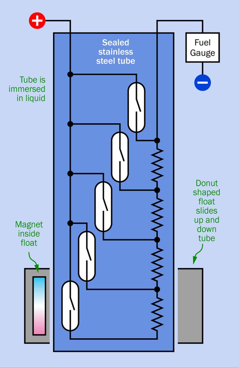
Figure 29-5. A liquid-level sensor using reed switches and resistors that form a multistage voltage divider.
Of course, the resistance in this type of sensor does not vary gradually, but apparently seven steps are considered acceptable for a fuel gauge in a car.
I mention this to give you an idea of the versatile way in which a sensor as simple as a reed switch can be used. Incidentally, I believe that many automotive fuel sensors still rely on a similar system, except that it now uses Hall-effect sensors instead of reed switches. I’m going to get to Hall sensors in Experiment 30.
Quick Facts About Reed Switches
§ Most reed switches are SPST with contacts that are normally open. A few have normally-closed contacts. Either way, a reed switch behaves like a pushbutton, with a magnet providing the “push.”
§ SPDT and DPDT reed switches are available. Figure 29-6 shows a single-pole, double-throw reed switch. The pole of the switch is connected to the single wire at one end. The longer of the two wires at the other end is connected with the contact that is normally closed.
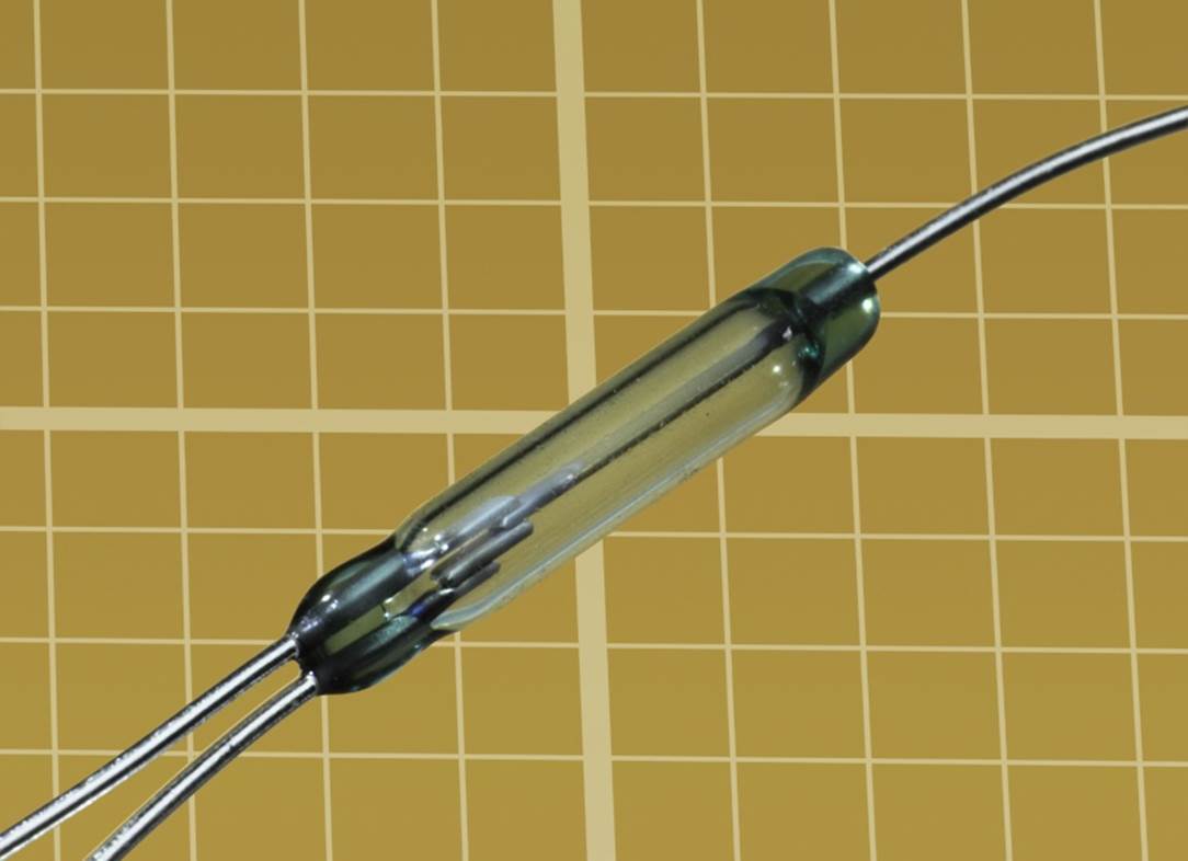
Figure 29-6. A single-pole, double-throw reed switch.
§ A reed switch works regardless of the polarity of the magnetic field, because the field induces opposing magnetic poles in the reeds.
§ Some types of very small relay contain a reed switch with a coil wrapped around it. When the coil is energized, it functions as an electromagnet and closes the switch.
§ Reed switches naturally display some hysteresis. The force required to begin closing the contacts is greater than the force required to keep the contacts closed. Therefore the magnet that closes the switch can be withdrawn slightly before the switch will reopen.
Reed switches have obvious limitations:
§ A reed switch is typically enclosed in a thin-walled glass capsule, which cracks or shatters easily.
§ The tiny contacts will quickly deteriorate if you try to switch too much current.
§ Contacts may break if they are subjected to excessive vibration. Always try to avoid dropping a reed switch, especially onto a concrete floor.
§ Although reed switches are designed to be durable, they can never be quite as reliable as solid-state switches (no matter what the manufacturers may claim).
§ The switch can be accidentally triggered by stray magnetic fields.
§ It may fail to be triggered if the magnet is not oriented correctly.
§ When the contacts of a reed switch close, the impact causes “reed vibration,” also known as contact bounce. This is a greater problem in larger switches where contacts have greater momentum. Contact bounce can be misinterpreted by digital components as multiple closures of the switch.
However, reed switches have some advantages compared with solid-state sensors:
§ No external power supply needed.
§ No power consumption, either when the switch is opened or when it is closed.
§ No interfacing components, amplifier, or similar circuitry needed.
§ Negligible current leakage when the contacts are open.
§ Negligible resistance when the contacts are closed.
§ Higher-voltage versions are available.
§ Higher-amperage versions are available.
§ Can switch AC or DC.
§ Less vulnerable to electrostatic discharge.
§ Not significantly affected by ambient temperature.
Easy Substitution
Generally, you can use a reed switch anywhere in a circuit where you have used a SPST switch. For instance, reed switches are commonly substituted for snap-action limit switches to stop a motor when it reaches the limit of its rotation.
You could substitute sixteen reed switches for the sixteen pairs of coin contacts that I described for the Hot Slot game in Experiment 21. The rest of the circuit wouldn’t have to be modified at all. The only problem, of course, is that you wouldn’t be able to play that game with coins anymore. You would need sixteen disc-shaped magnets.
I think there’s a better way to add sensors to that game, allowing the continuing use of coins. I’ll get to it in Experiment 31, when I deal with optical sensors (see Chapter 31).
Installing a Reed Switch
Reed switches are available with differing sensitivity. The samples I have used can be activated by a tiny neodymium magnet measuring about 1/8” × 1/4” × 1/16”. So long as the magnetic axis is parallel with the switch, the switch will work when the magnet is still half an inch away.
Miniature magnets and small reed switches provide a lot of flexibility in the way that you use them. For instance, a switch can be glued in place, and the magnet can be hidden behind a thin layer of plastic.
For most of the projects in this book, you could build a small box that seems to switch itself on when you open the lid. Note that the switch would not draw any power, either while the lid was open or closed.
Reed switches can also be used to provide security in a car or home. You could mount a small magnet on your key ring (so long as it remains safely separate from your credit cards) and use it to activate a hidden reed switch connected with a latching relay, to switch off an alarm system before you enter.
Another possibility is to mount a magnet in a small pointer or stylus, as the input device in a game.
Background: Magnetic Polarity
I’m going to describe some aspects of magnets, because magnets are required to trigger switches and Hall-effect sensors (coming up shortly).
A permanent magnet always has two poles, which we refer to traditionally as “north” and “south.” Perhaps you are thinking that these must be similar to the north and south poles of planet Earth—in which case, let me just mention that the north pole of a magnet was originally known as the “north-seeking” pole.
Didn’t you learn, somewhere or other, that opposite poles attract? Indeed, if you have two magnets, the north pole of one will be attracted to the south pole of the other. So how can the north-seeking pole of magnet point toward the North Pole of the Earth? The answer is that the Earth’s so-called north pole actually has south-pole polarity.
It would be much too confusing to rename the North Pole as the South Pole at this time, so we’re stuck with a North Pole that isn’t really a north pole at all.
Magnetic Types and Sources
Neodymium magnets were developed in the 1980s and are far more powerful than the old iron magnets that preceded them. Inside any small, modern DC motor, most likely you’ll find neodymium. In fact, neodymium has enabled the miniaturization of devices from cameras to lightweight power tools.
It’s fun to play with powerful magnets, but most reed switches are so sensitive, cheaper iron magnets are sufficient. You can find many sources online. There are always some magnets for sale in assortments on eBay.
Bear in mind that it is actually disadvantageous to use a magnet that is more powerful than necessary, as it can affect other adjacent switches or components.
The most familiar style of magnet is perhaps the bar type, with a square or rectangular cross-section. Usually, but not always, the poles are at oppposite ends of the bar.
Some suppliers (including my favorite source, K&J Magnetics) list the magnetized dimension last. Thus, if a magnet is listed as measuring 1/4” x 3/4” x 1”, the poles are probably at each end of the 1” dimension. But if the magnet is listed as measuring 3/4” x 1” x 1/4”, each flat face of the magnet can have a polarity opposite to the other. Check carefully before ordering!
Magnetic Shapes
A classic horse-shoe magnet is a bar magnet that has been bent into a U-shape, like a horse shoe, so that the two poles are located side by side. This increases the lifting power of the magnet, because the power is greatest where the lines of force between the poles are shortest.
Some sample magnets are shown in Figure 29-7. The dull gray one is iron, while the others are neodymium. All the magnets are holding onto each other, because there was no easy way to keep them apart for the photograph. The little disc-shaped magnet is in two pieces because it broke when it was grabbed by a larger magnet. Bear this in mind: neodymium magnets are brittle.
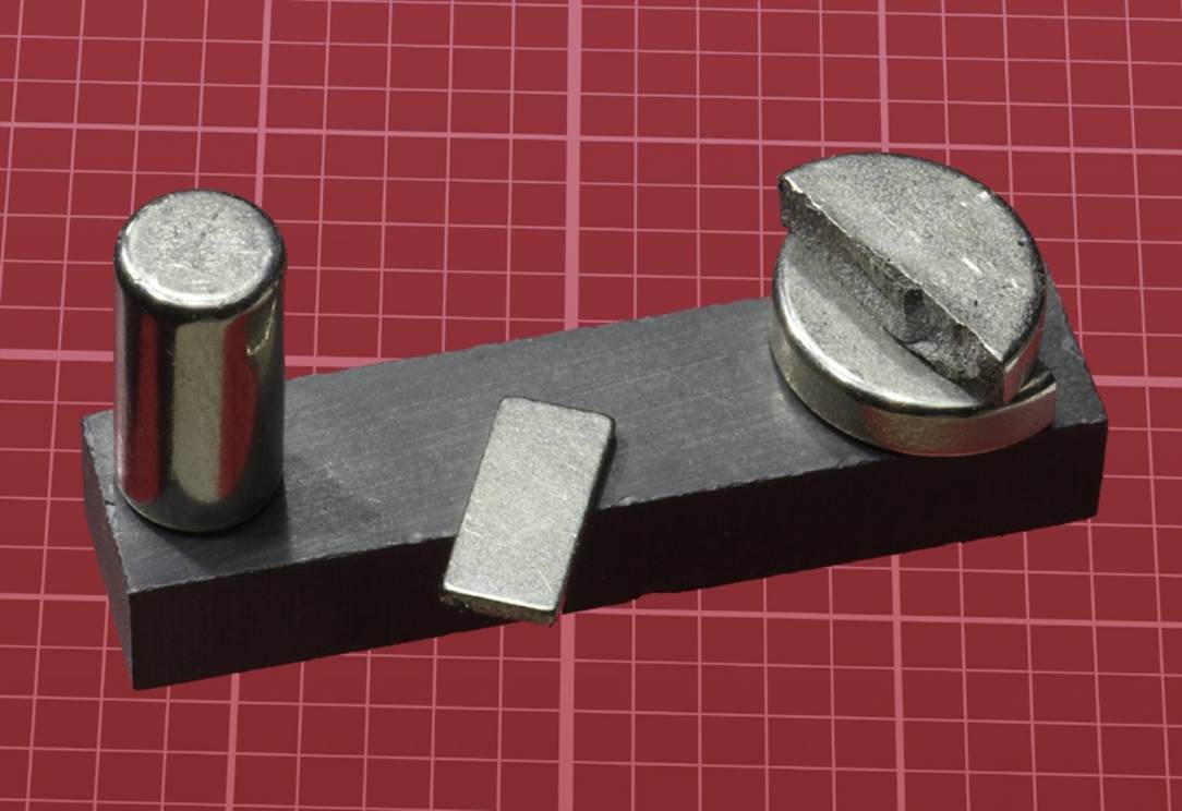
Figure 29-7. A selection of magnets (one of which broke when it was grabbed by another). The dull gray magnet is iron; the others are neodymium.
Discs, cylinders, and ring-shaped magnets are likely to be “axially magnetized.” The axis of a cylindrical magnet is an imaginary line running through the center, as shown in Figure 29-8. You can think of the cylinder as rotating symmetrically around that line. If it is axially magnetized, the opposite ends of its axis have opposite polarity. One flat face of the cylinder contains the north pole, while the other has the south pole—as in the rendering in Figure 29-9, where red and blue indicate opposite poles.
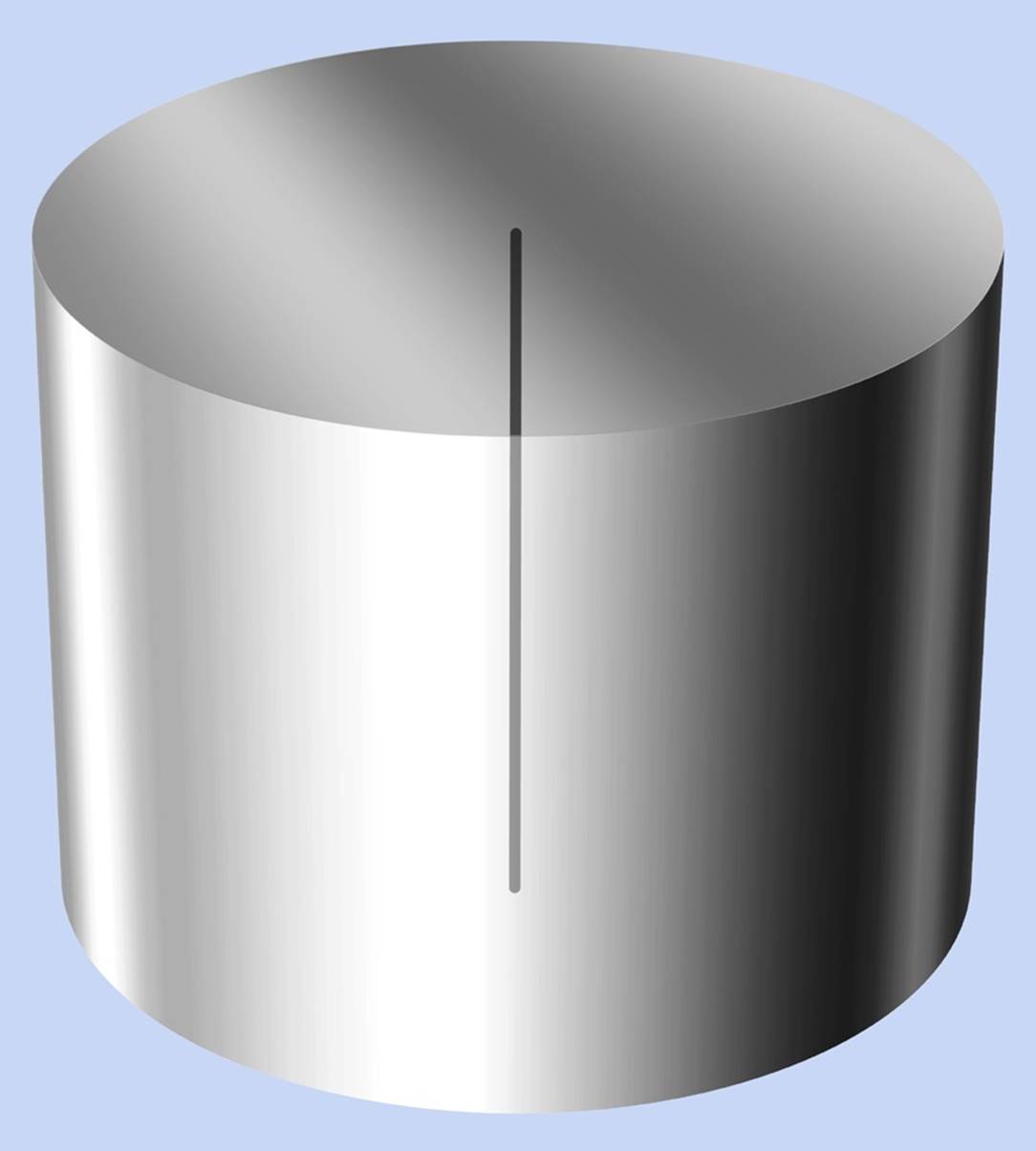
Figure 29-8. The imaginary line running through the center of the cylinder is its axis.
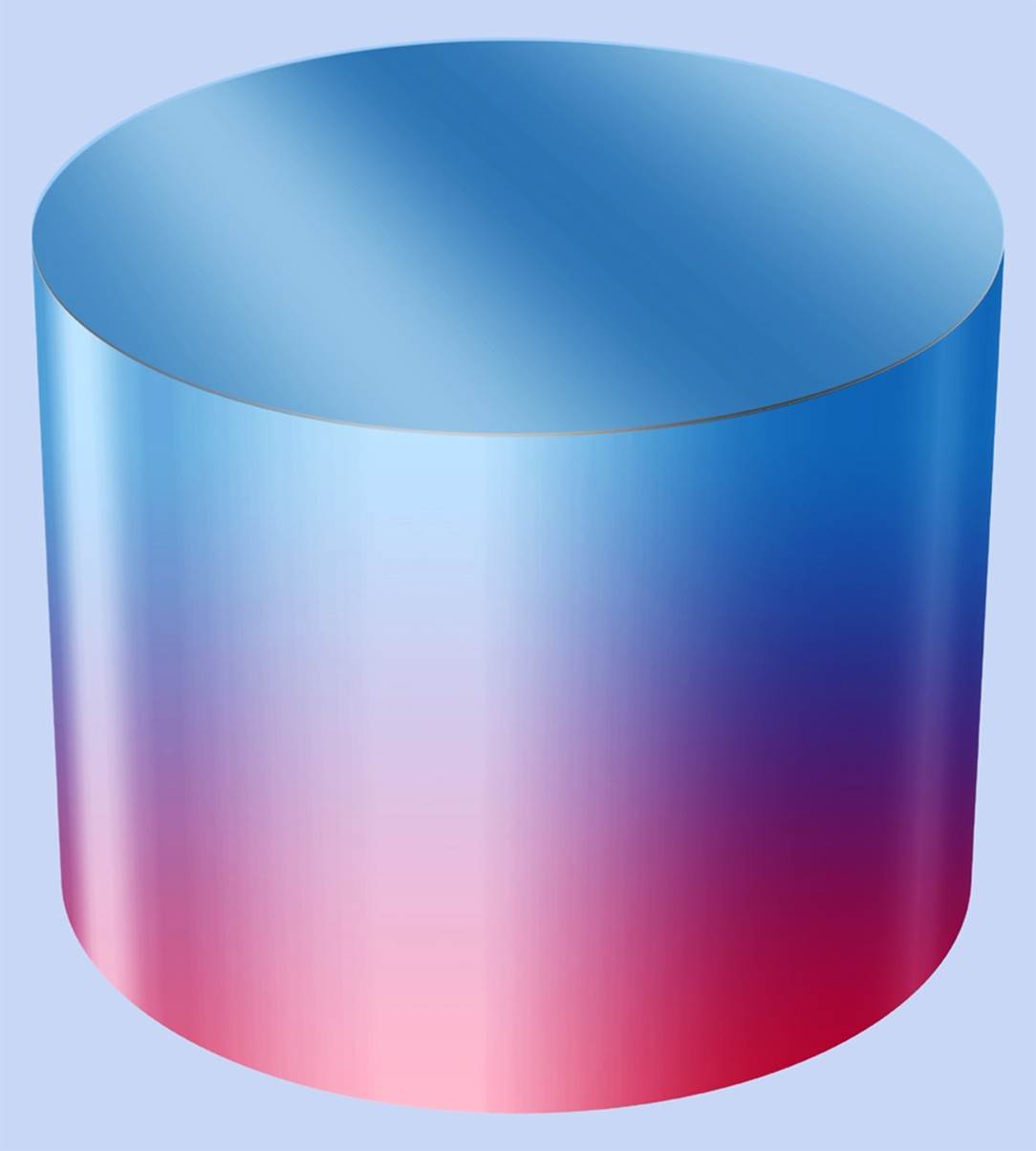
Figure 29-9. An axially magnetized cylindrical magnet has its poles at opposite ends of its axis.
Most round magnets are axially magnetized, including ring magnets. Figure 29-10 shows a classic demonstration in which alternate ring magnets are turned over so that north poles are opposite north poles, and south poles are opposite south poles, creating opposing forces. The magnets in this photograph are not stuck to the central rod in any way; they can slide freely.
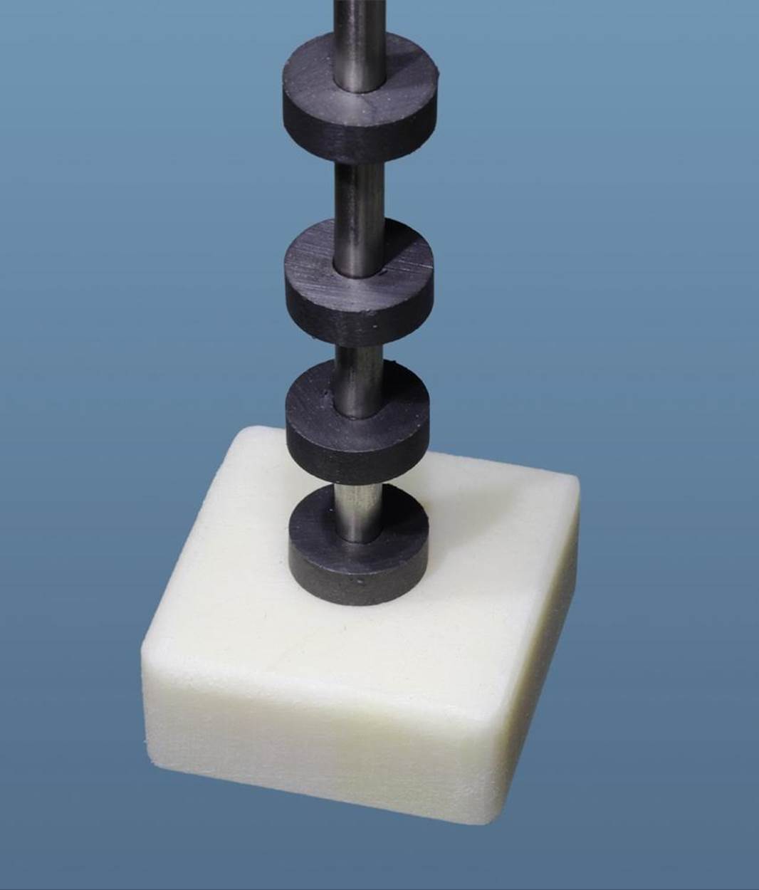
Figure 29-10. Most ring magnets are axially magnetized. You can stack them on a nonmagnetic rod (stainless steel, in this photograph) with their similar poles facing each other, so that the rings force each other apart.
The cumulative weight of the rings pushes them closer together at the bottom end of the rod. If you exert additional force with your finger, you can push the rings together, but they jump apart as soon as you let go. In fact, in this little demo, the topmost magnet will jump right off the top of the rod.
I never get tired of this elementary demonstration of magnetic force. Where does the energy come from to make the magnets behave this way? The answer, of course, is that it comes from you, when you push them together. Magnets do not create energy; they merely store it.
Some circular magnets are radially magnetized, but they are a small minority. Figure 29-11 suggests this concept. One curved side of the cylinder has a polarity opposite to the other side.

Figure 29-11. A radially magnetized cylinder has its poles on its opposite curved sides.
To determine the polarity of a magnet, it helps to have two of them. Observe their orientation as they attract or repel each other. If two circular magnets are axially magnetized, the force between them will not change when they are placed face to face and one magnet is rotated around its axis relative to another.
Make Even More: Eddy Currents
One of the most surprising attributes of a magnet is that it can interact with nonmagnetic metals such as aluminum. If you take a neodymium ball magnet and drop it into a vertical aluminum tube that is just slightly larger than the ball, the magnet will drift slowly down as if it is falling through molasses. The thicker the aluminum is, the more slowly the ball will fall. Thus, a tube with walls that are 1/8” thick will be much more effective than one with walls that are 1/16” thick. The same effect can be demonstrated with a copper tube.
Figure 29-12 is of a ball magnet in a tube where a slot has been cut to reveal the ball. It takes about a second to drift down from one end of the 12” tube to the other. This is a graphic demonstration of the interaction between magnets and metals.
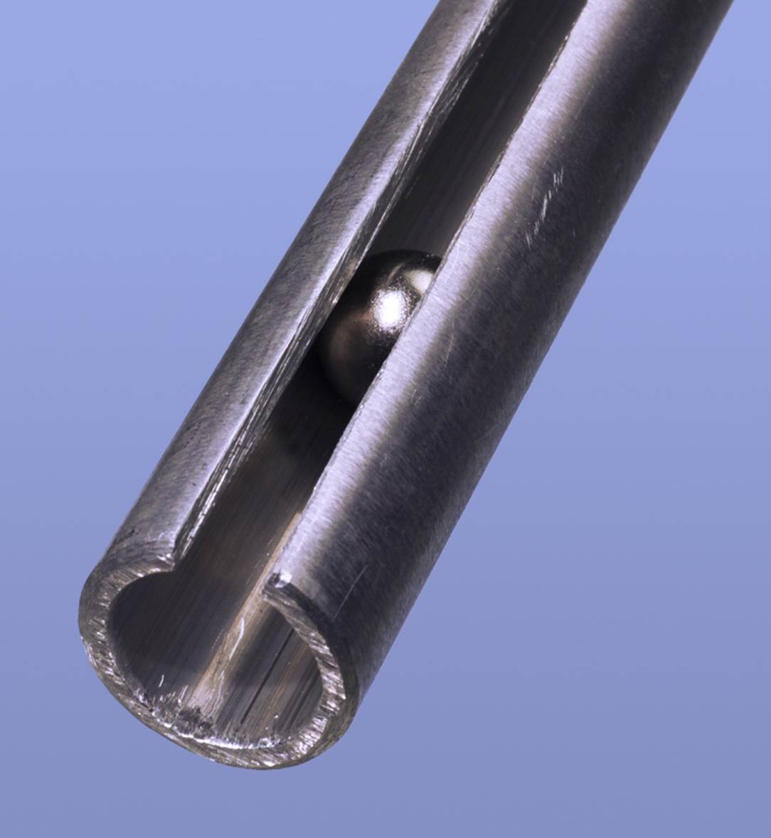
Figure 29-12. A neodymium ball magnet is powerful enough to generate electrical eddy currents when it moves close to a nonmagnetic but electrically conductive metal, such as aluminum or copper. Generating the eddy currents requires energy, causing the ball to fall very slowly.
The reason for this strange effect is that a moving magnet induces electric “eddy currents” around it in a nearby electrical conductor, such as aluminum or copper. In fact, this is how most electricity is generated in the world: by moving copper windings through magnetic fields. (Solar cells are the exception to this rule.)
If you’re wondering what happens to the eddy currents that are generated, they create a tiny amount of heat—as is always the case when electricity flows through a conductor. In this way, the experiment demonstrates the principle of conservation of energy.
The demo could be enhanced by mounting a series of reed switches at the back side of the tube, in conjunction with resistors in series, as in the gas-tank gauge that I mentioned previously. If the resistors are put in a circuit between the discharge and threshold pins of a 555 timer running in astable mode at an audible frequency, the falling ball will create an ascending series of tones as it passes the switches.
This demonstration will also work if you use aluminum with an angle-shaped or channel-shaped cross section, although the ball won’t fall quite so slowly.
Warning: Magnetic Hazards
I would be irresponsible if I didn’t include a note of caution. You may find it hard to believe that you could be injured by a magnet, but neodymium magnets are quite capable of hurting you, as I have learned myself the hard way.
An N52-grade cylindrical neodymium magnet measuring only 3/4” in diameter and 3/4” tall can be rated to lift a weight of around 40 lbs. That’s the weight of five gallons of water. If you have two of these magnets with opposing poles facing each other, the force between them will be doubled, and if they slam together with one of your fingers in the way, at the very least, you’re going to end up with a blood blister.
You will run a different kind of risk when you try to separate the magnets afterward. Expect some torn fingernails and a lot of exasperation. You’ll find some good YouTube videos online, showing how to deal with powerful magnets.
Neodymium is brittle, and although the magnets are nickel plated, they can still chip unexpectedly as a result of hard impacts caused by magnetic attraction. The metal chips are very sharp and can fly at high speed. You should wear eye protection if you start playing with heavy-duty magnets.
It should be obvious (but I’ll mention it anyway) that you must keep strong magnets away from hard drives and other magnetic storage media, including credit cards. In fact, magnets should be stored at a safe distance from all electronic devices.
Lastly, a pacemaker can be affected by a strong magnetic field. Use powerful magnets with appropriate caution.
All materials on the site are licensed Creative Commons Attribution-Sharealike 3.0 Unported CC BY-SA 3.0 & GNU Free Documentation License (GFDL)
If you are the copyright holder of any material contained on our site and intend to remove it, please contact our site administrator for approval.
© 2016-2026 All site design rights belong to S.Y.A.