Make: More Electronics (2014)
Chapter 30. Experiment 30: Hidden Detectors
Hall-effect sensors are all around you. When you close the lid of your laptop, probably a Hall sensor under the plastic skin of the case detects the action and puts the computer into sleep mode. When you switch on your pocket camera, a Hall sensor detects that the lens is fully extended. Hall sensors are inside your hard drive, detecting the rotation of its motor and controlling its speed. They’re in the electronic ignition of your car—and in the car’s door lock, which switches on the interior light when your key turns. Your modern washing machine may use a Hall sensor to determine if the door is closed. Similarly, your microwave oven.
Each sensor generates a tiny electric current in response to a magnetic field. It can be used like a reed switch, but is totally solid state. The principle of operation was discovered in 1879, but the effect was so small, widespread application was impractical until the development of integrated circuit chips that could contain amplifiers in addition to the sensors.
The great advantages of Hall sensors are cheapness, reliability, and miniaturization—unlike reed switches, they can be tiny surface-mount devices. They have a very fast response time, they’re difficult to damage, and they are made in four types that have differing behavior to match your particular application. Integrating them into a circuit requires a little extra trouble, but they are a versatile alternative to reed switches.
A selection of Hall-effect sensors is shown in Figure 30-1.
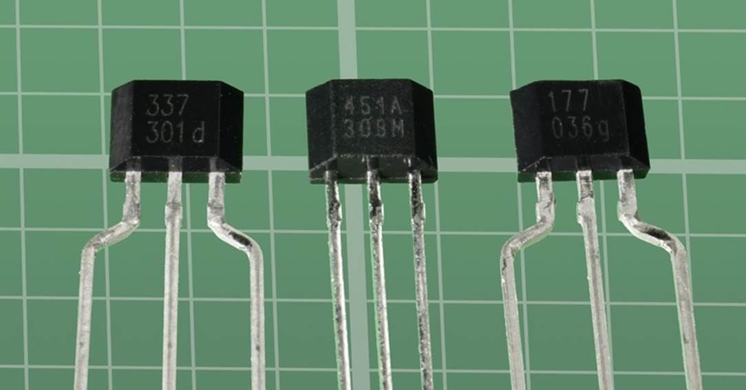
Figure 30-1. A variety of Hall-effect sensors.
Hall Test
This test will use the most common and cheapest type of Hall sensor, which is “bipolar,” meaning that one magnetic pole will switch it on while the opposite magnetic pole is required to switch it off. (In this usage, the term “bipolar” has nothing to do with bipolar transistors.) A bipolar sensor is also referred to as “latching,” since it stays in one state until you force it back to the other state.
Figure 30-2 shows a simplified view of an ATS177 sensor made by Diodes Incorporated. Most Hall sensors have the same pinouts. The code below the part number usually relates to the date of manufacture and is not relevant to us here.
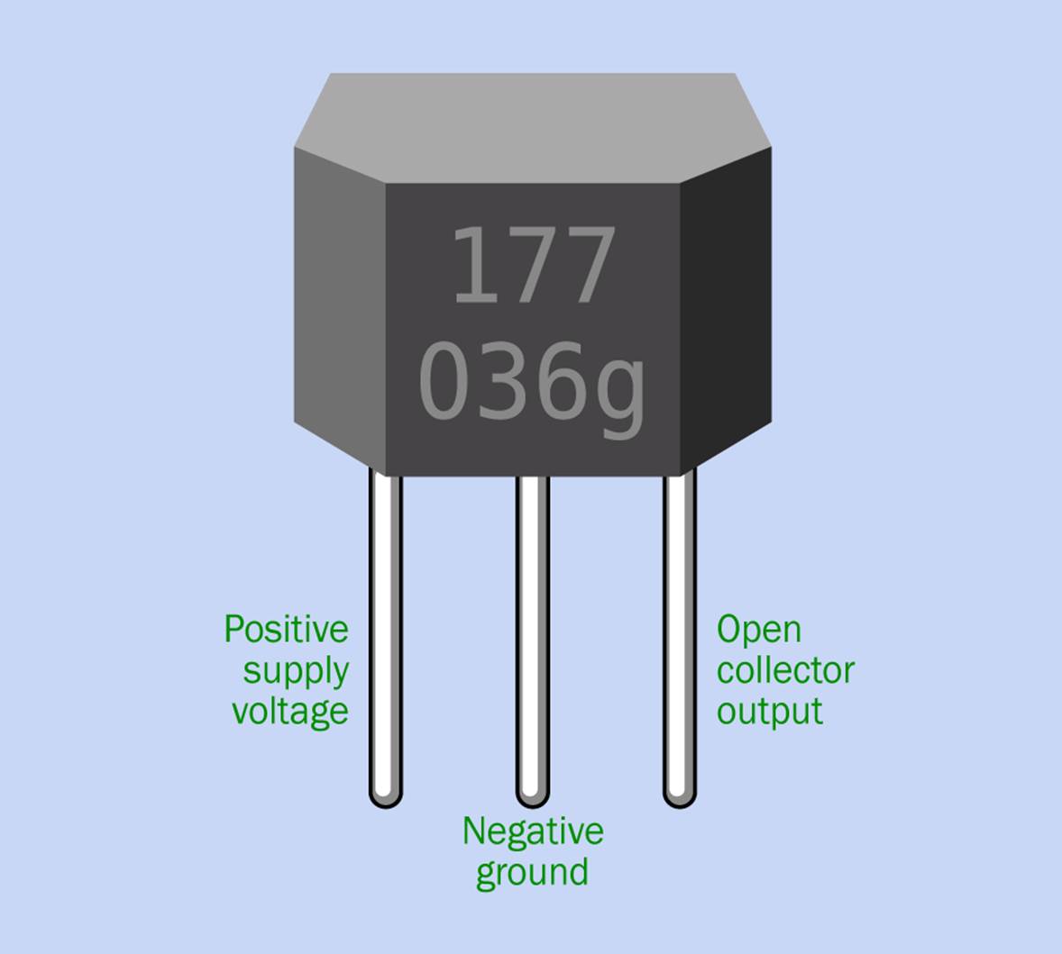
Figure 30-2. Pin functions for an ATS177 bipolar Hall-effect sensor made by Diodes Incorporated. Other Hall-effect sensors usually have the same pin functions.
In a datasheet, the positive power-supply pin will be identified as Vcc or Vdd (which mean the same thing, in this case). Negative ground is almost always identified as Gnd. The output is often identified as Out, but in the case of sensors that are intended for connection with logic chips, DO may be used instead, meaning Digital Output.
A sensor is most easily tested with the same kind of rectangular bar magnet that you used to investigate a reed switch in Experiment 28. However, unlike a reed switch, a Hall sensor is designed to be activated when one pole of a magnet is much closer to it than the other pole.
Assemble the schematic shown in Figure 30-3. Note that the sensor has an open-collector output, just like the phototransistor, the electret microphone, and the comparator that you have encountered previously. If you need to remember how this works, see The Output.
I’m suggesting a 9VDC power supply so that you can use a 9V battery. The supply doesn’t need to be regulated, because this sensor is not a digital device. Most Hall sensors can use up to 20VDC without any trouble, but a few are designed for lower voltages. Always check the datasheet to be sure.
Apply the magnet as shown in Figure 30-4. Because the poles of a bar magnet are not usually marked, you’ll have to use trial and error to find which end of the magnet switches the LED on. Once the LED is on, use the opposite end of the magnet to switch it off.
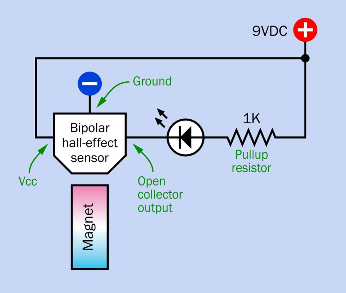
Figure 30-3. A very simple schematic for investigating Hall-effect sensors.
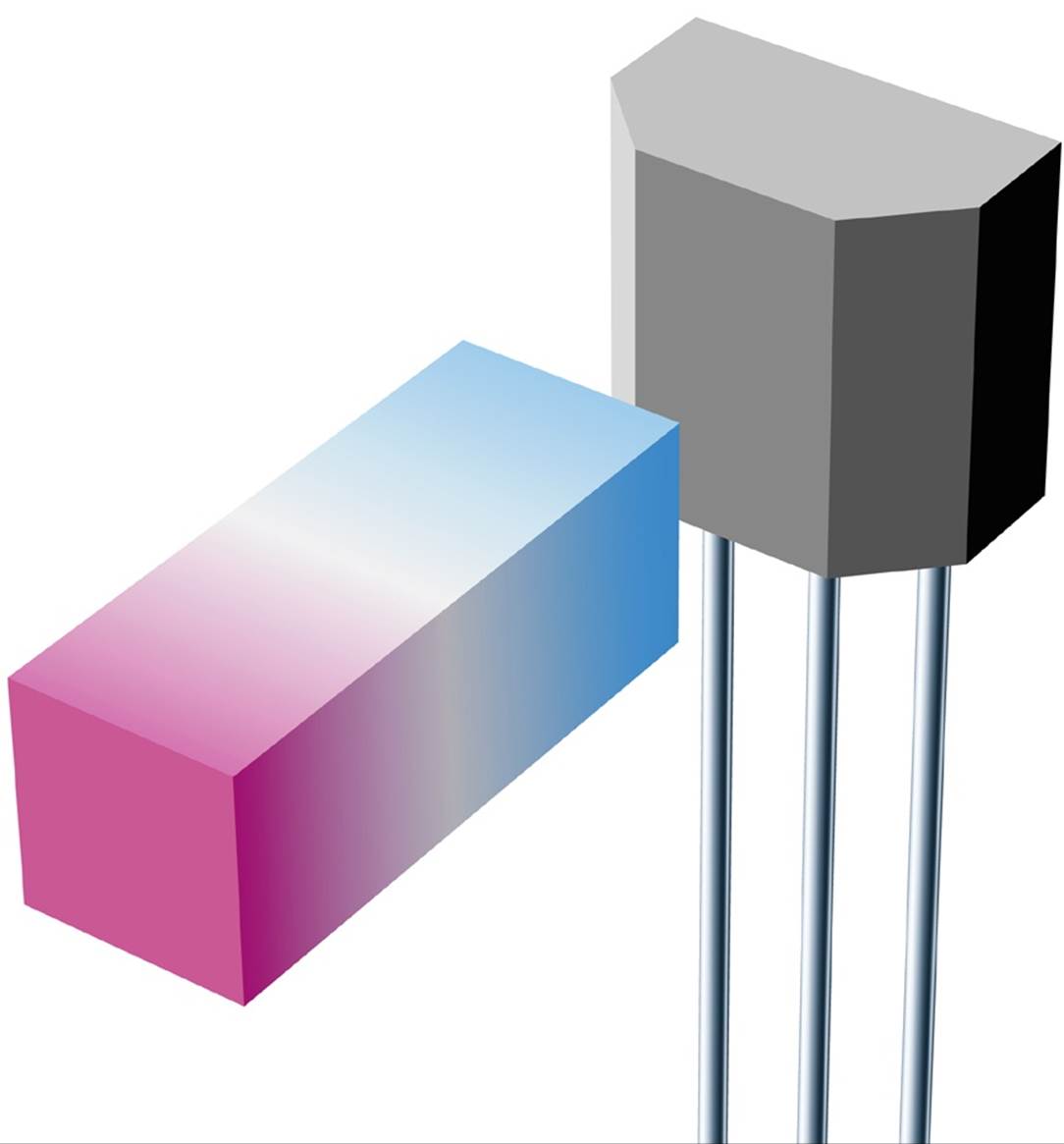
Figure 30-4. Apply one pole of a magnet to the bevelled face of the bipolar sensor, keeping the other pole farther away. Reverse the magnet to flip the sensor into its opposite state.
The LED should switch on and off cleanly, without any dimming or flickering. This is enabled by circuitry included with the sensor known as a Schmitt trigger.
Typically a Hall sensor can sink up to 20mA, but that will be an absolute maximum value. Using a 1K pullup resistor with a 9VDC supply, you should find that the sensor is sinking about half of that. It’s a good idea to check this with your meter. A typical LED rated for 20mA will not glow brightly when it is only passing 10mA, but certainly should be bright enough for you to see that it makes clean on-and-off transitions.
Applications
You may feel that a bipolar Hall sensor is less convenient than a reed switch, not just because it requires a power supply, but because you have to use one pole of a magnet, and then the other, to switch the sensor on and off. However, the sensor is designed to work conveniently in a situation where a series of poles passes it—or, conversely, where it passes a series of poles.
Pulses from the sensor can be used as feedback to provide precise control of the speed of a motor. The simplified rendering in Figure 30-5 shows this concept, where a rotating object has magnetized teeth with alternating polarity.
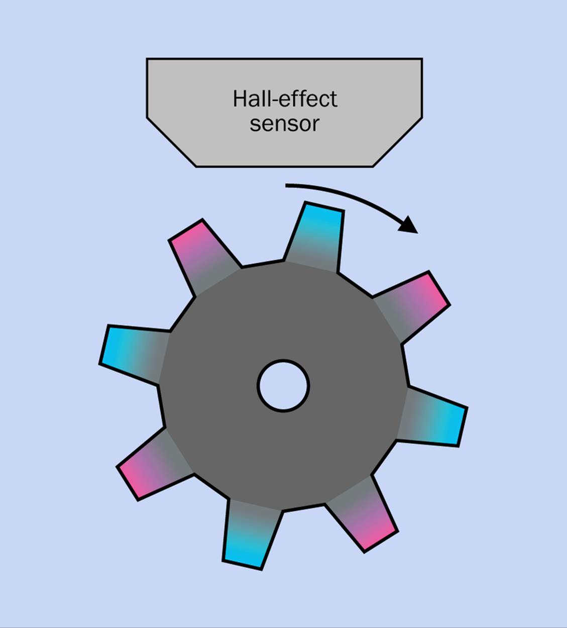
Figure 30-5. A Hall sensor can measure the speed of rotation of wheel with teeth of alternating magnetic polarity.
In your test experiment, try turning your magnet 90 degrees and then slide it past the sensor, so that it is affected by first one pole and then the other. Once again you should see that the LED makes a clean on-off transition—and displays some hysteresis, because the sensor tends to stick in its on and off states.
The hysteresis can be graphed as in Figure 30-6. Compare this diagram to Figure 6-8, illustrating the behavior of a comparator. The difference is that the comparator responds to changes in voltage, while the sensor responds to changes in magnetic field.
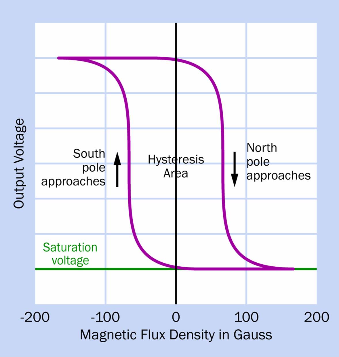
Figure 30-6. The hysteresis of a bipolar Hall sensor.
You could make an odometer or a speedometer for a bicycle by mounting a Hall-effect sensor on one of the forks and attaching a magnet between two spokes in one of the wheels. The output from the sensor would go to a microcontroller that would convert each rotation of the wheel into a distance value. The microcontroller could then calculate speed by dividing distance by time.
Quick Facts About Hall Sensors
§ The through-hole versions of Hall effect sensors are usually sealed in a little piece of black plastic, about 0.1” x 0.1” x 0.05”, with three leads. This is similar to, but smaller than, a generic TO-92 transistor package.
§ When a datasheet refers to the “front” or “top” of a sensor, it means the face that has a part number printed on it. This face has bevelled edges, while the “back” of the sensor does not. Usually the sensor is designed to respond to a magnetic pole that is brought toward its front, bevelled face.
§ The part number is usually abbreviated to three digits. An additional code below the three digits usually refers to the date of manufacture.
§ The power-supply voltage often ranges from around 3VDC to 20VDC, allowing use with a 9V battery. However, some sensors will only tolerate 3VDC to 5.5VDC. Check datasheets carefully!
§ Like a phototransistor, a Hall-effect sensor is very often encapsulated along with an NPN transistor that has an open-collector output. The absolute maximum current that sinks into this output can be 20mA to 25mA.
§ When a pullup resistor is placed between the open-collector output of a Hall sensor and the positive side of the power supply as in Figure 30-3, the output will appear to be low when the sensor is activated and high when it is deactivated.
§ Many Hall sensors also include a Schmitt trigger, which is a circuit that creates a clean on-and-off response with some hysteresis.
§ Different variants of sensor may be activated by either a magnetic south pole or north pole. The datasheet should provide this information.
§ Hall sensors are free from the contact bounce that is a problem in reed switches. This makes them useful for providing an input to a logic gate.
Hall Types
There are four common types of Hall-effect sensors.
The bipolar type has just been described. It requires magnetic fields of opposite polarity to switch it on and off.
A unipolar Hall sensor will switch on in response to proximity with one magnetic pole and will switch off when the magnet is removed. It doesn’t need an opposite magnetic pole to switch it off.
Unipolar sensors are available in versions that are activated either by a magnetic north pole or south pole. Like the bipolar sensor, they use a Schmitt trigger to achieve a clean on-off response.
Remember that in its “off” state, the open-collector output of a Hall sensor has a high resistance between it and negative ground so that the output voltage provided through a pullup resistor will appear to be high. When the sensor goes into its “on” state, the output voltage appears to be low. This is the same behavior you saw with a phototransistor.
A so-called linear Hall sensor does not contain a Schmitt trigger and creates a voltage (amplified by the internal transistor) which varies in proportion with external magnetic field. In the absence of a magnetic field, the output from the sensor is half of its supply voltage. In response to one magnetic pole, the output from the sensor diminishes almost to 0VDC. In response to the other magnetic pole, the output increases almost up to the limit of the supply voltage.
Linear Hall sensors are also known as “analog” sensors. The output pin is usually connected with the emitter of an internal NPN transistor, rather than its collector. A minimum 2.2K resistor must be applied between the output pin and ground to limit the sink current.
The variable output can be interpreted to measure the distance between the sensor and a magnet. The perceived magnetic field decreases with distance, so the sensor will not respond where the distance becomes significant (more than 10mm in most cases).
The omnipolar type of Hall sensor closely resembles a reed switch. It is switched on by a magnetic field of either polarity and switches off in the absence of a magnetic field. This sensor actually contains two Hall detectors and a logic component that responds to the voltage difference between them. Because of the additional internal circuitry, and because there is less demand for this type of sensor, it tends to be slightly more expensive (a bit more than $1, at the time of writing, while the other three Hall sensor versions are available for less than $1).
Sensor Ideas
A Hall sensor is easily interfaced with digital logic. A 10K pullup resistor can be used, as in Figure 30-7. The higher value of resistor is acceptable because the inputs of a logic chip have much higher impedance by comparison and require a negligible flow of current. Of course, the voltage should be checked to make sure that it is within the appropriate range.
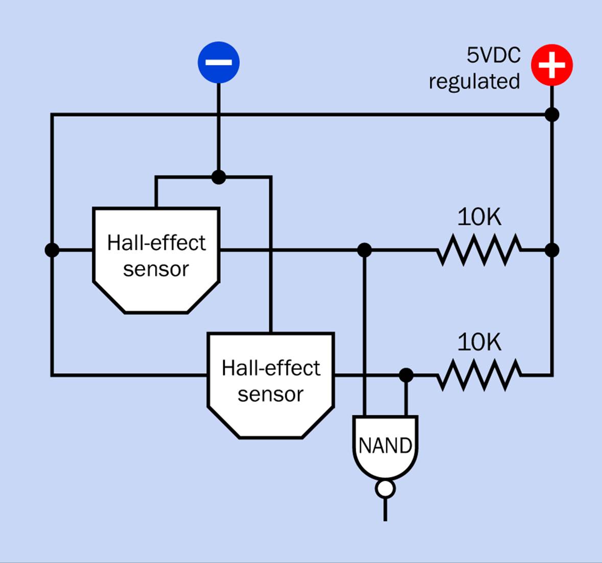
Figure 30-7. The NAND gate in this circuit will have a normally-low output that only goes high when either or both of the Hall sensors are activated.
In this circuit, the NAND gate will deliver a high output when either or both of the sensors are activated. Remember, the voltage provided by a pullup resistor with a Hall sensor is low when the sensor is “on,” while a NAND gate has a low output when both of its inputs are high and a high output when either or both of its inputs are low. Unipolar sensors may be appropriate in this application.
If a Hall sensor is being used to respond to a hand-held magnet whose polarity is unknown, the omnipolar type is appropriate.
A bipolar sensor can behave like a unipolar sensor if a biasing magnet is installed behind the component. In other words, if a sensor is normally activated by a north magnetic pole in front of it and deactivated by a south magnetic pole in front of it, a small magnet can be placed behind it to insure that the sensor returns to its “off” state. When the north pole of a magnet is positioned in front of the sensor, its field can overwhelm the weaker field from the other magnet, causing the sensor to turn “on.”
When magnets are used in this way, they must be of high coercivity, meaning that they resist “coercion” to change their polarity. That is, the first magnet must resist being re-magnetized with opposite polarity by the second magnet. Because neomydium magnets have high coercivity, they are preferred for this kind of application.
Make Even More: Miniature Roll-the-Ball Game
In the midway of a traditional carnival or state fair, you’re likely to have seen some version of the roll-the-ball game. You sit at one end of a ramp that slopes away from you and has several holes in it at the opposite end. Your object is to roll balls down the ramp and sink them into the holes as quickly as possible, bearing in mind that the holes farther from you will give you a higher score.
If you miss all of the holes, the ball disappears down a slot at the end of the ramp and doesn’t score anything at all. The basic layout is shown in Figure 30-8.
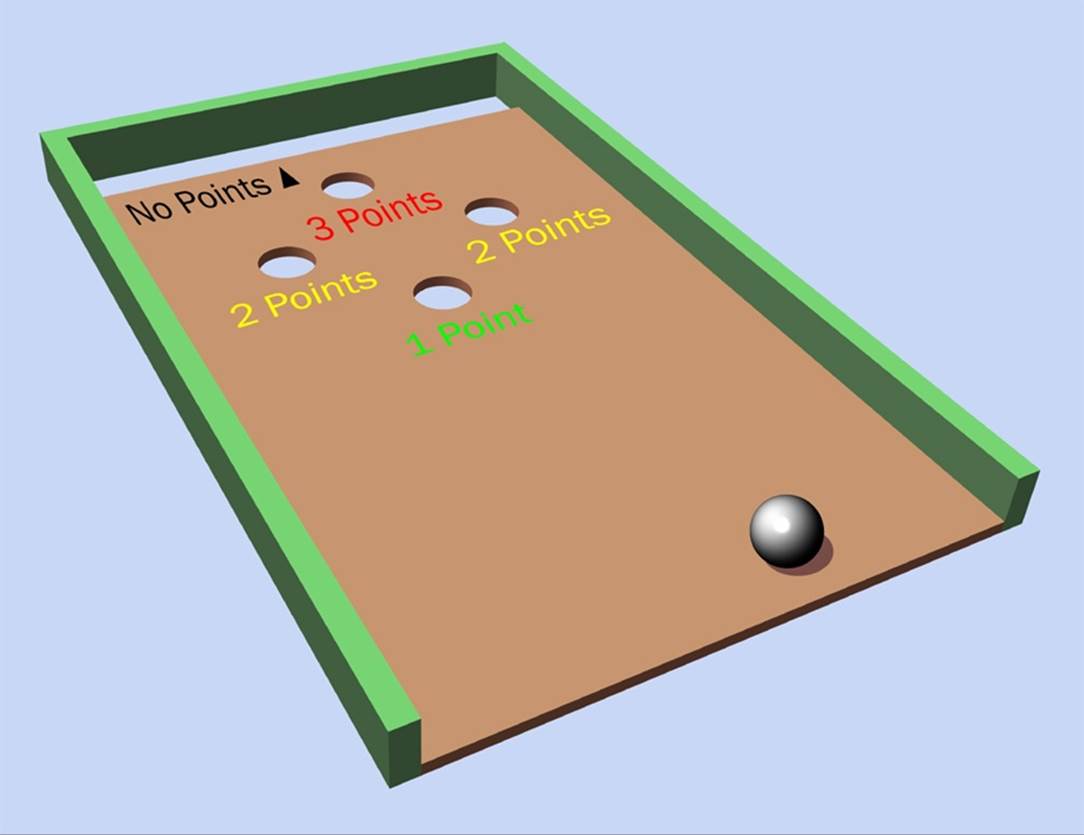
Figure 30-8. The traditional carnival midway ball-rolling game.
Usually a lot of people will be competing at adjacent ramps, and the person who reaches a high score first will receive some kind of prize.
You could make a miniature version of this game using ball magnets and omnipolar Hall effect sensors. Assuming you make it as a single-player game, you’ll need a time limit in addition to a score counter.
Now, how can you control the addition of one, two, or three points to the score? I think the easiest way is to have multiple sensors along the return paths from the higher-scoring holes. The balls will trigger the sensors by rolling past them.
You can do this by making miniature wooden channels, but I think an easier and better way would be to use plastic tubing.
Plastic Bending
Tubing formed from PETG (polyethylene terephthalate) is readily available online and doesn’t cost much. It will keep the returning balls completely under control, even if someone jogs or nudges the game. The only challenge is to bend the tubing smoothly so that it doesn’t get any kinks in it; and the way to do this is by inserting a spring and then using a heat gun.
I’m straying from the business of making electronics, here, but now that I’m dealing with sensors, we have to think about ways in which they can interact with the physical world.
Figure 30-9 shows a piece of PETG tube that has been bent by inserting a spring. The next step will be to pull the spring out, which can be difficult. You may have to rotate the spring, causing its diameter to diminish slightly.
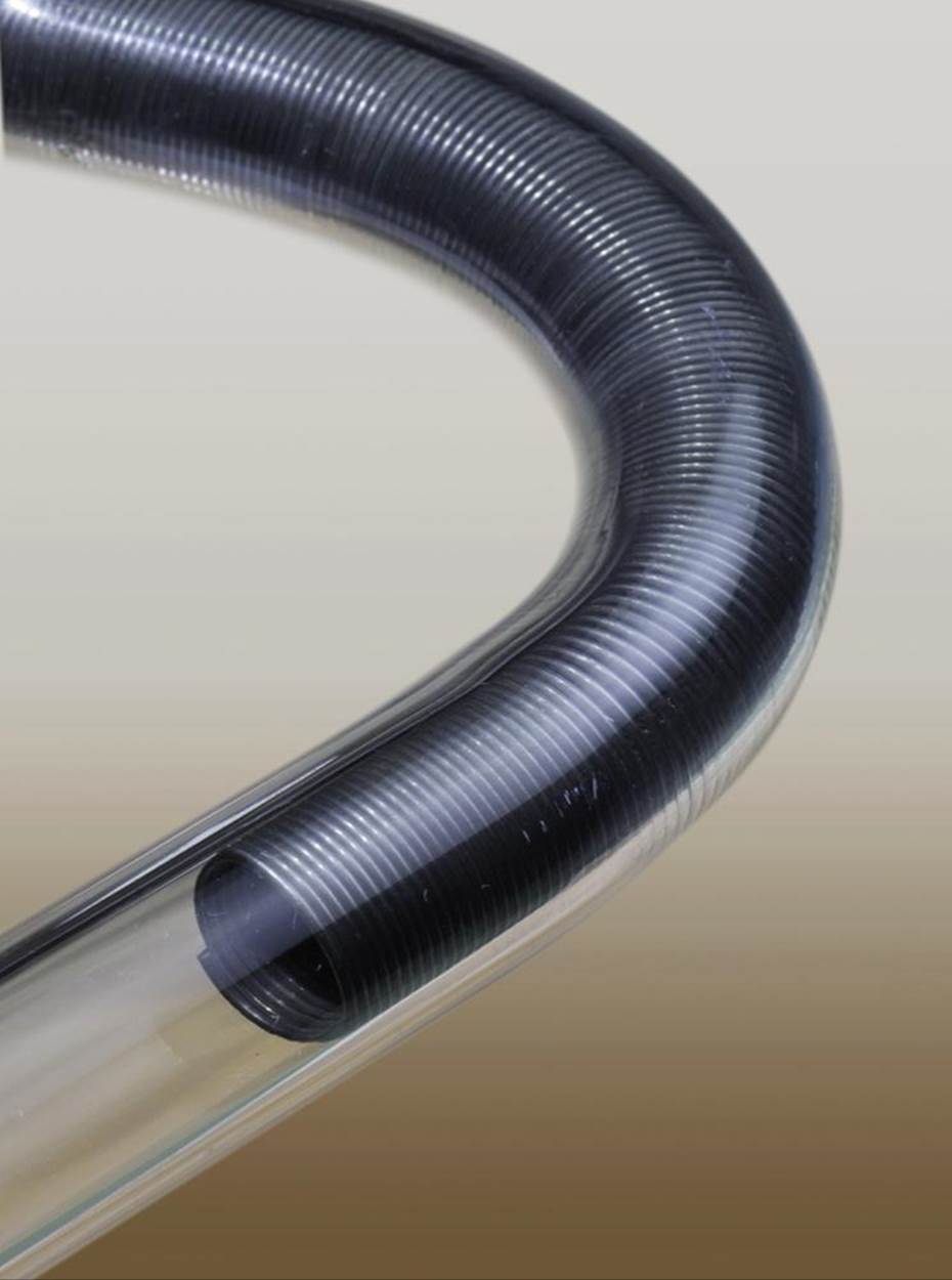
Figure 30-9. A piece of polethylene tube that has been bent into a smooth curve by inserting a spring before applying a heat gun.
Smaller tubing can be formed using this same system. For the ball-rolling game, you might want to use 3/8” magnet balls inside tubing with a 1/2” internal diameter and 1/16” thick walls. But where do you find the tubing and a long spring to push inside it?
I suggest McMaster-Carr, which stocks probably the biggest range of hardware on the planet. Right now they’re selling six feet of PETG tube of the size that I just suggested for about $1.50 a foot. They also sell “cut-to-length” extension springs for around $3.50 apiece. The idea is that you can cut them to whatever length you choose, but for tube-bending purposes, you won’t need to cut them at all.
Of course, you may prefer to work entirely with wood, or you may want to build some other project that requires less shop work than this. I realize that not everyone shares my odd interests, such as bending plastic tubing and rolling balls through it. Still, I’ve come this far, so I’ll finish describing the project.
Rolling-Ball Electronics
If you have one sensor on the return tube from the one-point hole, two sensors for each of the two-point holes, and three sensors on the single three-point hole, that’s eight sensors altogether. You could connect all eight of them through an eight-input NAND chip to a counter, as shown in Figure 30-10, which shows ball-return tubes as they could be laid out under the ramp.
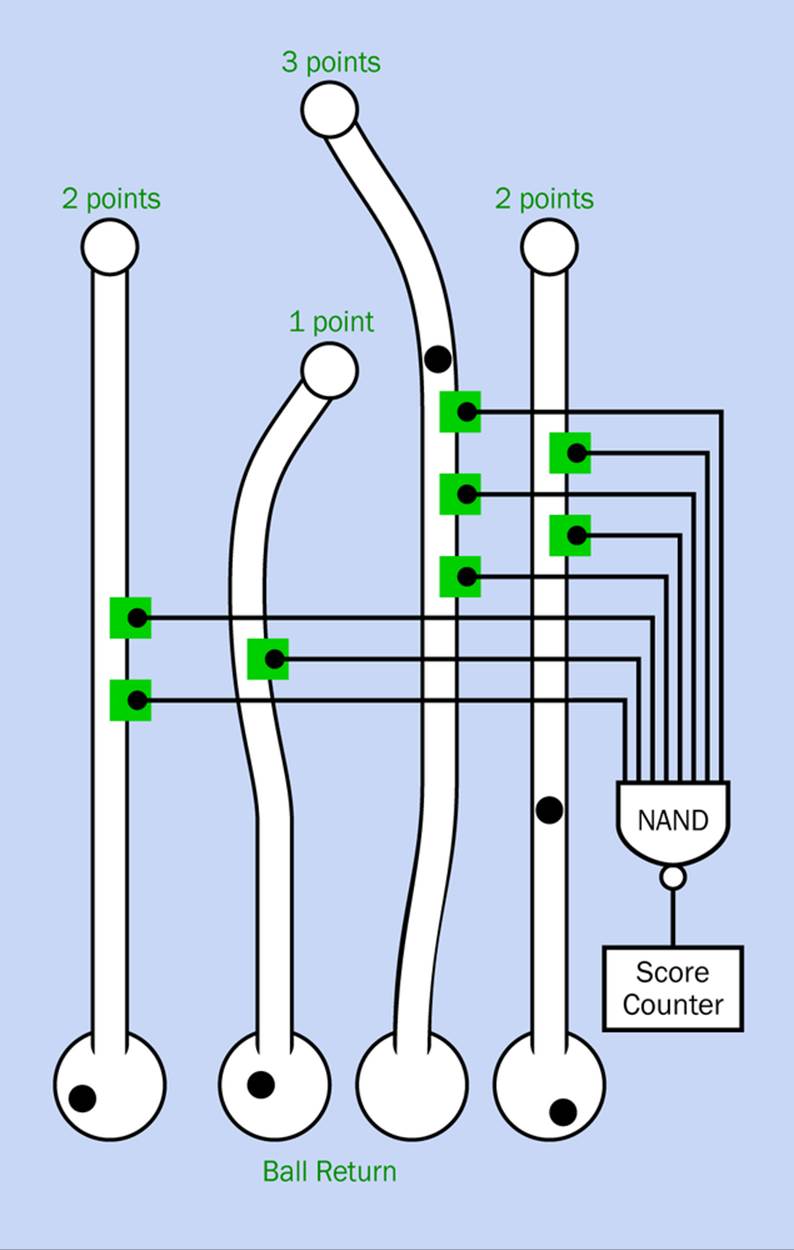
Figure 30-10. Hall-effect sensors (shown here as green squares) to count points in the rolling-ball game.
You’ll remember from Figure 30-7 that a NAND is appropriate for use with Hall-effect sensors, as its output goes high each time a sensor pulls one of its inputs low.
Omnipolar sensors would be appropriate for this application, as they should respond to the magnetic field created by a rolling ball regardless of its changing polarity. I’m hoping that the sensors will give noise-free signals, which is a primary reason for using them instead of reed switches. There’s no reason to debounce a reed switch (using the debouncing techniques that I mentioned in Make: Electroncs) when you can use sensors that should be bounce free.
The output from the NAND chip can connect with a 4026B decade counter. This chip is specifically designed to power a seven-segment LED numeral. The carry from this chip can go to a second 4026B and a second numeral, so you can count up to 99 points. The 4026B is another item that I described in Make: Electronics (for use with a reaction-timer game).
Add a reset button that will zero the counters and begin a single 30-second pulse from a 555 timer, which will stop the counters at the end of its cycle. And that’s it! Your very own arcade game with rolling magnetic balls—like an early, primitive pinball machine.
Wait—could you build an entire pinball machine with neodymium ball magnets?
Maybe so, but quite apart from the complexity, you’d have to make sure that the balls never come into contact with each other. In the ball-rolling game, pulling magnets apart that have accidentally come into contact will just add to the tension as you try to beat a high score.
All materials on the site are licensed Creative Commons Attribution-Sharealike 3.0 Unported CC BY-SA 3.0 & GNU Free Documentation License (GFDL)
If you are the copyright holder of any material contained on our site and intend to remove it, please contact our site administrator for approval.
© 2016-2026 All site design rights belong to S.Y.A.