Make: More Electronics (2014)
Chapter 34. Experiment 34: Ambient Sensing
In this section, I’m returning to the basic concept that I have used before, of choosing a random number by stopping a fast timer at an arbitrary moment.
This was the technique in the Ching Thing in Experiment 28, and also in the Hot Slot game in Experiment 21. However, both of those games required the player to do something that would stop the timer. What I’m going to describe here is a way for a sensor to inject a random factor without any user input.
First I’ll recap the basic setup of a slow monostable timer, which starts and stops a fast asynchronous timer, which drives a counter. I’ll be using this in all the sensor-based randomizing applications below.
Then I’ll pause for a moment to show you how a timer can be wired to restrict the random number sequence. Instead of counting from 0 through 15 or 0 through 9, it can count to any lower number. You can even make it count from 0 through 1.
Finally, I’ll throw in the sensors.
One Timer Controlling Another
In the circuit in Figure 34-1, the timer at the top is wired in the same way as the timer in Figure 27-1, to produce a single clean pulse when the DPDT pushbutton is pressed.
The output from the first timer lights an LED (the little yellow circle) just to confirm that it’s working. It also connects with pin 4, the reset pin, of the second timer. When the reset pin is high, the timer is allowed to run. So, the high output from the first timer unlocks the second timer (for a limited time only).
The second timer sends a stream of pulses to the ring counter, and you’ll see the LEDs labelled 0 through 9 counting in sequence.
When the first timer reaches the end of its cycle, it pulls down the reset pin of the second timer, stopping it and leaving one LED illuminated.
Press the Counter Reset button, and then press the Rerun button—which is not debounced, because for testing purposes, I’m expecting you to let go of it before the pulse from the slow counter is over.
You should find that at the end of each cycle, the same LED is left glowing every time. No randomness, here—the components are doing what we expect them to do. They are behaving consistently.
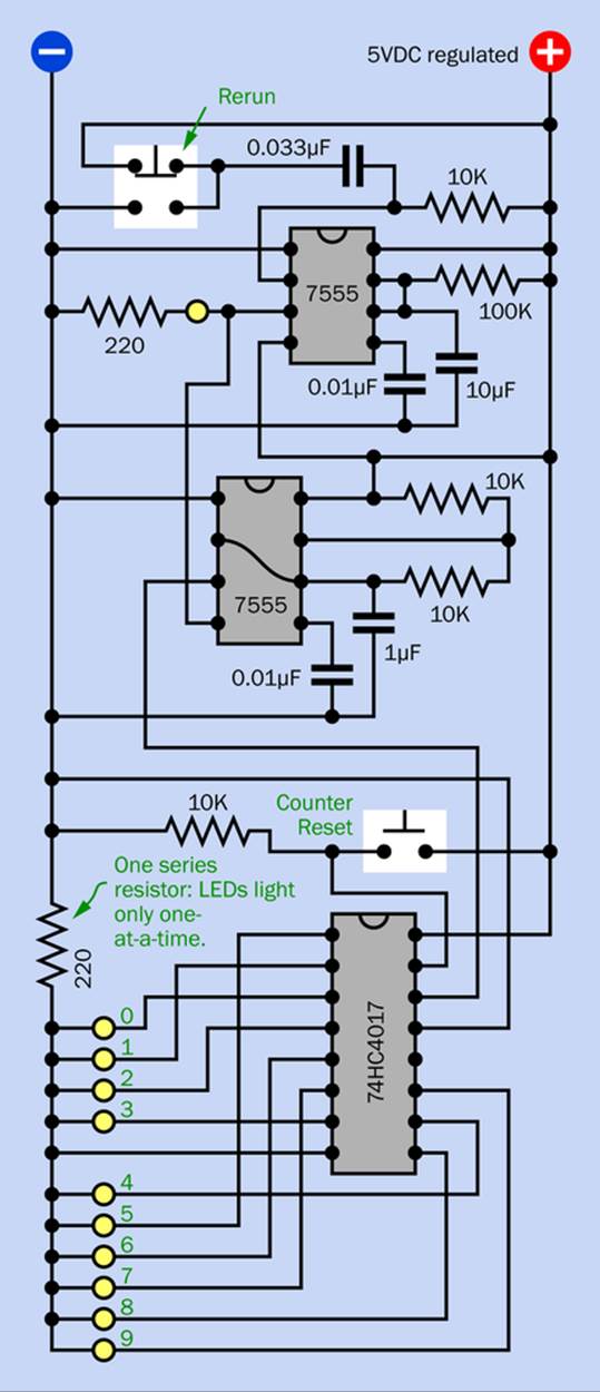
Figure 34-1. This basic circuit illustrates the concept of a slow timer enabling a fast timer for a limited period. The ring counter controlled by the fast timer should stop in the same state every time, so long as you press the Counter Reset button before each run.
Temperature Control
Now we’re going to make things a little more interesting by using a thermistor, which is like a resistor, except that it changes its resistance with temperature. A photograph of a thermistor is shown in Figure 34-2. It’s very tiny because the smaller it is, the more rapidly it will respond to changes in temperature. It has long leads because the longer they are, the less heat they will transport to or from the thermistor itself. For the same reason, the leads are very thin.

Figure 34-2. A high-quality thermistor. Its small size allows it to respond rapidly to changes in temperature.
The thermistor that I’d like you to use is rated at 100K, which is the baseline resistance it should have at 25 degrees Celsius. A thermistor has no polarity, so you don’t have to worry about which way around you connect it.
To insert it in the circuit, simply remove the 100K resistor from the first timer and substitute the thermistor.
Repeat the cycle. So long as the temperature of the thermistor remains constant, you should end up with the same LED illuminated every time, because the first timer will give the second timer the same window of opportunity in which to do its counting operation.
Run the test a few times. Don’t forget to press the Counter Reset between each test and the next. Now grip the thermistor between your finger and thumb to increase its temperature. Run the test again. Does the result vary?
Random Factors
In addition to the changing resistance of the thermistor, various factors may have an effect:
§ The timers themselves change their performance slightly as they warm up with use.
§ The Rerun pushbutton may not perform exactly the same way every time.
§ You may have variations in your power supply.
§ Connections on your breadboard have some resistance, which may vary if you touch any of the wires or components.
§ There could be some other ambient factor that I haven’t thought of.
Automating the Randomizing Circuit
We can speed up the testing process by getting rid of the user input.
The first step is to change the first timer from one-shot to astable mode. It can run for one second, then pause for one second, then run for another second, and so on. This way you can just sit back and watch the results instead of constantly having to press the Rerun button. Figure 34-3 shows the rewired circuit.
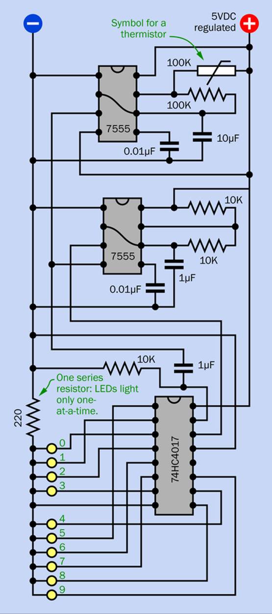
Figure 34-3. The previous version of the randomicity test circuit, rewired so that it runs automatically, without user input.
The second step is to eliminate the Counter Reset button and fix the counter so that it resets itself. The 74HC4017 counter’s reset pin responds to the rising edge of a transition from low to high. Well, the output from the first timer rises from low to high at the beginning of each cycle, so let’s connect it to the counter reset pin—through a capacitor, so that the reset pin only goes high momentarily.
I have incorporated this modification in Figure 34-3. You can also see a breadboarded version of the circuit in Figure 34-4.
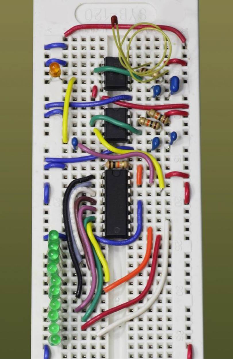
Figure 34-4. The original thermistor testing circuit described in the text has been modified to run itself without user input.
Now the system should run itself.
Background: Lower Counting
I’m going to mention this important detail before I leave the subject of the ring counter.
§ You can easily modify most counters so that they count to a lower number. The ring counter is no exception.
Pin 1 of the 74HC4017 timer normally goes high to light LED number 5. What do you think will happen if you put a jumper between Pin 1 and Pin 15, the reset pin?
The counter will illuminate LEDs 0, 1, 2, 3, and 4 as usual. Then it gets to Pin 1, which normally lights LED 5, and the high output feeds back to the reset pin. Within a fraction of a second, the counter resets itself to 0 and stops its output to pin 1. Consequently, LED 5 never has a chance to emit any visible light.
The counter then resumes counting from 0 upward, so long as clock pulses are still arriving. It will repeat the 0 through 4 sequence indefinitely and has been transformed from a decade counter into a half-decade counter.
§ Connecting an output pin back to the reset pin is standard procedure to change the cycle length of a counter.
This is particularly easy in the case of a counter with decoded outputs, as you can choose any number as your cutoff in the count cycle. When using a counter with binary weighted outputs, you have fewer options. For example, suppose you connect the third binary output pin back to the reset pin. The third pin has a value of 4, so the counter will restart itself after counting from 0 through 3. What if you want the counter to restart at, say, a value of 6? That will be a little more difficult.
You can address the problem by using logic gate(s) to select a combination of pins corresponding with the cycle length that you want. An AND gate between the second and third pins will generate a positive output when the counter reaches binary number 110, which is 6 decimal. Connect the AND output to the reset pin, and your binary counter now runs from 000 to 101 (0 through 5 decimal) before repeating:
§ Limiting a counter is a valuable technique when you want a counter to choose a random number outside of the usual range, for a game.
§ To convert a 74HC4017 counter so that it only counts from 0 to 1 before repeating, just run a jumper from pin 4 (the pin that has value 2) back to the reset pin.
Now, I’ll get back to sensors and randomicity.
Speed Adjustment
If you’re not achieving much variation from your automated randomizing counter output, you should increase the running speed of the second timer. 50Hz is very slow, and I chose it only so that you could see the LEDs flashing in sequence. Remove the 1µF timing capacitor from the second timer and substitute a 0.1µF capacitor, to get 500Hz. Or use a 0.01µF capacitor to get 5,000Hz.
The faster the second timer is running, the more its interrupted state is likely to vary because of small changes in the run time. This is explained in Figure 34-5.
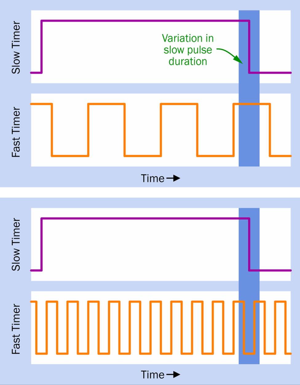
Figure 34-5. When a slow timer controls a second timer, variations in the slow timer speed (shown by the darker blue rectangle) will stop the second timer at a wider range of pulses when the second timer is running faster.
In the upper half of the figure, the slow timer pulse length (purple) can vary between the limits shown by the darker blue rectangle, as a result of sensor variations in its timing circuit. Because the second timer (orange) is not running very fast, it will be stopped at the same number of pulses, both at the low end and the high end of the slow timer’s range.
In the lower half of the figure, the second timer is running faster. Consequently, it will stop at two different possible pulses at the low end and the high end of the slow timer’s range.
If you use a 1nF capacitor to create 50,000Hz, I’m willing to bet that the second counter will stop in a different place almost every time—at least, so far as you can tell.
So, have we solved the whole problem of automatically randomizing the behavior of games to make them seem unpredictable?
Well, maybe.
First I want to go a bit farther into the topic of thermistors.
Quick Facts About Thermistors
Thermistors change their resistance in response to temperature. The NTC type decreases its resistance as the temperature rises and has a linear response over a reasonably wide range (usually from around -40 to +125 degrees Celsius). The PTC type increases its resistance quite suddenly when its temperature goes up.
NTC stands for Negative Temperature Coefficient, while PTC stands for Positive Temperature Coefficient. The PTC type is often used as a substitute for a fuse, to block current from a power supply when it exceeds a maximum value.
The NTC type is the one we’re using here.
Thermistors are cheap. Many of them cost less than 50 cents, and they are available in a wide variety of basic resistance, which is usually measured at 25 degrees Celsius,
To test a thermistor, set your meter to measure kilohms and touch the probes firmly against the leads of the component. Don’t let it touch your hand, as the contact will affect not only the temperature of the thermistor but also the resistance that you measure. Press the probes against the thermistor leads on a firm, insulating surface, and wait for the meter reading to stabilize.
Now move your other hand close to the thermistor, without actually touching it, as that could affect the contact being made with the meter probes. You should see the thermistor resistance gradually changing as it feels heat radiating from your skin. Physically small thermistors will respond more rapidly than larger thermistors, as they have less mass to be heated or cooled.
Making a Thermistor More Random
Many factors can affect the temperature around a circuit, but heat is also generated by the circuit itself. You could put a thermistor inside a box with your circuit. To make the thermistor more responsive, you could tape it to a 220-ohm resistor, wired straight across your power supply. The resistor would consume about 100mW at 5VDC, well within the usual quarter-watt operating range, but sufficient to generate a little heat. Naturally, this wouldn’t be a very smart idea for battery-powered devices. You should also be careful not to push the thermistor to one extreme end of its range, where it will no longer respond to changes in temperature—although this is unlikely.
Alternatively, you can mount a thermistor so that it is exposed to ambient air at the back of the box, where it will respond to local temperature fluctuations. Better still, use two thermistors, in series or in parallel, with one inside the box and one outside the box.
If this isn’t random enough for you, maybe you’d like something a little more exotic.
Humidity Sensor
Humidity in a room usually changes very slowly, unless you have a bathroom or a kitchen in the immediate vicinity. But you could factor those slow changes into your timer control circuit.
The Humirel HS1011 humidity sensor is available from Parallax (and other suppliers) for less than $10. It only has two leads, and the capacitance between them will change as the humidity changes.
Yes—the capacitance. That’s a novel concept. How can we use it in the timer control circuit?
Easily! Just substitute the humidity sensor for the timing capacitor with the first timer in Figure 34-4. The Humirel datasheet tells me that the capacitance of the sensor varies from 177pF to 183pF. Those are small numbers, so you’ll have to use a lower-value timing resistor.
Humidity Control
The humidity sensor could potentially be used to switch a humidifier on or off, if you like the idea of a humidity-controlled environment. Books, papers, old audio tapes, and human sinuses tend to do better when the amount of moisture in the air is controlled.
One way to achieve this would be by using the variable capacitance to adjust the running speed of a fast astable timer, while a second timer activates it for a brief period. The astable output is connected with a four-bit binary counter. The counter is connected with a four-bit multiplexer, with its sixteen input/output pins wired in series as a long voltage divider. The voltage selected by the multiplexer becomes the variable voltage input for a comparator. The reference input to the comparator is set by a potentiometer, which is your humidity control. The output from the comparator goes to a solid-state relay that turns the humidifier on and off.
Is that complicated enough for you? It sounds like at least an all-day project, to get everything working right. Maybe you would do better to buy an off-the-shelf humidistat, which works just like a thermostat. But that would be so boring! Wouldn’t you rather have the aggravation of building your own version, followed by the elation when it finally works, and the mystified looks that you will get from your friends, who may not understand that it’s a whole lot of fun to build gadgets that are unnecessary?
I would definitely prefer the aggravation-elation-mystification cycle myself, if only I had time for it. Right now, I have to move along to another sensor option.
Accelerometer
I wrote about accelerometers for a column in Make magazine. They’re getting quite cheap these days. Because they respond to a force in any direction, they can sense which way up they are by measuring the force of gravity. If you have a handheld device, an accelerometer will vary its output resistance as the person shifts his grip on the device slightly. So, here’s another possible source of random resistance values.
The actual accelerometer is likely to be a tiny surface-mount device, but it’s also likely to be available mounted on a breakout board, like the one in Figure 34-6. This makes it really easy to use.
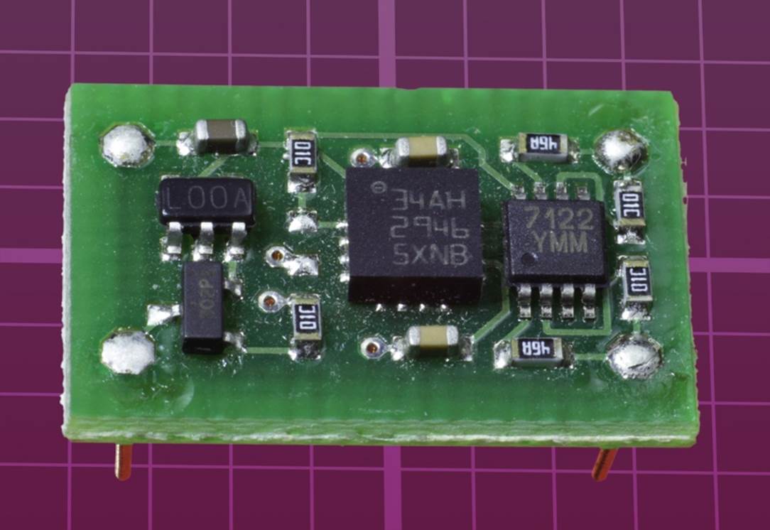
Figure 34-6. A surface-mount accelerometer mounted on a breakout board. The accelerometer measures any force, including the force of gravity. Consequently, its output changes depending which way up you hold it. The output is converted to a simple change of resistance between pins on the board. Graph squares are 0.1” x 0.1”.
Touch Sensor
This, I think, is the most promising device of all. It’s a thin sandwich of flexible plastic layers, with a pressure-sensitive resistor between them. You’ll find a picture of it in Figure 34-7. I’m not sure exactly how it works, but it seems to be reliable, and it has a very wide range of resistance values. When you don’t touch it at all, the resistance is almost infinite. When you push hard, its resistance drops to around 1K.

Figure 34-7. A touch-sensitive pad that changes its resistance when you press it with your finger tip.
You could use it as a substitute for a Start button that will also run a timer. In other words, the touch sensor can do dual duty as a high-tech on-off switch and a randomicity generator. Its very wide range of resistance values should provide you with an equally wide range of randomicity values.
But, I have to admit, I’m speculating about this. I don’t have time to put the sensor through, say, a thousand cycles, to check if it gives a good variety of values. Even if I did have time, there might be something about the way I touch it which tends to create some resistances more than others. Even if the sensor worked well for me, there might be someone else who could touch it in such a consistent way, it wouldn’t be so random.
It seems I’m forever doubting the performance of these components and saying “What if” this, and “What if” that.
I admit that I tend to be a skeptical kind of person, but the real problem is that I have been running these experiments on an empirical basis.
Empirical Issues
An “empirical” study means that the results are based on observation or experience.
Well—what’s wrong with that? It’s certainly better than just sitting around and wondering what might happen.
That’s true. Hands-on work is more valuable than a vague prediction of what may happen (indeed, that’s what this book is all about). Most research uses observations to confirm the conclusions. But there is an additional aspect of research: it often has a theoretical basis.
For instance, when astronomers very carefully measured the apparent position of the planet Mercury as it disappeared behind one side of the sun and reappeared from the other side, they weren’t just doing it because they had some spare time and wanted to test their equipment. Einstein’s theory of relativity predicted that the sun’s gravity would bend the light reflecting off Mercury. Scientists made their observations because they wanted to find out if he was right. (Indeed, he was.)
But if you don’t have a theoretical basis, and you’re hoping that your observations today will still give you the same results tomorrow, there are no guarantees—especially if you have a lot of uncontrolled factors, such as different people pressing a sensor in different ways.
You may feel that a thermistor, or a humidity sensor, or an accelerometer, or a pressure sensor should behave similarly with different users, and they should create a good spread of random values, but you cannot be certain of that. If someone asked you, your correct response would be:
§ The output seems to be random today, and I don’t see why it shouldn’t be random tomorrow. But I can’t prove it.
Well, what if I told you that you can actually connect some components together that will generate an unpredictable stream of numbers, all on their own, without any external factors interfering? And what if you could guarantee mathematically that the sequence of numbers will be the same every time? And what if the sequence could continue for so long before it repeats, no human brain would ever be able to predict which number comes next?
That sounds like the perfect pseudorandom number generator, so long as you don’t always begin the sequence in the same place. But it also sounds complicated, and you may be wondering if it’s necessary.
It’s not very complicated. Whether it’s necessary depends on what you want to use it for.
How Random Is Random?
In a typical electronic game, we just need an input that seems pretty much random. If we are generating arbitrary numbers from 0 through 15, and number 13 comes up just a bit more often than the others during a series of hundreds of games—probably it doesn’t matter.
In the Hot Slot game, the player who goes second is hoping to make a 12.5% profit. Suppose the random number generator in the game chooses one slot maybe 0.5% more than another—probably it doesn’t matter.
But in some experiments, we require numbers to be precisely evenly weighted. If we are generating a random sequence of ones and zeroes over a long period of time, we may need to be absolutely positive that the series will contain 50% ones and 50% zeroes, not a ratio of 50.1% to 49.9%.
Maybe you feel you’re unlikely to need such accuracy. But think back to the Telepathy Test in Experiment 15. Suppose we change it from a two-person experiment to a single-person experiment.
The challenge will be for someone to use psychic powers (if such things exist) to guess whether an LED is on or off. A circuit will turn the LED on and off in a seemingly random sequence, but during, say, 254 tests, we must be absolutely sure that the LED will be on 127 times and off 127 times. Otherwise, if the person makes correct guesses slightly more than half the time, we won’t know how to evaluate his performance.
In any paranormal research, even a small variation from a median value can be significant, and therefore it really matters if one number is generated more often than another.
Could we rebuild the Telepathy Test in a single-player version that could produce really solid results? Actually, I don’t think it’s too difficult, and I want to give it a try.
I’m going to approach the challenge in two stages. First, I’ll show you how to create a perfectly pseudorandom number generator. Then I’ll incorporate it into the test.
All materials on the site are licensed Creative Commons Attribution-Sharealike 3.0 Unported CC BY-SA 3.0 & GNU Free Documentation License (GFDL)
If you are the copyright holder of any material contained on our site and intend to remove it, please contact our site administrator for approval.
© 2016-2026 All site design rights belong to S.Y.A.