Make: More Electronics (2014)
Chapter 2. Experiment 2: Getting Some Numbers
Here’s my plan. Looking ahead to the next experiments, I’m going to be showing you some components that were not included in Make: Electronics. The first three will be:
§ Phototransistor
§ Comparator
§ Op-amp
These devices will be doing some things to interest and entertain you in Experiments 3 through 14. You’ll also be dealing with topics such as circuit design, especially using analog components.
After that, we’ll be using digital chips such as:
§ Logic gates
§ Decoders, encoders, and multiplexers
§ Counters and shift registers
Then I’ll be discussing randomicity, and sensors—
But first, here and now, I have to make sure that we’re all on the same page regarding a few basic concepts. Even if you feel that you are thoroughly familiar with these concepts, well-informed people can still have a few gaps in their knowledge, so please take a few moments to go through this section of the book. You’ll need this information to make sense of the sections that come later.
Requirements
§ Remember that you will find components for each experiment listed at the back of the book. See Appendix B.
I’m assuming that you already have the 5VDC regulated power supply shown previously in Figure 4. Any time you see the word “regulated” in a schematic, the basic regulated power supply consisting of an LM7805 and two capacitors will be necessary. In this experiment, because you are going to be making accurate measurements, you need an accurately controlled voltage.
Transistor Behavior
Numbers are unavoidable in electronics. In fact, you can see them as your friends, because they tell you what’s going on. Making accurate measurements is also very necessary, because if your measurements aren’t accurate, your numbers will mislead you and will be worthless.
Therefore I want to run a version of Experiment 1 with a trimmer potentiometer instead of a trail of Elmer’s glue, and a meter instead of an LED, so that you can measure the performance of the circuit. (This will be similar to Experiment 10 in Make: Electronics, but I’m going to go further into the topic of amplification.)
Are you good at making accurate measurements? Now’s the time to find out.
Step 1
Begin by setting your meter to measure microamps DC. Depending on the type of meter you’re using, you may simply need to insert the red lead in the socket reserved for measuring current, and turn the selector knob to amperes. If your meter doesn’t do autoranging, you’ll have to choose microamps with the selector. Either way, make sure you are measuring DC, not AC, and make sure the red lead of your meter is in its “amperes” socket.
You’ll be using your meter in the circuit as shown in Figure 2-1.
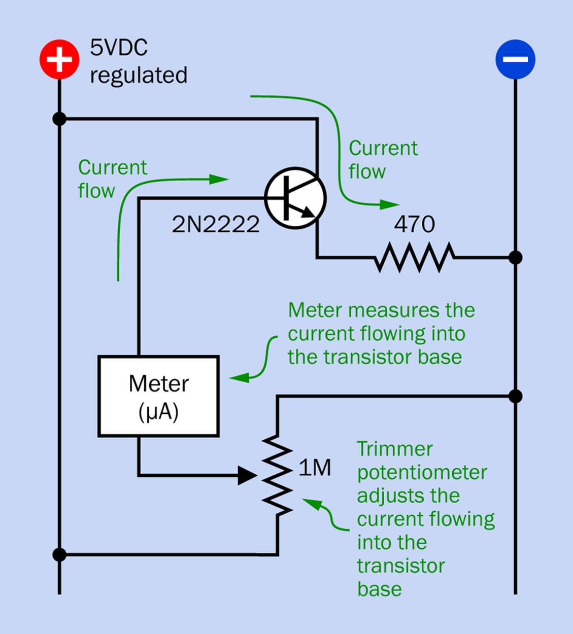
Figure 2-1. The meter measures current flowing into the base of the transistor.
If you have any trouble interpreting this schematic, take a look at Figure 2-2. This shows a manual-ranging meter measuring microamps between the wiper of the trimmer potentiometer and the base of the 2N2222 transistor, using flexible jumpers gripped by minigrabbers. The twisted black and red wires entering the picture from the right are supplying 5VDC regulated power to the breadboard. The reading on the meter is arbitrary.
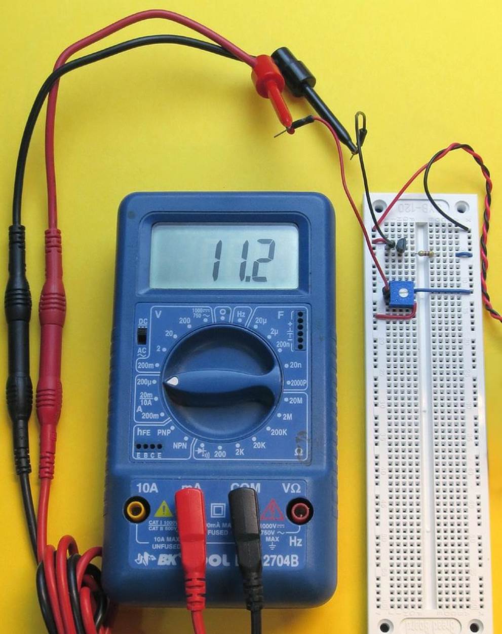
Figure 2-2. Setting up a meter to measure microamps flowing from the wiper of the trimmer potentiometer to the base of the 2N2222 transistor. See text for more details.
A closeup of this same breadboard is shown in Figure 2-3. The black and red wires coming in from the left, terminating in round plugs inserted into the breadboard, are from the meter. The trimmer potentiometer is oriented in the same way as in the schematic so that each of its leads is inserted in a separate row of holes in the breadboard. If you turned the trimmer 90 degrees, two of its leads would be in the same row of holes, and it wouldn’t work.

Figure 2-3. A closeup of the breadboard from the previous photograph.
Adjust the trimmer until your meter shows 5µA. This is the base current—the current flowing through the lefthand side of the trimmer and into the base of the transistor.
Step 2
Make a note of the base current. Maintaining a lab notebook is a really good idea, and you might as well start one now. If you record each experiment on a step-by-step basis, it can be useful to refresh your memory later. The Maker’s Notebook is a product that makes this convenient.
Step 3
Remove the meter probes from the breadboard and substitute a piece of hookup wire. Change the meter to measure milliamps, if it does not do autoranging, and move it to the position shown in Figure 2-4.
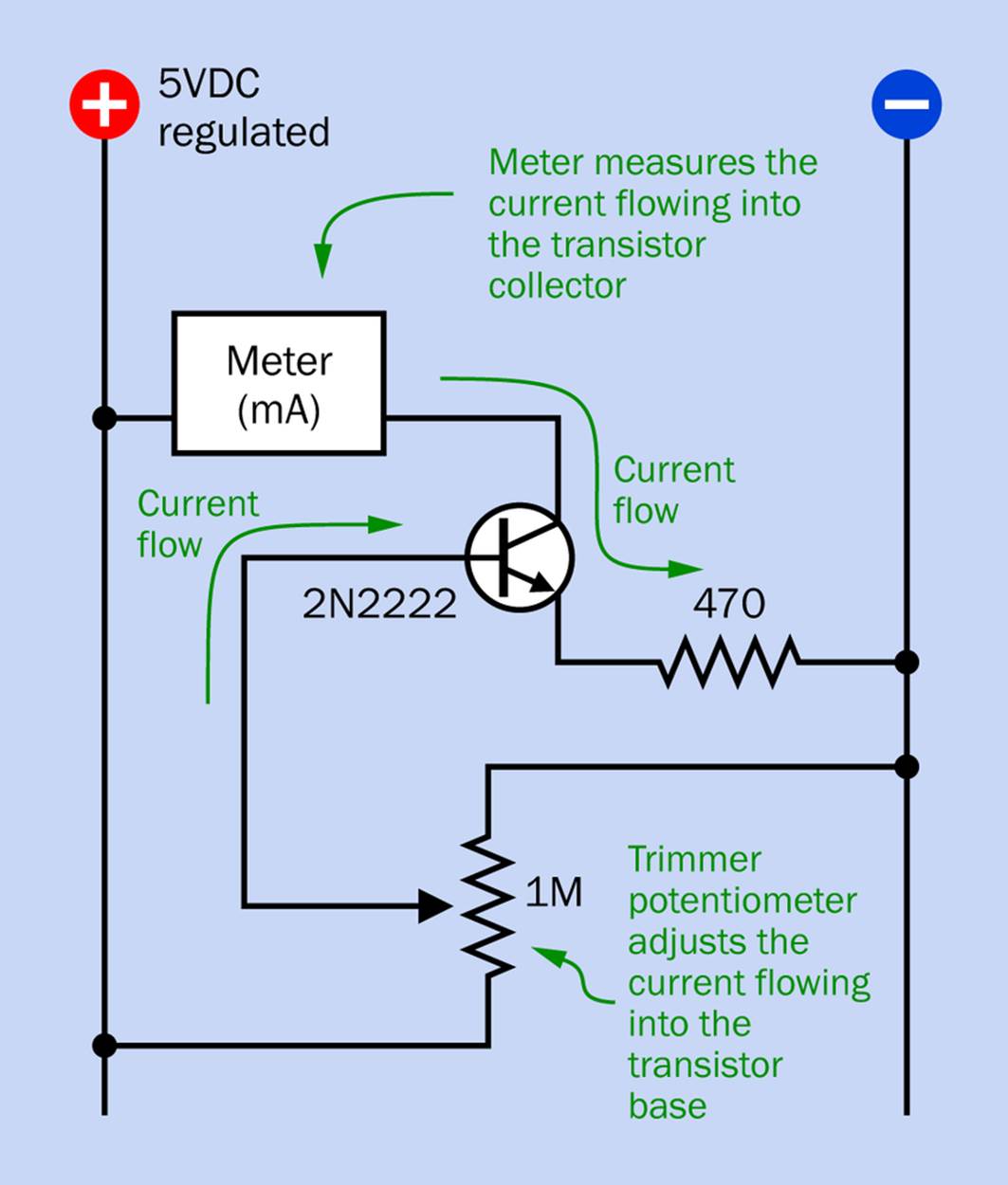
Figure 2-4. The meter now measures current flowing into the collector of the transistor.
Figure 2-5 shows a photograph of this configuration. The yellow piece of hookup wire has been inserted where the meter wires were before, and the meter now connects the positive bus on the breadboard with the collector of the transistor.
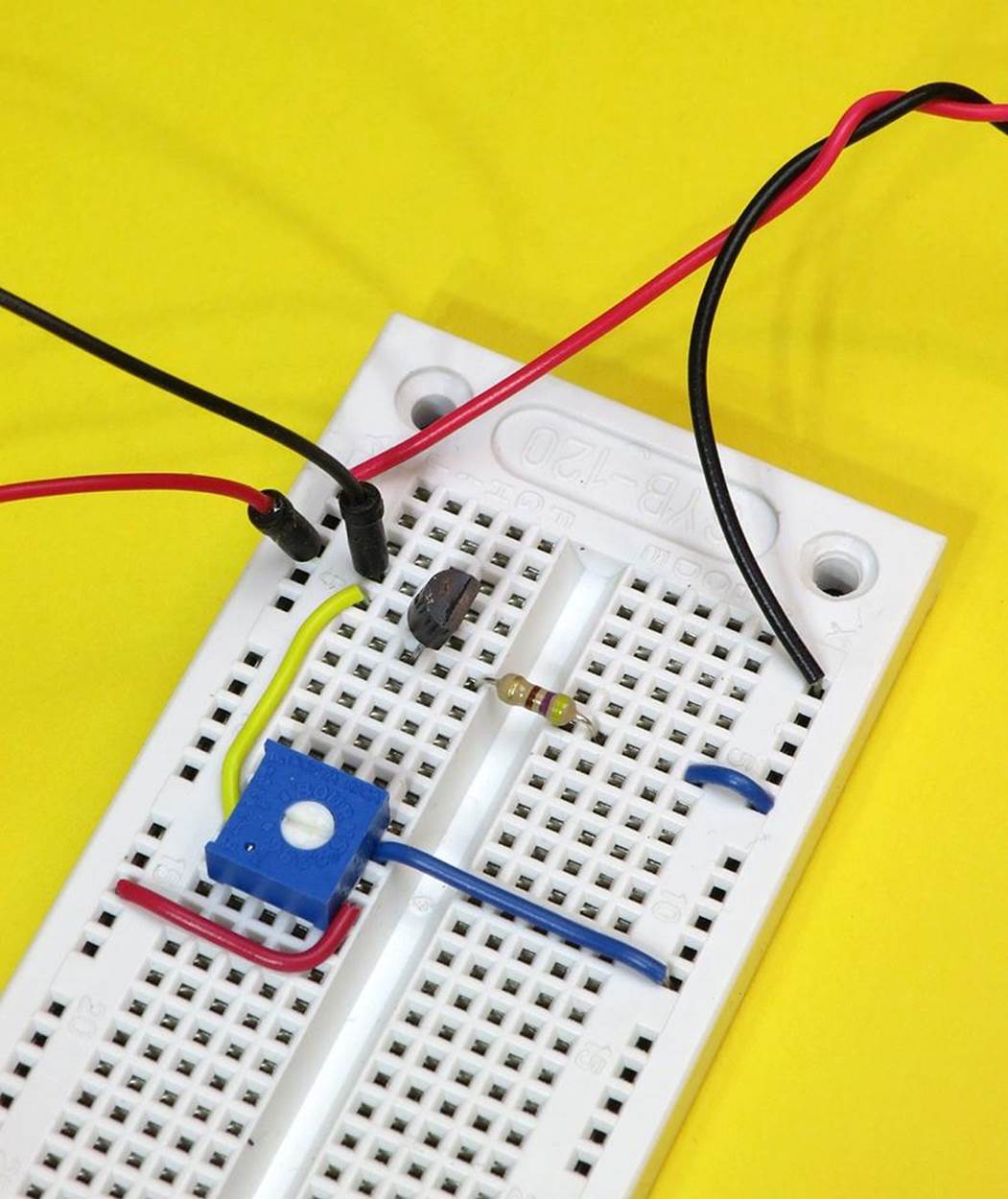
Figure 2-5. The red and black wires on the left run to the meter, which now measures current flowing into the collector of the transistor.
Step 4
Alongside the base current that you just wrote down, write the reading that you now see on the meter. This is the collector current.
Step 5
Go back to Step 1, but adjust the trimmer to increase the base current by an additional 5µA. (Don’t forget to reset your meter to microamps, if necessary.)
Repeat steps 1 through 5 to make a table in which the left column shows the base current from 5µA to 40µA in steps of 5µA, while the next column shows the collector current at each step. That’s eight values altogether—not too much work, even though swapping the meter to and fro is repetitive. The result should look something like the first two columns in Figure 2-6. I measured those numbers myself; are they similar to yours?
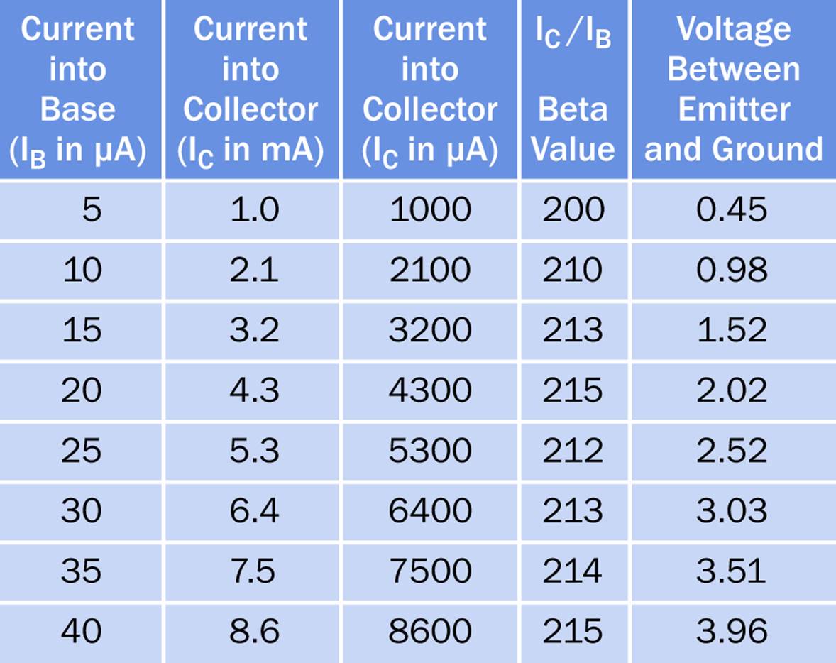
Figure 2-6. Comparing base current with collector current in an NPN transistor.
Now you need to convert each value for collector current from milliamps to microamps, because there’s going to be a division that only makes sense if all the units are the same. There are 1,000 microamps in a milliamp, so you just have to multiply the collector current that you measured in milliamps by 1,000 to get the equivalent in microamps. You can see this in the third column in the table of values that I measured, in Figure 2-6.
Finally, get out a pocket calculator and divide the collector current (in microamps) by the base current (in microamps) for each of your eight pairs of readings. After the first one or two, you should find that the ratio is almost precisely constant. This is shown in the fourth column of my table.
§ The current into the collector, divided by the cutting into the base, tells you the amplifying power of the transistor.
Warning: Meter at Risk!
Be careful when measuring current. Excess current can blow the fuse in your meter. It’s a good idea to keep spare fuses available. Also, when you stop measuring current and set the meter aside, you may forget to swap the red lead back into the correct socket for measuring voltage. It’s a good idea to do this as a matter of habit, because the meter is much less vulnerable in this mode.
Abbreviations and Datasheets
In Figure 2-6, notice the abbreviations IB and IC. Remember that letter I is generally used to mean “current.” So, if you’re thinking that IB is the current into the base, and IC is the current into the collector, you’re right.
You’ll find these abbreviations in almost any transistor datasheet, and they are usually telling you the maximum values that you’re allowed to use. This is very helpful information. If you start thinking about building a project of your own, the maximum values for base and collector current will enable you to choose a transistor that won’t be overloaded.
Now, what do you think IE might mean? If you guess that it represents the current flowing out of the emitter, once again, you’re right, although this abbreviation is less often used. The reason is that IE is actually a combination of IB and IC. The current that flows in through the base and the collector can only get out of the transistor through its emitter, and therefore:
IE = IB + IC
Here are some other common abbreviations used with NPN transistors:
§ VCC is the power supply voltage. It stands for Voltage at Common Collector, but is used to identify the supply voltage even if there are no bipolar transistors in a circuit.
§ VCE is the voltage difference between collector and emitter.
§ VCB is the voltage difference between collector and base.
§ VBE is the voltage difference between base and emitter.
A datasheet will also usually refer to the “beta value” of a transistor, often using the Greek letter β. This expresses how much a transistor will amplify its base current, and is calculated simply by taking IC and dividing it by IB, which is what you did after Step 5. Notice that the fourth column in the table is headed “Beta Value.”
The consistency of the beta value in the fourth column of the table in Figure 2-6 tells you that the transistor is a linear device. In other words, if you plot a graph of the values, you get a straight line—as shown in Figure 2-7.
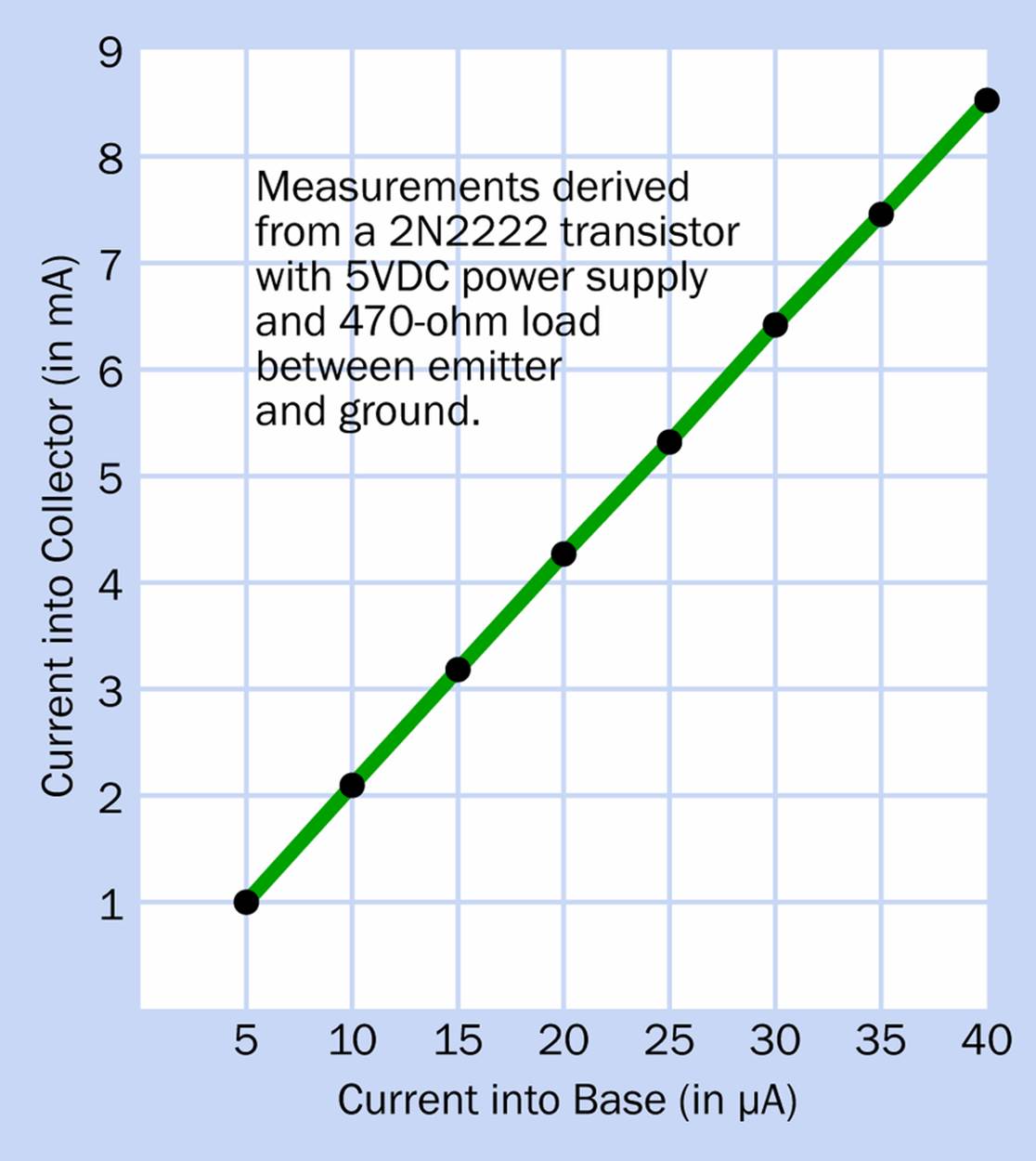
Figure 2-7. A graph drawn from data in the first two columns in the preceding table.
You can create a graph from your own numbers, using graphing software (Excel will do the job) or old-style graph paper. The Maker’s Notebook is full of graph paper, or many sources online will allow you to download PDF files that will generate graph paper on your computer printer. Just search online for “print graph paper.”
Why doesn’t the beta value that you measure stay absolutely, exactly the same for each pair of values? Because your meter isn’t absolutely accurate (especially when measuring very small currents in microamps), and your transistor may have tiny manufacturing imperfections. Still, the amplification ratio is sufficiently stable that a transistor can be used for accurate amplification of sensitive fluctuating signals, such as audio signals. (When we use a transistor as a switch, we don’t care so much about this.)
Why is it that the numbers you measured may not be exactly the same as the numbers that I measured? Because there are many uncontrolled variables. Your meter and my meter will most likely be from different manufacturers. Your voltage regulator may be slightly different from mine. Meter probes may not make a good connection. The temperature of the transistor can make a small difference. The world is full of uncontrolled variables. We can never get rid of them.
In addition, transistors may have manufacturing differences. A datasheet may indicate a range of beta values that you may find in components of the same type, even if your measuring equipment is highly accurate.
People who write software are accustomed to using values that are absolutely precise—but in the world of hardware, the best we can do is to build circuits that will produce a fairly consistent result in a reasonable range of circumstances. That’s just the way it is.
What About the Voltage?
Maybe you remember from Make: Electronics that a transistor is a current amplifier. Introductory books always make this statement, and the beta value is a measurement of current amplification. But people often fail to mention that the voltage on the emitter from an NPN transistor also tends to vary when the base current varies, so long as other factors (such as the load on the transistor) remain the same.
Figure 2-8 shows the schematic that will prove this for you. Remember, you most often measure voltage between the point that interests you in a circuit and the negative side of the power supply. Therefore, you do not put the meter in series with the 470Ω resistor in this circuit! And a reminder: don’t forget to set your meter to measure voltage rather than amperage, and move the red lead to the appropriate socket on the meter if this is necessary (it usually is).
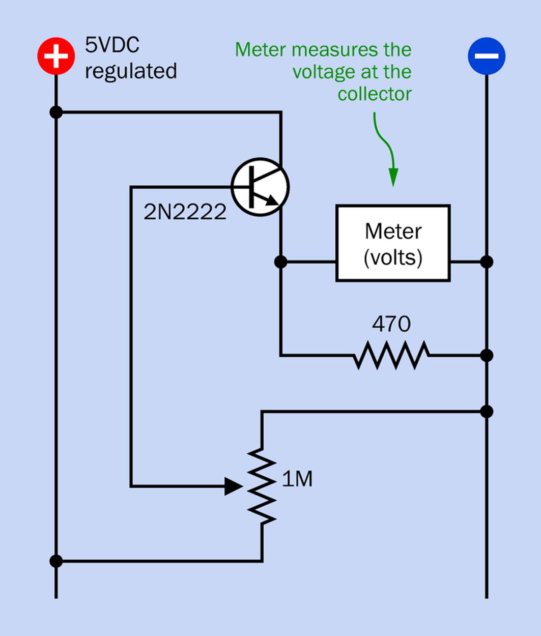
Figure 2-8. In this configuration, the meter measures voltage between the emitter of the transistor and the negative side of the power supply (so long as you remember to set the meter to measure voltage rather than current).
In Figure 2-6, the fifth column shows the measurements I made of voltages. I used these numbers to draw another graph, shown in Figure 2-9, comparing base current with emitter voltage—and once again, it’s a fairly straight line.
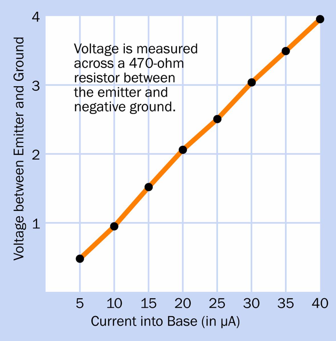
Figure 2-9. Emitter voltage varies almost linearly with base current, in a 2N2222 transistor. This graph was derived from numbers in the table shown previously.
If a transistor is a current amplifier, how come it is changing the voltage on its emitter, as well as the current? Well, let’s think about what is really happening inside the transistor:
§ An increase in the base current causes a reduction in the effective internal resistance of the transistor. This is why the current flowing through the transistor increases.
§ But the transistor is in series with the 470-ohm resistor. The two components create a kind of voltage divider.
Maybe you remember from Make: Electronics that when you have two resistances in series, they divide the voltage drop between them, depending on their resistance relative to each other. If the first resistor has a low value, it doesn’t block much voltage, so the second resistor imposes a bigger drop—and vice versa.
Take a look at Figure 2-10. In this schematic, instead of using a transistor in series with a 470Ω resistor, I’ve used various other resistors. Can you predict the voltages that will be measured at points A, B, C, and D? This is an experiment that you can perform for yourself very quickly. I’ll provide the theoretical answers at the end of this section of the book.
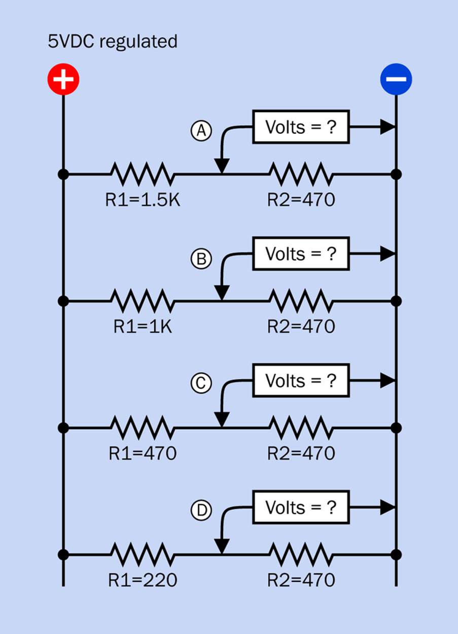
Figure 2-10. The concept of a voltage divider is fundamental in electronics. Make sure that you understand it clearly.
I’ll remind you of the formula for calculating the voltage at the midpoint between two resistors. In the formula:
§ VM is the voltage at the midpoint.
§ VCC is the supply voltage.
§ R1 is the value of the resistor (in ohms) on the positive side.
§ R2 is the value of the resistor (in ohms) on the negative side (as in Figure 2-10).
The relationship looks like this:
VM = VCC * (R2 / (R1 + R2) )
Perhaps now you see why the voltage at the emitter of the transistor goes up when the base current increases, in the circuit in Figure 2-8. The base current reduces the effective internal resistance of the transistor. Therefore, the transistor imposes less effective resistance between the emitter (where you are making your voltage measurement) and the positive power supply. Consequently, the voltage that you measure increases. This is shown in Figure 2-11.
The voltage at the emitter can never exceed the supply voltage. Similarly, the voltage applied to the base of the transistor will always be somewhere between 0 volts and the supply voltage. Why? Because the base voltage is taken from the 1M potentiometer, which acts as another voltage divider, between the positive and negative sides of the power supply.
Because the voltage at the emitter cannot exceed the voltage at the base, we can conclude that a bipolar transistor does not amplify voltage.
However, variations in emitter voltage can be useful, as you’ll see when you start using a phototransistor in Experiment 3.
Quick Facts About Voltage
So far I have made some assumptions without justifying them. I have assumed:
§ The positive voltage in a circuit is a fixed quantity.
§ All the points in a circuit wired directly to the negative side of the power supply have a potential of 0 volts.
§ Simple arithmetic defines the behavior of a voltage divider.
§ We can measure volts or milliamps anywhere we like, without disturbing the circuit.
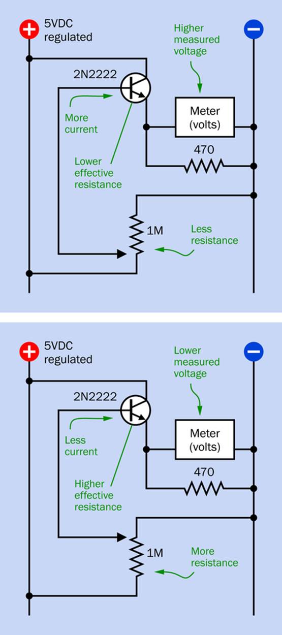
Figure 2-11. The consequences of more current (upper schematic) and less current (lower schematic) flowing through the base of an NPN transistor.
In the real world, these assumptions are not quite true!
VCC may be less than VCC
Any power source has its limits. When you load it heavily with a component of low resistance, this can pull down the voltage. The LM7805 regulator does a good job of fighting this tendency, but it is not perfect.
Zero may be greater than zero
We think of ground as being at 0 volts, but various components are sinking current into the ground connection, and the wire running back to the power source has a small resistance of its own. Depending where you make a connection with the ground wire, the ground potential may not be precisely zero relative to the negative side of the power source.
Voltage dividers are approximate
The voltage at the midpoint will be thrown off significantly if you attach a component that has a relatively low resistance and sinks current into the voltage divider, or draws current from it.
Measuring affects measurement
Even the process of measuring voltage (or current) can affect the values that you measure, because your meter itself has an internal resistance. This is very high, but not infinite, when measuring volts. It’s very low, but greater than zero, when measuring current. If your meter’s internal resistance is different from mine, the values that you and I measure won’t be exactly the same.
Make Even More: Old-School Metering
Now, for those who love gadgets (as I do), here’s the best possible way to redo Experiment 2.
Long before the invention of multiranging, multifunction meters, you could buy analog meters that did only one thing. They would measure volts or millivolts or amperes or milliamperes, within a fixed range. In fact you can still buy this kind of meter, and you can install a pair of them in your transistor testing circuit, so that you don’t have to move your multimeter to and fro.
Through eBay, I was able to order some nice little meters from Hong Kong for only $5 each. (You can also find them on Amazon for slightly more money, but with quicker shipping.) I chose one that measured microamperes on a scale of 0 to 50, while the other measured milliamperes on a scale of 0 to 10. These ranges were exactly what I needed. I set up the meters as shown in Figure 2-12. I enjoyed watching the needles move to and fro, perfectly synchronized, as I adjusted the trimmer potentiometer. Maybe this isn’t everyone’s idea of fun on a Saturday night (or even on a Monday night), but it makes a nice demo.
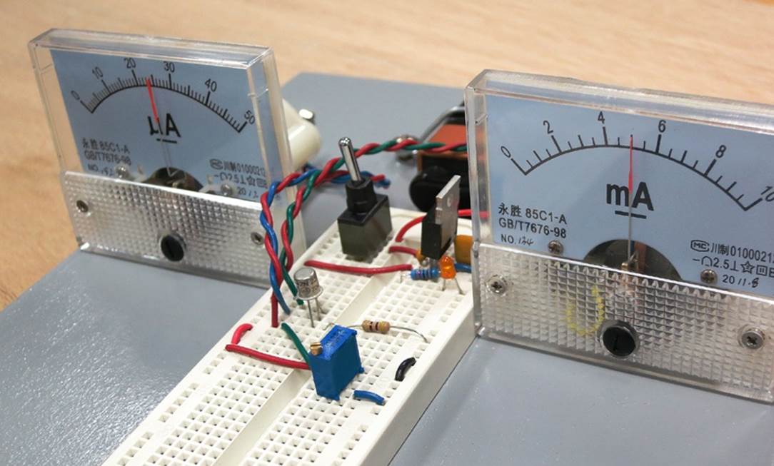
Figure 2-12. Two analog meters can give an immediate display of the current amplification capability of a basic 2N2222 bipolar transistor. The rectangular blue component in the foreground is a trimmer potentiometer with screw adjustment.
Quick Facts About Transistors
Some people enjoy working with numbers. Some don’t. I realize it may be more fun just to throw some components together and see what happens (with or without some Elmer’s glue), but the further you go into electronics, the more important it is to know what’s really going on, and for this purpose, you need some arithmetic. This is not very onerous, because in a DC circuit, you seldom do anything more difficult than multiplication and division. In an AC circuit, real mathematics is involved—but that’s beyond the scope of this book.
Here are your must-remember, take-home messages from this simple demo:
§ A bipolar transistor is a linear device, meaning that the ratio of current entering the collector to current entering the base is approximately constant, and a graph of these two variables is almost exactly a straight line.
§ The beta value of a transistor is its amplification factor—the ratio of the current flowing in at the collector, to current flowing in at the base.
§ The voltage on the emitter of an NPN bipolar transistor will vary with the current, so long as the emitter has a constant load on it.
§ A bipolar transistor is not a voltage amplifier, because the voltage at the emitter cannot exceed the voltage at the base.
And now a few additional facts:
§ The forward bias applied to an NPN transistor is positive voltage at the base, relative to voltage at the emitter. Negative bias would mean that the base has a lower voltage than the emitter. Try to avoid this, because it’s bad for the transistor.
§ The cutoff region is where VBE (the forward bias) is less than about 0.6 volts. In this region, charge carriers inside the transistor are not sufficiently energized, and nothing happens. Only a tiny amount of current, known as leakage, passes through the component when it is insufficiently forward-biased. This allows a transistor to be used as a switch.
§ The active region for a bipolar transistor is the range where it functions as a current amplifier. The upper limit of this region is where the effective internal resistance between collector and emitter drops so low, there is almost no limit to the current flowing between them. This is the saturation region in which overheating will occur.
Of course, a transistor may also overheat in the active region if you don’t limit the current. Always include some resistance (either a resistor or some other component that has resistance) with the transistor. Never apply the two sides of a power supply directly to the collector and the emitter.
Datasheets may have terms such as VCE(SAT) to tell you where the saturation limits are. Datasheets can be frustrating—for example, when they forget to define a term, or they don’t bother to include a schematic to show you how a component is typically used. Still, datasheets are essential if you decided to be creative and modify circuits or build your own. When you use a component for the first time, it’s a very good idea to go online, find the datasheet, and print a copy for future reference.
Answers to Voltage Divider Examples
1. 5 * (470 / 1970) = about 1.2V
2. 5 * (470 / 1470) = about 1.6V
3. 5 * (470 / 940) = 2.5V
4. 5 * (470 / 690) = about 3.4V
So much for the numbers. Now it’s time to play with light.
All materials on the site are licensed Creative Commons Attribution-Sharealike 3.0 Unported CC BY-SA 3.0 & GNU Free Documentation License (GFDL)
If you are the copyright holder of any material contained on our site and intend to remove it, please contact our site administrator for approval.
© 2016-2026 All site design rights belong to S.Y.A.