Make: More Electronics (2014)
Appendix B. Shopping for Parts
Depending on your budget and your preferences, you have four different ways to acquire components for the experiments in this book:
1. Minimum Shopping. If you disassemble every project after completing it, you can economize on the cost of components by reusing them. The Minimum Shopping list assumes that you’ll proceed on this basis. You will be recycling almost everything. SeeMinimum Shopping: Experiments 1 Through 14.
2. Moderate Shopping. If you don’t need to keep the test experiments, but you may want to retain a few finished projects that can be fun to play with, the Moderate Shopping List contains the parts that I think you are most likely to require. See Moderate Shopping: Experiments 1 Through 14.
3. Maximum Shopping. This list contains every component required to build and keep every item in each of the thirty-six experiments. The list also contains additional spare parts of the types that are most easily damaged or likely to burn out. See Maximum Shopping, Experiments 1 Through 14.
4. Incremental Shopping. If you prefer to buy parts in small quantities, or if you just want to check that you have what you need for a particular project, the Incremental Shopping list itemizes components for one experiment at a time. See Incremental Shopping.
The first three options (Minimum, Moderate, and Maximum Shopping) are subdivided into separate summaries for experiments 1 through 14, experiments 15 through 25, and experiments 26 through 36.
The Kit Option
Component kits will be available for this book. They are compiled on the same basis as if you were doing Moderate Shopping as defined above. For information, see http://www.makershed.com.
Sources
For people who prefer to buy their own components rather than use a kit, there are two main sources:
Online retailers
The most important rule is, be willing to try more than one source. Personally, the places where I look for parts online are:
§ http://www.mouser.com
§ http://www.radioshack.com
§ http://www.jameco.com
§ http://www.newark.com
§ http://www.digikey.com
§ http://www.alliedelec.com
§ http://www.allelectronics.com
§ http://www.sparkfun.com
If one of those retailers has sold out of a component, a competitor will often have it.
Bear in mind that http://www.allelectronics.com is primarily a discount source for surplus components and doesn’t have a huge, comprehensive stock. RadioShack, Jameco, and Sparkfun are hobbyist oriented, which means they are more likely to have the kinds of things we’re interested in. Still, they don’t have the amazingly diverse inventory of Mouser, Newark, or Digikey.
I realize that searching online takes time, even when you filter the results. This is why you should also have at least one paper catalog. The Mouser catalog, in particular, has a good index and is quicker to browse than the web site. The Jameco catalog is much smaller, but I find it useful because I often run across suggestions for parts that I didn’t consider.
Both Mouser and Jameco offer their catalogs free to serious customers.
Buy it now
eBay is a great place to find parts that are obscure or obsolete. It’s also a good source for state-of-the-art items, such as the latest LED lighting modules. And, it sells generic parts such as LEDs or resistors in bulk.
Don’t be afraid to buy from Asian vendors that ship via international airmail. I have ordered from China, Cambodia, and Thailand without any problems. The descriptions are accurate, the prices are low, and the airmail service is usually reliable, although you will have to wait about two weeks for delivery.
Generic Components
In the shopping lists, you will find that I don’t bother to specify precisely which type of LED to buy, or the brand of resistor, because they have become generic. Also I don’t bother to specify the working voltage for each capacitor, because in this book, we don’t need any capacitors rated above 16VDC.
Here’s what you need to know to do your own buying.
Resistors
Any manufacturer is acceptable. Lead length is unimportant. Quarter-watt power rating (the most common value) is acceptable. Eighth-watt power rating allows a smaller component, but check each application to make sure the resistor will not be overloaded. Some people may find eighth-watt resistors too small to work with conveniently, while half-watt resistors take up an inconvenient amount of space on a breadboard.
A tolerance of 10% is acceptable, and the color bands on 10% resistors are easier to read than the bands on 5% or 1% resistors. However, you can buy 1% resistors if you wish.
Figure B-1 shows the value multipliers that are common in electronics for capacitors and resistors. For instance, resistor values of 1K or 1.5K are common, and so are 10K or 15K, and 100Ω or 150Ω. The mulipliers shown in black in the table are less common.

Figure B-1. The traditional multipliers for resistor and capacitor values are shown in white along the top row. The additional black numbers show the full range of values for 5% resistors.
Long ago, many resistors and almost all capacitors had an accuracy of plus-or-minus 20%, and therefore, a 1K resistor could have an actual resistance as high as 1 + 0.2 = 1.2K, while a 1.5K resistor could have a resistance as low as 1.5 – 0.3 = 1.2K. Therefore, it made no sense to have a 20% resistor with an intermediate value of, say, 1.4K, because its actual value could overlap with the actual value of a 1K resistor. Conversely, if there was a value of 1.7K instead of 1.5K, this could result in a gap in the range of values.
The six values in white type, in the top row of the table in Figure B-1, were the original multipliers for values of 20% components. They are still the most widely used values today, even though 5% resistors have become common. The additional 5% multipliers are shown in black type.
For most projects, you don’t need all those 5% values. You can just stick to the six multipliers shown in white. I have used them exclusively throughout the book, so that you don’t have to buy an unnecessarily large variety of resistors.
Figure B-2 shows the values that you might aim to acquire for a stockpile of resistors. The quantities in the table will be sufficient for all of the projects in this book, plus at least 50%. If you’re wondering why the 220Ω and 10K values are so much more numerous than the rest, it’s because 220Ω is commonly used as a series resistor with an LED, and 10K is commonly used for a pullup or pulldown resistor on an input pin of a logic chip.
§ You may spend less money buying prepackaged assortments than if you try to buy small numbers of parts with specific values. The price of resistors drops radically when you buy them in bulk.
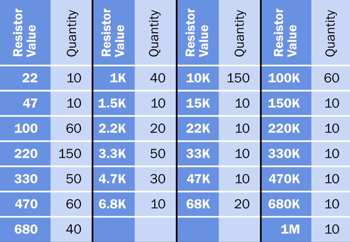
Figure B-2. The table shows quantities of resistors sufficient for all the projects in this book, plus at least 50%. All values are in ohms, except where otherwise indicated (K=kilohms; M=megohms).
Of course, you don’t have to buy the exact quantities shown in the table. You may be able to find a prepackaged assortment that matches the resistance values in the table and provides you with ten of each. You can then add the larger quantities separately.
Capacitors
Any manufacturer is acceptable. Radial leads are preferred. A working voltage of 16VDC is the minimum. Higher working voltages are acceptable. Multilayer ceramic capacitors are preferred. For capacitance values above 10µF, ceramics become more expensive and electrolytics are acceptable.
Figure B-3 suggests an assortment of capacitors to have in stock, sufficient for all of the projects in this book plus at least 50%. Try to use ceramic capacitors for the first three columns of values in the table. Purely for financial reasons, you’ll probably want to use electrolytics for values above 10µF.
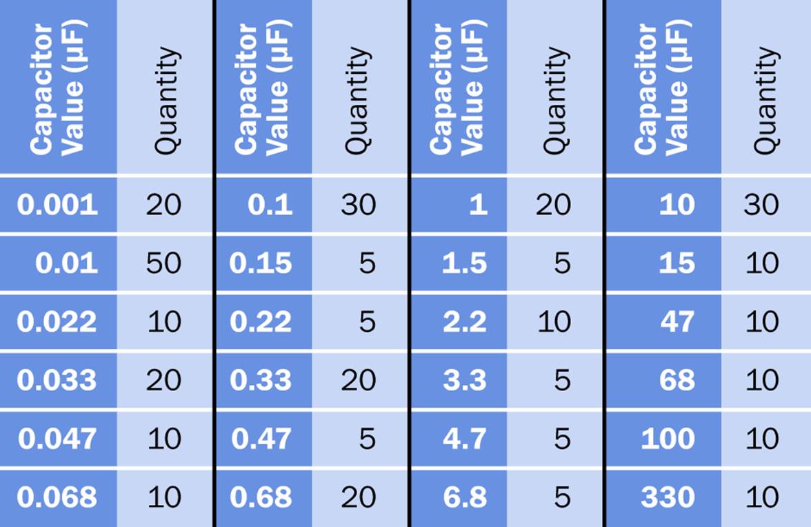
Figure B-3. A recommended range of capacitor values to have on hand, sufficient for all the projects in this book plus at least 50%.
Remember that 0.001µF = 1nF. I have avoided the nF (nanofarad) unit in the schematics in this book, because while it is common in Europe, it is less widely used in the United States.
Multilayer ceramic capacitors have become radically smaller and cheaper since the 1990s, and their durability makes them an attractive choice. Electrolytic capacitors are larger than the equivalent ceramic capacitors and may have a shorter shelf life, although this is a matter for debate.
Many authorities warn that electrolytics deteriorate with age because they have to be connected with a power source periodically to activate their internal chemistry. Yet I have electrolytics here which have been in storage for 15 years, and when I use them, they still seem to work. Should I trust the experts, or my own experience? I’m not sure, but with ceramic capacitors, the issue does not arise.
One problem with ceramic capacitors is that they seldom have any information printed on them. You can check their capacitance with your multimeter, if it offers this feature, but many meters cannot measure values higher than 20µF, and a meter cannot tell you the working voltage for which a capacitor is rated.
You have to be careful to label the storage containers for these components, and after you’ve taken one out of storage and used it in a project, you are unlikely to remember what its voltage rating is. For this reason, buying all your capacitors with the same voltage rating is helpful. A working voltage of 16VDC is the acceptable minimum, bearing in mind that capacitors should not generally be used at more than three-quarters of their rating.
LEDs
Any manufacturer is acceptable. LEDs come in a dizzying variety of shapes and sizes, but the type that is commonly described as “standard through hole” is what you want.
Often in this book you’ll find that I use LEDs to test a circuit and verify the outputs. You’ll find that 3mm diameter LEDs are useful for this purpose, as you can fit a series of them into adjacent rows on your breadboard.
§ 3mm LEDs are also referred to as being T-1 size.
Choose your own color, intensity, viewing angle, clear or diffused. Maximum forward current of 10mA is preferred for driving LEDs from 74HC00 series chips. Forward voltage of 2VDC is typical.
LEDs fitting this specification are Kingbright WP132X*D, where a letter specifying the color is substituted for the asterisk—for example, WP132XGD is the green one. Vishay TLHK4200 is comparable. LEDs of this general type should cost 15 cents or less in the US. You can get much better prices if you buy in bulk.
As test indicators, low-power LEDs that use a forward current of 2mA can be useful to prolong battery life. The relatively low light output will not be an issue when you simply want to verify that something is working.
LEDs with internal resistor
This type of component contains an internal resistor with the correct value for a specified supply voltage so that an external resistor is not needed. These are extremely convenient for breadboarding work and are strongly recommended if you are willing to pay about twice the price of regular LEDs. Vishay TLR*4420CU, where a letter specifying the color is substituted for the asterisk, is an example, rated for 12VDC but can be used with 9VDC or 5VDC. Chicago 4302F1-12V, 4302F3-12V, and 4302F5-12V (red, amber, and green, respectively) are acceptable but may be slightly more expensive.
Avago HLMP-1620 and HLMP-1640 series are rated for 5VDC. Personally I buy LEDs rated for 12VDC, because I’m not very interested in their brightness for testing purposes, and the 12VDC type can be used in both 9V and 5V circuits.
§ Where I specify a “generic” LED in the shopping lists, this means it is the everyday type that does not have an internal resistor and must be protected with an external resistor.
Warning: Series Resistors
Most of the photographs of breadboarded circuits in this book show LEDs with internal resistors and no external series resistors. If you use a generic LED, you must remember to add your own series resistor.
If an LED does not have an internal series resistor, a 470Ω resistor in 9VDC circuits and a 220Ω resistor in 5VDC circuits should be appropriate. Quarter-watt series resistors can be used if we assume a maximum voltage drop across the resistor of 7V at 15mA, in a 9V circuit. This will entail a power dissipation of about 100mW, which is less than half the wattage for which the resistor is rated.
If there’s a circuit that you want to build as a finished project, you may wish to use larger, brighter LEDs. Because specifications vary, it will be up to you to choose an appropriate series resistor to limit the current through the LED in accordance with the specification in the datasheet.
Chip Family Basics
Any manufacturer is acceptable. The “package” of a chip refers to its physical size, and this attribute should be checked carefully when ordering. All logic chips must be in a DIP package (meaning a dual-inline package with two rows of pins that have 0.1” spacing). This may also be referred to as PDIP (meaning a plastic dual-inline package). They are also described as “through hole.” The DIP and PDIP descriptors may be appended with the number of pins, as in DIP-14 or PDIP-16. The numbers can be ignored.
Surface-mount chips will have packaging descriptors beginning with S, as in SOT or SSOP. Do not buy any chips with “S” type packages. You won’t be able to use them.
The recommended chip family is HC (high-speed CMOS), as in 74HC00, 74HC08, and similar generic identifiers. These numbers will have additional letters or numbers added by individual manufacturers as prefixes or suffixes, as in SN74HC00DBR (a Texas Instruments chip) or MC74HC00ADG (from On Semiconductor). For our purposes, these versions are functionally identical. Look carefully, and you will see the 74HC00 generic number embedded in each proprietary number.
Sources often state that an HC chip can source or sink a maximum of 4mA to 6mA, but information from manufacturers (such as Application Note 313 from Fairchild Semiconductor) explicitly states that sourcing up to 25mA will not damage an HC series chip.
However, if the output of a logic chip is driving the input of another chip in addition to an LED, 10mA is a safer current value because the voltage on the output of a logic chip is pulled down by higher currents. If the voltage drops below 3.5VDC, another logic chip may fail to recognize this as a high state. A minimum of 4VDC is preferable.
Logic chips can be found in vendor sites by searching just for the generic number (e.g., 74HC86 for a quad two-input XOR chip). Generally speaking, the additional manufacturers’ letters or numbers can be ignored, so long as the chip is specified to work with a 5VDC power supply. Often the specification will state “2V to 6V” for the HC series chips.
In some instances, the old 4000B series of logic chips may have functions that are unavailable in the 74HC00 family. For instance, a four-input OR gate is unavailable in the HC series, but the 4072B contains two four-input OR gates.
The 4000B series of logic chips can be substituted for 74HC00 series chips if their lower sourcing or sinking output current is acceptable. Most 4000B series logic chips are designed to interface with other chips, not with LEDs.
Figure B-4 shows the input and output voltage ranges that are interpreted as high and low logic states in the 4000B series and the 74HC00 series. You can see that these families of chips should have no problem understanding each other.
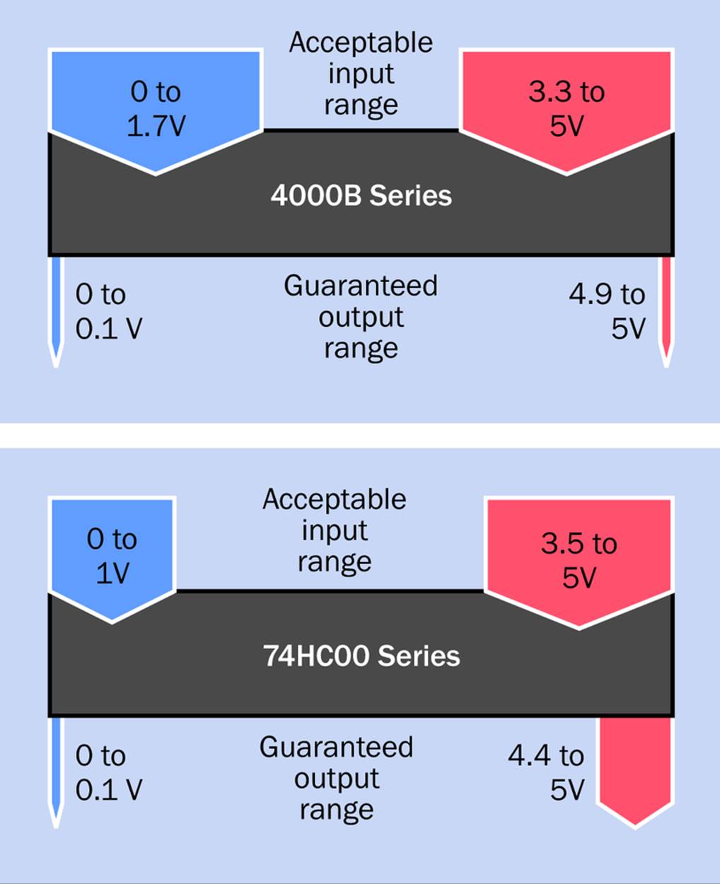
Figure B-4. Acceptable input voltages and guaranteed output source-or-sink voltages for logic chips in the 4000B and 74HC00 families. The output voltages are specified assuming an output current of 4mA (for 74HC00 chips) and 0.5mA (for 4000B chips). Higher current values will pull down the voltages.
TTL logic chips, such as the 74LS00 series, have significant compatibility issues. They are not used or recommended for any of the projects in this book.
Transistors
For convenience, only one type of transistor is used in this book: the 2N2222. This generic part number is often preceded by manufacturers with a P, as in PN2222, or PN2222A, or PN2222ATFR. The letters at the beginning of the part number make no difference.
Be careful not to buy a P2N2222, even if an online supplier’s search algorithm suggests it as a substitute. In the case of this component, the letter and numeral (P2) make a big difference. The P2N2222 has pin functions that are reversed from all the other types. This can cause confusion, frustration, and a lot of wasted time.
Switches
Four types of switch are frequently used in the projects in this book: tactile switches, pushbutton switches, DIP switches, and toggle switches.
Tactile switches are very small pushbuttons that can be inserted in breadboards (or perforated boards, if you wish). The manufacturer and part number are generally irrelevant, so long as the switch is “through-hole” type, not surface mount. Its pins must fit a breadboard that has rows spaced at 0.1”.
The most common tactile switches are 6mm x 6mm in size (about 1/4” square), often referred to as 6x6 in parts catalogues. They have four pins, but each pair of pins is typically joined together inside the switch so that this is a SPST device even though it looks as if it might have two poles.
For projects in this book, I prefer a half-size tactile switch, often described as being 3.5mm x 6mm in size. It has only two pins and occupies only one column on your breadboard. Examples are the Mountain Switch TS4311T series, with actual part numbers such as TS4311T5201 or TS4311T1601. These are different from each other only in the color of the button and the pressure that has to be applied to close the switch contacts.
Pushbutton switches of the type used in several projects here are DPDT, 4PDT, or 6PDT, depending on the application. They can be momentary switches that revert to their initial state when you let go of the button, or push-twice switches, also known as latching switches, where you press the button a second time to get back to the initial state.
This is really a matter of individual preference, and you can make up your mind when you read a description of a project and see how it is intended to be used. Any brand of pushbutton switch is acceptable, but they must be “through-hole” type with solder pins, and you should try to obtain them with 0.1” pin spacing (often listed as 2.54mm, although 2.5mm is acceptable). The Alps SPUJ series is typical. The E-Switch PBH series may also be used, such as the PBH4UOANAGX, where the number 4 identifies it as a four-pole switch.
Note that most pushbutton switches are sold without caps or buttons. You are expected to choose them separately. This allows you various options for color, shape, and size.
DIP switches are dual-inline pin format to fit across the center channel of your breadboard. The number of “positions” actually refers to the number of separate miniature switches in the component. Each should be SPST. The component must have a pin spacing of 2.54mm or 0.1”, and must be described as “through-hole” or “PCB mount” or “solder pin” to fit your breadboard.
The BD series by C&K switches is typical, with the part number telling you how many “positions” (switches) each component has. Thus the BD02 has two positions, BD04 has four positions, and so on.
Toggle switches are used in this book only to switch the 5VDC or 9VDC power supply. You need an SPST or SPDT switch described as being “through hole,” or having solder pins, or being suitable for PC board mounting, so long as the pin spacing is 0.1” (2.54mm) or 0.2” (5.08mm). Mountain Switch 108-2MS1T2B3M2QE-EVX is an example. The toggle switches in the projects described here will not be heavily used, so you can buy the smallest and cheapest you can find.
Power Supply, Breadboards, and Wiring
Each project requires either a 9VDC supply (which can be provided by a 9V battery) or a 5VDC regulated power supply. See Setup for details.
If you expect to keep some projects in their final form, I leave it to you to decide how many power supplies you need. Don’t forget to buy a snap-on connector for each 9V battery.
You will require between two and thirty breadboards, depending how many breadboarded projects you decide to keep. (A couple of projects are too big to fit on a single breadboard, so they require a pair; this is why the minimum number of breadboards is two.) The type of breadboard that I am recommending is very affordable if you buy them from Asian vendors through eBay. I have seen them at five for $10, with free shipping.
Setup also discusses hookup wire and jumpers.
So much for the procurement information. Now, here are the lists.
Minimum Shopping: Experiments 1 Through 14
See Generic Components above for guidance about purchasing generic components including resistors, capacitors, LEDs, logic chips, transistors, and switches.
All quantities in the following lists are shown in parentheses. If no quantity is listed, the quantity is 1:
Power
§ 1.5V battery (2)
§ 9V battery and connector
§ One 5VDC voltage supply requires an LM7805 voltage regulator, plus two capacitors, a resistor, and an LED, which are included below.
§ AC adapter with 10VDC to 12VDC for long-term installation of Experiment 7
Resistors
§ 22Ω, 47Ω, 100Ω, 220Ω (2), 470Ω (5), 1K (3), 1.5K, 2.2K (10), 3.3K, 4.7K (2), 10K (4), 33K, 68K (2), 100K (10), 150K (2), 220K (2), 1M (2)
Capacitors
§ 0.01µF(2), 0.047µF, 0.068µF, 0.1µF (3), 0.33µF (3), 0.68µF (2), 1µF (5), 10µF (3), 15µF, 47µF, 100µF, 220µF, 330µF
Switches
§ Toggle (SPST or SPDT)
§ Tactile
LEDs
§ 3mm generic (4)
Trimmer potentiometers
§ 5K, 10K, 500K (2), 1M
Transistors
§ 2N2222 or PN2222 (3)
Integrated circuit chips
§ 555 timer, old-style bipolar type (2)
§ LM339 comparator
§ LM741 op-amp
§ LM386 power amp
Sensors
§ Phototransistor PT334-6C or similar, responsive to white light
§ Microphone (electret, generic, two-terminal type)
Audio output
§ Loudspeaker, 2” diameter, 50Ω or higher
§ Beeper, 9VDC or 12VDC, 100mA max.
Other
§ Alligator clip (2)
§ Patch cord with alligator at each end (3)
§ Corrugated cardboard, minimum 6” x 12” (1 piece)
§ Elmer’s glue or similar white glue (minimal quantity)
§ LM7805 voltage regulator
§ LM7806 voltage regulator
§ UA78M33 voltage regulator
§ 1N4001 small rectifier diode (2)
§ Latching relay DS1E-SL2-DC3V or similar in SPDT or DPDT format with 3VDC coil to switch up to 2A
§ Battery-powered digital alarm clock must use two 1.5V batteries
Minimum Shopping: Experiments 15 Through 25
See Generic Components above for guidance about purchasing generic components including resistors, capacitors, LEDs, logic chips, transistors, and switches.
All quantities in the following lists are shown in parentheses. If no quantity is listed, the quantity is 1:
§ I assume that you have previously bought the components listed for Minimum Shopping: Experiments 1 through 14, and you have those components available to you for reuse in experiments 15 through 25. The quantities listed below are therefore additional to those which you already have.
Resistors
§ 100Ω (9), 220Ω (8), 330Ω (6), 470Ω (2), 3.3K, 10K (15)
Capacitors
§ 0.001µF (2)
Switches
§ Tactile (5)
§ Pushbutton SPDT
§ Pushbutton DPDT (3)
§ Pushbutton 4PDT (6)
§ Pushbutton 6PDT (2)
§ Cap for pushbutton (9)
§ DIP 4-position (2)
§ DIP 8-position (2)
LEDs
§ 3mm generic (16)
Trimmer potentiometers
§ 1K, 50K
Integrated circuit chips
§ 74HC08 quad two-input AND (2)
§ 74HC32 quad two-input OR
§ 74HC02 quad two-input NOR
§ 74HC86 quad two-input XOR (2)
§ 74HC4075 triple three-input OR
§ 74HC4002 dual four-input NOR
§ 74HC4514 decoder or 4514B decoder
§ 74HC237 decoder (2)
§ 4067B multiplexer
§ 4520B counter
§ 74HC148 encoder (2)
§ 74HC11 triple three-input AND
Sensor
§ Phototransistor PT334-6C or similar, responsive to white light
Audio output
§ Buzzer or beeper, 9VDC or 12VDC (2)
§ Loudspeaker 2” diameter, 50Ω or higher
Other
§ Plain perforated board with no copper traces (6” x 6” piece minimum)
Optional extras
§ Multicolored ribbon cable (2 feet)
§ Pushbutton 3PDT
§ Pushbutton DPDT (3)
§ Pushbutton SPDT (3)
§ Caps for pushbuttons (7)
Minimum Shopping: Experiments 26 Through 36
See Generic Components above for guidance about purchasing generic components, including resistors, capacitors, LEDs, logic chips, transistors, and switches.
All quantities are shown in parentheses. If no quantity is listed, the quantity is 1:
§ I assume that you have previously bought the components listed for Minimum Shopping experiments 1 through 14 and 15 through 25. Those components should be available to you for reuse in experiments 26 through 36. The quantities listed below are thereforeadditional to those which you already have.
Resistors
§ 220Ω (14), 100K (2)
Capacitors
§ 47pF, 68pF, 100pF, 0.0001µF, 0.01µF (2), 0.033µF, 2.2µF
LEDs
§ 3mm generic (25), or (10) if light bars (36) are used in Experiment 28
§ 5mm generic (16)
Trimmer Potentiometers
§ 1K, 2K, 100K
Integrated circuit chips
§ 7555 timer (3)
§ 74HC4017 counter (3)
§ 74HC164 shift register (3)
§ 4078B single eight-input OR/NOR
§ 74HC7266 quad two-input XNOR
§ 74HC30 single eight-input NAND
Sensors
§ SPST reed switch, any type
§ Bipolar Hall-effect sensor, ATS177 or similar, and unipolar, or linear, or omnipolar Hall-effect sensor (optional)
§ Transmissive infrared sensor Everlight ITR9606 or similar
§ Thermistor 100K
§ Bourns ECW1J-B24-BC0024L rotational encoder or similar with 24PPR and 24 detents and quadrature output (2)
Other
§ Flexible jumper wires (35)
§ Small iron bar magnet approximately 1/4” x 1/4” x 1.5” or very small neodymium bar magnet approximately 1/4” x 1/16” x 1/2”
§ Lead sinkers (2) and galvanized wire (1 foot) as described in Experiment 33
Optional extras
§ Header pins (33)
§ Header sockets (33)
§ Light bars (36) and ULN2003 Darlington array (3) if making a finished version of Experiment 28
§ Ball magnet and aluminum tube, and ring magnets (4) as described in Experiment 29
§ 330Ω (16), 680Ω (16), 3.3K (16), 5mm LED (16), Transmissive infrared sensor Everlight ITR9606 or similar (16), and ULN2003 Darlington array (3) if making a finished version of Experiment 31
Moderate Shopping: Experiments 1 Through 14
See Generic Components above for guidance about purchasing generic components including resistors, capacitors, LEDs, logic chips, transistors, and switches.
All quantities in the following lists are shown in parentheses. If no quantity is listed, the quantity is 1:
Power
§ 1.5V battery (2)
§ 9V battery and connectors (5 max)
§ AC adapter with 10VDC to 12VDC fixed output at 1A minimum
§ 5VDC voltage supply; requires the following (multiply by the number of projects for which you will want to use a separate supply):
§ LM7805 voltage regulator
§ 2.2K resistor
§ 0.33µF, 0.1µF capacitor
§ Toggle switch SPST or SPDT
§ Generic 3mm LED
Resistors
§ 22Ω (5), 47Ω (5), 100Ω (5), 220Ω (5), 470Ω (10), 1K (10), 1.5K (5), 2.2K (10), 3.3K (5), 4.7K (5), 10K (15), 33K (5), 68K (5), 100K (20), 150K (5), 220K (5), 1M (5)
Because resistors are very inexpensive, the minimum quantity in this list is 5.
Capacitors
§ 0.01µF (10), 0.047µF (5), 0.068µF (5), 0.1µF (5), 0.33µF (5), 0.68µF (5), 1µF (5), 10µF (10), 15µF, 47µF, 100µF (2), 220µF, 330µF
Because ceramic capacitors with values below 10µF are very inexpensive, their minimum quantity in this list is 5.
Switches
§ Toggle
§ Tactile
LEDs
§ 3mm generic (10)
Trimmer potentiometers
§ 5K, 10K, 500K (4), 1M (3)
Transistors
§ 2N2222 or PN2222 (7)
Integrated circuit chips
§ 555 timer, old-style bipolar type (7)
§ LM339 comparator (3)
§ LM741 op-amp (3)
§ LM386 power amp
Sensors
§ Phototransistor PT334-6C or similar, responsive to white light (3)
§ Microphone, electret, generic, two-terminal type (4)
Audio output
§ Loudspeaker, 2” diameter, 50Ω or higher (3)
§ Buzzer or beeper, 9VDC or 12VDC, 100mA max
Other
§ Alligator clip (2)
§ Patch cord with alligator at each end (3)
§ Corrugated cardboard, minimum 6” x 12” (1 piece)
§ Elmer’s glue or similar white glue (minimal quantity)
§ LM7806 voltage regulator
§ UA78M33 voltage regulator
§ 1N4001 small rectifier diode (2)
§ Latching relay DS1E-SL2-DC3V or similar in SPDT or DPDT format with 3VDC coil to switch up to 2A
§ Battery-powered digital alarm clock; must use two 1.5V batteries
Optional extras
§ Distilled or deionized water
§ Table salt
Moderate Shopping: Experiments 15 Through 25
See Generic Components above for guidance about purchasing generic components including resistors, capacitors, LEDs, logic chips, transistors, and switches.
All quantities in the following lists are shown in parentheses. If no quantity is listed, the quantity is 1. This list is entirely self-contained and does not require any parts that may have been purchased for experiments 1 through 14:
Power
§ 9V battery and connectors
§ 5VDC voltage supply; requires the following (multiply by the number of projects for which you will want to use a separate supply):
§ LM7805 voltage regulator
§ 2.2K resistor
§ 0.33µF, 0.1µF capacitor
§ Toggle switch SPST or SPDT
§ Generic 3mm LED
Resistors
§ 100Ω (15), 220Ω (15), 330Ω (10), 470Ω (15), 1K (5), 3.3K, 4.7K, 10K (20), 33K (5)
Because resistors are very inexpensive, the minimum quantity in this list is 5.
Capacitors
§ 0.001µF (5), 0.01µF (5), 0.1µF (5), 100µF
Because ceramic capacitors with values below 10µF are very inexpensive, their minimum quantity in this list is 5.
Switches
§ Tactile (10)
§ Pushbutton DPDT (4)
§ Pushbutton 4PDT (12)
§ Cap for pushbutton (16)
§ DIP 4-position (2)
§ DIP 8-position (2)
LEDs
§ 3mm with internal resistors (35)
§ 5mm generic (10)
Trimmer potentiometers
§ 50K
Transistors
§ 2N2222 or PN2222
Integrated circuit chips
§ 555 timer old-style bipolar type (3)
§ 74HC08 quad two-input AND (4)
§ 74HC32 quad two-input OR (2)
§ 74HC02 quad two-input NOR
§ 74HC86 quad two-input XOR (4)
§ 74HC4075 triple three-input OR (2)
§ 74HC4002 dual four-input NOR
§ 74HC11 triple three-input AND
§ 74HC4514 decoder or 4514B decoder (2)
§ 74HC237 decoder (2)
§ 4067B multiplexer
§ 4520B counter
§ 74HC148 encoder (2)
Sensors
§ Phototransistor PT334-6C or similar, responsive to white light
Audio output
§ Buzzer or beeper 9VDC or 12VDC (3)
§ Loudspeaker 2” diameter, 50Ω or higher
Other
§ Plain perforated board with no copper traces (6” x 6” piece minimum)
Optional extras
§ Multicolored ribbon cable (2 feet)
§ Pushbutton 3PDT
§ Pushbutton DPDT (3)
§ Pushbutton SPDT (3)
§ Caps for pushbuttons (7)
Moderate Shopping: Experiments 26 Through 36
See Generic Components above for guidance about purchasing generic components, including resistors, capacitors, LEDs, logic chips, transistors, and switches.
All quantities in the following lists are shown in parentheses. If no quantity is listed, the quantity is 1. This list is entirely self-contained and does not require any parts that may have been purchased for experiments 1 through 25:
Power
§ 9V battery and connector
§ 5VDC voltage supply; requires the following (multiply by the number of projects for which you will want to use a separate supply):
§ LM7805 voltage regulator
§ 2.2K resistor
§ 0.33µF, 0.1µF capacitor
§ Toggle switch SPST or SPDT
§ Generic 3mm LED
Resistors
§ 100Ω (5), 220Ω (50), 330Ω (20), 470Ω (5), 680Ω (20), 1K (5), 3.3K (20), 4.7K (5), 10K (20), 100K (5), 1M (5)
Because resistors are very inexpensive, the minimum quantity in this list is 5.
Capacitors
§ 47pF (5), 68pF (5), 0.0001µF (5), 0.001µF (5), 0.01µF (10), 0.033µF (5), 0.1µF (5), 0.33µF (5), 1µF (5), 2.2µF (5), 10µF (5), 100µF
Because ceramic capacitors with values below 10µF are very inexpensive, their minimum quantity in this list is 5.
Switches
§ Tactile (2)
§ Pushbutton DPDT (4)
§ Cap for pushbutton (4)
LEDs
§ 3mm generic (40) or (4) if light bars (36) are used in Experiment 28
§ 3mm with internal resistor (40)
§ 5mm generic (20)
Trimmer potentiometers
§ 1K, 2K, 100K
Transistors
§ 2N2222 or PN2222 (2)
Integrated circuit chips
§ 7555 timer (8)
§ 74HC4017 counter (3)
§ 74HC08 quad two-input AND (2)
§ 74HC32 quad two-input OR (2)
§ 74HC86 quad two-input XOR (2)
§ 74HC7266 quad two-input XNOR (2)
§ 4078B single eight-input OR/NOR
§ 4520B binary counter
§ 74HC30 single eight-input NAND
§ 74HC164 shift register (5)
§ 74HC4514 decoder or 4514B decoder
§ 74HC4017 counter
§ ULN2003 Darlington array (2), or (5) if light bars are used in Experiment 28
Sensors
§ SPST reed switch, any type
§ Bipolar Hall-effect sensor, ATS177 or similar (2), and unipolar, or linear, or omnipolar Hall-effect sensor (optional)
§ Transmissive infrared sensor Everlight ITR9606 or similar
§ Thermistor 100K
§ Bourns ECW1J-B24-BC0024L rotational encoder or similar with 24PPR and 24 detents and quadrature output (2)
Other
§ Flexible jumper wires (50)
§ Small iron bar magnet 1/4” x 1/4” x 1.5” approx. or very small neodymium bar magnet 1/4” x 1/16” x 1/2” approx.
§ Lead sinkers (2) and galvanized wire (1 foot) as described in Experiment 33
Optional extras
§ Multicolor ribbon cable (2 feet)
§ Header pins (33)
§ Header sockets (33)
§ Light bars (36) and ULN2003 Darlington array (3) if making a finished version of Experiment 28
§ 330Ω (16), 680Ω (16), 3.3K (16), 5mm LED (16), Transmissive infrared sensor Everlight ITR9606 or similar (16), and ULN2003 Darlington array (3) if making a finished version of Experiment 31
§ Ball magnet and aluminum tube, and ring magnets (4) as described in Experiment 29
Maximum Shopping, Experiments 1 Through 14
See Generic Components above for guidance about purchasing generic components, including resistors, capacitors, LEDs, logic chips, transistors, and switches.
All quantities in the following lists are shown in parentheses. If no quantity is listed, the quantity is 1:
Power
§ 9V battery and connector (8 max)
§ AC adapter with 10VDC to 12VDC fixed output at 1A minimum
§ 5VDC voltage supply; requires the following (multiply by the number of projects for which you will want to use a separate supply):
§ LM7805 voltage regulator
§ 2.2K resistor
§ 0.33µF, 0.1µF capacitor
§ Toggle switch SPST or SPDT
§ Generic 3mm LED
Resistors
§ 22Ω (5), 47Ω (5), 100Ω (5), 220Ω (5), 470Ω (10), 1K (15), 1.5K (5), 2.2K (10), 3.3K (10), 4.7K (10), 10K (20), 33K (5), 68K (10), 100K (40), 150K (5), 220K (5), 1M (5)
Because resistors are very inexpensive, the minimum quantity in this list is 5.
Capacitors
§ 0.01µF (10), 0.047µF (5), 0.068µF (5), 0.1µF (5), 0.33µF (5), 0.68µF (10), 1µF (10), 10µF (15), 15µF (2), 47µF (3), 100µF (4), 220µF (2), 330µF (3)
Because ceramic capacitors with values below 10µF are very inexpensive, their minimum quantity in this list is 5.
Switches
§ Toggle
§ Tactile
LEDs
§ 3mm generic (10)
Trimmer potentiometers
§ 5K, 10K, 500K (4), 1M (3)
Transistors
§ 2N2222 or PN2222 (10)
Integrated circuit chips
§ 555 timer, old-style bipolar type (10)
§ LM339 comparator (5)
§ LM741 op-amp (7)
§ LM386 power amp
Sensors
§ Phototransistor PT334-6C or similar, responsive to white light (5)
§ Microphone, electret, generic, two-terminal type (5)
Audio output
§ Loudspeaker, 2” diameter, 50Ω or higher (5)
§ Buzzer or beeper, 9VDC or 12VDC, 100mA max.
Other
§ Alligator clip (2)
§ Patch cord with alligator at each end (3)
§ Corrugated cardboard, minimum 6” x 12” (1 piece)
§ Elmer’s glue or similar white glue (minimal quantity)
§ LM7806 voltage regulator
§ UA78M33 voltage regulator
§ 1N4001 small rectifier diode (2)
§ Latching relay DS1E-SL2-DC3V or similar in SPDT or DPDT format with 3VDC coil to switch up to 2A
§ Battery-powered digital alarm clock; must use two 1.5V batteries
Optional extras
§ Distilled or deionized water
§ Table salt, extra transistor
§ Ammeter (50 microamperes)
§ Ammeter (10 milliamperes)
Maximum Shopping: Experiments 15 Through 25
See Generic Components above for guidance about purchasing generic components, including resistors, capacitors, LEDs, logic chips, transistors, and switches.
All quantities in the following lists are shown in parentheses. If no quantity is listed, the quantity is 1. This list is entirely self-contained and does not require any parts that may have been purchased for experiments 1 through 14:
Power
§ 9V battery and connector (5 max)
§ 5VDC voltage supply; requires the following (multiply by the number of projects for which you will want to use a separate supply):
§ LM7805 voltage regulator
§ 2.2K resistor
§ 0.33µF and 0.1µF capacitor
§ Toggle switch SPST or SPDT
§ Generic 3mm LED
Resistors
§ 100Ω (20), 220Ω (40), 330Ω (10), 470Ω (15), 1K (5), 3.3K (5), 4.7K (5), 10K (60), 33K (5)
Because resistors are very inexpensive, the minimum quantity in this list is 5.
Capacitors
§ 0.001µF (5), 0.01µF (5), 0.1µF (5), 100µF (2)
Because ceramic capacitors with values below 10µF are very inexpensive, their minimum quantity in this list is 5.
Switches
§ Tactile (16)
§ Pushbutton DPDT (4)
§ Pushbutton 4PDT (18)
§ Pushbutton 6PDT (2)
§ Cap for pushbutton (25)
§ DIP 4-position (3)
§ DIP 8-position (4)
LEDs
§ 3mm generic (10)
§ 3mm with internal resistors (50)
§ 5mm generic (15)
Trimmer potentiometers
§ 50K
Transistors
§ 2N2222 or PN2222
Integrated circuit chips
§ 555 timer old-style bipolar type (3)
§ 74HC08 quad two-input AND (8)
§ 74HC32 quad two-input OR (4)
§ 74HC02 quad two-input NOR (2)
§ 74HC86 quad two-input XOR (6)
§ 74HC4075 triple three-input OR (3)
§ 74HC4002 dual four-input NOR (2)
§ 74HC11 triple three-input AND (2)
§ 74HC4514 decoder or 4514B decoder (3)
§ 74HC237 decoder (3)
§ 4067B multiplexer (2)
§ 4520B counter (2)
§ 74HC148 encoder (3)
Sensors
§ Phototransistor PT334-6C or similar, responsive to white light
Audio output
§ Loudspeaker 2” diameter, 50Ω or higher
§ Buzzer or beeper, 9VDC or 12VDC (3)
Other
§ Plain perforated board with no copper traces (6” x 6” piece minimum)
Optional extras
§ Multicolored ribbon cable (2 feet)
§ Pushbutton 3PDT
§ Pushbutton DPDT (3)
§ Pushbutton SPDT (3)
§ Caps for pushbuttons (7)
Maximum Shopping: Experiments 26 Through 36
See Generic Components above for guidance about purchasing generic components, including resistors, capacitors, LEDs, logic chips, transistors, and switches.
All quantities in the following lists are shown in parentheses. If no quantity is listed, the quantity is 1.
This list is entirely self-contained and does not require any parts that may have been purchased for experiments 1 through 25:
Power
§ 9V battery and connector (3 max)
§ 5VDC voltage supply; requires the following (multiply by the number of projects for which you will want to use a separate supply):
§ LM7805 voltage regulator
§ 2.2K resistor
§ 0.33µF, 0.1µF capacitor
§ Toggle switch SPST or SPDT
§ Generic 3mm LED
Resistors
§ 100Ω (5), 220Ω (70), 330Ω (20), 470Ω (5), 680Ω (20), 1K (5), 3.3K (20), 4.7K (5), 10K (25), 100K (10), 1M (5)
Because resistors are very inexpensive, the minimum quantity in this list is 5.
Capacitors
§ 47pF (5), 68pF (5), 0.0001µF (5), 0.001µF (5),, 0.01µF (15), 0.033µF (10), 0.1µF (5), 0.33µF (5), 1µF (5), 2.2µF (5), 10µF (5), 100µF (3)
Because ceramic capacitors with values below 10µF are very inexpensive, their minimum quantity in this list is 5.
Switches
§ Tactile (4)
§ Pushbutton DPDT (7)
§ Cap for pushbutton (7)
LEDs
§ 3mm generic (40) or (4) if light bars (36) are used in Experiment 28
§ 3mm with internal resistor (60)
§ 5mm generic (20)
Trimmer potentiometers
§ 1K, 2K, 100K
Transistors
§ 2N2222 or PN2222
Integrated circuit chips
§ 7555 timer (11)
§ 74HC4017 counter (3)
§ 74HC08 quad two-input AND (2)
§ 74HC32 quad two-input OR (2)
§ 74HC86 quad two-input XOR (3)
§ 74HC7266 quad two-input XNOR (2)
§ 74HC30 single eight-input NAND
§ 4078B single eight-input OR/NOR
§ 4520B binary counter (2)
§ 74HC164 shift register (6)
§ 74HC4017 counter (3)
§ 74HC4514 decoder or 4514B decoder
§ ULN2003 Darlington array (2) or (5) if light bars are used in Experiment 28
Sensors
§ SPST reed switch, any type (2)
§ Bipolar Hall-effect sensor, ATS177 or similar (2), and unipolar, or linear, or omnipolar Hall-effect sensor (optional)
§ Transmissive infrared sensor Everlight ITR9606 (20)
§ Thermistor 100K (2)
§ Bourns ECW1J-B24-BC0024L rotational encoder or similar with 24PPR and 24 detents and quadrature output (3)
Other
§ Flexible jumper wires (50)
§ Small iron bar magnet approximately 1/4” x 1/4” x 1.5” (2) or very small neodymium bar magnet approximately 1/4” x 1/16” x 1/2” (2)
§ Lead sinkers (2) and galvanized wire (1 foot) as described in Experiment 33
Optional extras
§ 3300Ω (16), 6800Ω (16), 3.3K (16), 5mm LED (16), Transmissive infrared sensor Everlight ITR9606 or similar (16), and ULN2003 Darlington array (3) if making a finished version of Experiment 31
§ Multicolor ribbon cable (2 feet)
§ Header pins (40) and header sockets (40)
§ Light bars (36) and ULN2003 Darlington array (3) if making a finished version of Experiment 28
§ Ball magnet and aluminum tube, and ring magnets (4) as described in Experiment 29
Incremental Shopping
See Generic Components above for guidance about purchasing generic components, including resistors, capacitors, LEDs, logic chips, transistors, and switches.
The following lists show the precise quantity of each component required for each experiment. The quantities are in parentheses. If no quantity is listed, the quantity is 1:
Experiment 1
Power
9V battery and connector
Resistor
470Ω
Transistor
2N2222 or PN2222
LED
Any type
Other
Alligator clip (2), patch cord with alligator at each end (3), corrugated cardboard, minimum 6” x 12” (1 piece), Elmer’s glue or similar white glue (minimal quantity)
Optional extras
Distilled or deionized water, table salt, extra transistor
Experiment 2
Power
5VDC regulated
Resistor
220Ω, 470Ω(5), 1K, 1.5K
Trimmer potentiometer
1M
Transistor
2N2222 or PN2222
Experiment 3
Power
5VDC regulated
Resistor
100Ω, 3.3K, 10K, 33K
Capacitor
0.01µF, 10µF
Integrated circuit chip
555 timer, old-style bipolar type
Sensor
Phototransistor PT334-6C or similar, responsive to white light
Audio output
Loudspeaker, 2” diameter, 50Ω or higher
Experiment 4
Power
5VDC regulated
Resistor
3.3K
Sensor
Phototransistor PT334-6C or similar, responsive to white light
Experiment 5
Power
5VDC regulated
Resistor
100Ω, 3.3K, 10K (2), 33K, 150K
Capacitor
0.01µF, 1µF, 10µF (2), 47µF
Integrated circuit chip
555 timer old-style bipolar type (2)
Sensor
Phototransistor PT334-6C or similar, responsive to white light
Audio output
Loudspeaker 2” diameter, 50Ω or higher
Experiment 6
Power
5VDC regulated
Resistor
470Ω, 3.3K, 100K
LED
Generic 3mm
Trimmer potentiometer
500K (2)
Integrated circuit chip
LM339 comparator
Sensor
Phototransistor PT334-6C or similar, responsive to white light
Experiment 7
Power
9V battery and connector for circuit testing, 1.5 battery to fit clock (2), AC adapter with 10VDC to 12VDC for long-term installation
Resistor
47Ω, 220Ω (2), 1K (2), 3.3K, 10K (4), 100K (2), 220K (2), 1M (2)
Capacitor
0.01µF (2), 0.1µF (2), 0.33µF (2), 1µF (5), 100µF
Switch
Tactile
LED
Generic 3mm (2)
Trimmer potentiometer
500K (2)
Transistor
2N2222 or PN2222 (2)
Integrated circuit chip
LM339 comparator, 555 timer old-style bipolar type (2)
Sensor
Phototransistor PT334-6C or similar, responsive to white light
Other
LM7806 voltage regulator, UA78M33 voltage regulator, 1N4001 small rectifier diode (2), latching relay DS1E-SL2-DC3V or similar in SPDT or DPDT format with 3VDC coil to switch up to 2A, battery-powered digital alarm clock (see text for details), must use two 1.5V batteries
Experiment 8
Power
9V battery and connector
Resistor
4.7K
Sensor
Microphone, electret, generic, two-terminal type
Experiment 9
Power
9V battery and connector
Resistor
4.7K, 100K (10)
Capacitor
0.68µF (2)
Integrated circuit chip
LM741 op amp
Sensor
Microphone, electret, generic, two-terminal type
Experiment 10
Power
9V battery and connector
Resistor
470Ω, 1K (2), 4.7K, 10K, 100K (10)
Capacitor
0.68µF (2)
LED
Generic 3mm
Transistor
2N2222 or PN2222
Integrated circuit chip
LM741 op amp
Sensor
Microphone, electret, generic, two-terminal type
Experiment 11
Power
9V battery and connector
Resistor
2.2K (10), 68K (2), 10K, 100K (10), 220K, 1M
Capacitor
1µF, 10µF (2)
Trimmer potentiometer
5K
Integrated circuit chip
LM741 op amp
Experiment 12
Power
9V battery and connector
Resistor
22Ω, 100Ω, 1K, 3.3K, 4.7K, 10K, 68K (2), 100K, 150K
Capacitor
0.047µF, 0.1µF, 0.68µF, 10µF (2), 330µF
Trimmer potentiometer
10K
Integrated circuit chip
LM741 op amp, LM386 power amp
Sensor
Microphone, electret, generic, two-terminal type
Audio output
Loudspeaker 2” diameter, 50Ω or higher
Experiment 13
Power
9V battery and connector
Resistor
100Ω, 1K (2), 3.3K, 4.7K, 10K (4), 33K, 68K (2)
Capacitor
0.01µF, 0.068µF, 0.68µF, 10µF (3), 47µF, 100µF, 330µF
Trimmer potentiometer
1M
Transistor
2N2222 or PN2222
Integrated circuit chip
LM741 op amp, 555 timer old-style bipolar type
Sensor
Microphone, electret, generic, two-terminal type
Audio output
Loudspeaker 2” diameter, 50Ω or higher
Experiment 14
Power
9V battery and connector
Resistor
220Ω (2), 470Ω, 1K (3), 3.3K, 4.7K (2), 10K (4), 68K (2), 100K, 150K (2)
Capacitor
0.01µF (2), 0.1µF, 0.68µF, 10µF (3), 15µF, 100µF, 220µF
LED
Generic 3mm (2)
Trimmer potentiometer
1M
Transistor
2N2222 or PN2222 (2)
Integrated circuit chip
LM741 op amp, 555 timer old-style bipolar type (2)
Sensor
Microphone, electret, generic, two-terminal type
Audio output
Buzzer or beeper, 9VDC or 12VDC, 100mA max
Experiment 15
Power
5VDC regulated
Resistor
220Ω, 10K (4)
Switch
Tactile (4)
LED
Generic 3mm
Integrated circuit chip
74HC08 quad two-input AND, 74HC32 quad two-input OR
Experiment 16
Power
5VDC regulated
Resistor
10K (4), and 220Ω (6) if required by LEDs
LED
3mm with internal resistors for testing (6), or add series resistors shown above, or 5mm for final (6)
Integrated circuit chip
74HC08 quad two-input AND, 74HC86 quad two-input XOR (2), 74HC11 triple three-input AND, 74HC02 quad two-input NOR
Switch
Tactile (4)
Experiment 17
§ No parts required
Experiment 18
Power
9V battery and connector
Resistor
100Ω (6), 220Ω (6), 470Ω (2), 330Ω (6)
Switch
4PDT pushbutton (6) with caps (6)
LED
5mm with internal resistors (8), or add resistors shown above
Audio output
9VDC or 12VDC buzzer or beeper (3)
Other
Plain perforated board with no copper traces (6” x 6” piece minimum), optional multicolored ribbon cable (2 feet)
Experiment 19
Power
5VDC regulated
Resistor
10K (4), 220Ω (7) if needed for LEDs
Switch
Tactile (4), DIP 4-position
LED
3mm with internal resistors (7), or add resistors shown above
Integrated circuit chip
74HC4514 or 4514B decoder, 74HC32 quad two-input OR, 74HC4075 triple three-input OR
Experiment 20
Power
5VDC regulated
Resistor
10K (6), and 100Ω(10), 220Ω(10) if required by LEDs
Switch
4PDT pushbutton (6) with caps (6)
LED
3mm with internal resistors (10), or generic (10) with resistors shown above
Integrated circuit chip
74HC237 decoder (2), 74HC08 quad two-input AND (2), 74HC4075 triple three-input OR, 74HC4002 dual four-input NOR
Experiment 21
Power
9V battery and connector
Resistor
470Ω, 1K, 10K (8)
Capacitor
0.001µF, 0.01µF, 0.1µF, 100µF
Trimmer potentiometer
1K
Switch
Tactile (4), DPDT pushbutton, toggle, DIP 8-position (2)
LED
3mm with internal resistor, or add resistor shown above
Integrated circuit chip
4067B multiplexer, 4520B counter, 555 timer old-style bipolar type
Experiment 22
Power
5VDC regulated
Resistor
100, 1K, 3.3K (2), 4.7K, 10K (4), 33K
Capacitor
0.01µF (2)
Trimmer potentiometer
50K
Transistor
2N2222 or PN2222
Integrated circuit chip
555 timer old-style bipolar type (2), 74HC86 quad two-input XOR
Sensor
Phototransistor PT334-6C or similar, responsive to white light (2)
Audio output
Loudspeaker 2” diameter, 50Ω or higher
Experiment 23
Power
9VDC battery and connector
Resistor
470Ω (7) if required by LEDs
Switch
4PDT pushbutton (6)
LED
3mm with internal resistor (7), or add resistors shown above
Experiment 24
Power
5VDC regulated
Resistor
10K (6), and 220Ω (4) if required by LEDs
Switch
DIP 4-position (2)
LED
3mm with internal resistor (4), or add resistors shown above
Integrated circuit chip
74HC86 quad two-input XOR (2), 74HC08 quad two-input AND (2), 74HC32 quad two-input OR
Experiment 25
Power
5VDC regulated
Resistor
10K (19), 220Ω (4) if required by LEDs
Switch
Pushbutton 6PDT (2), DIP 8-position (2)
LED
3mm with internal resistor (18), or add resistor shown above
Integrated circuit chip
74HC4514 decoder, 74HC148 encoder (2)
Optional extras
Pushbutton 3PDT, pushbutton DPDT (3), pushbutton SPDT (3)
Experiment 26
Power
5VDC regulated
Resistor
10K (4), 100K, and 220Ω (3) if required by LEDs
Capacitor
0.01µF (2), 0.033µF, 0.1µF (2), 1µF (2)
Switch
DPDT pushbutton, and tactile
LED
3mm with internal resistor (30) or add resistors shown above
Trimmer potentiometer
100K
Integrated circuit chip
7555 timer (2), 74HC4017 counter (3), 74HC08 quad two-input AND
Other
Optional multicolor ribbon cable (2 feet), optional header pins (33), optional header sockets (33), or use flexible jumpers (33)
Experiment 27
Power
5VDC regulated
Resistor
10K (2), 100K, 220Ω (9) if required by LEDs
Capacitor
0.01µF, 0.033µF, 0.1µF, 2.2µF
Switch
DPDT pushbutton, and tactile
LED
3mm with internal resistor (9) or add resistors shown above
Integrated circuit chip
7555 timer, 74HC164 shift register
Experiment 28
Power
5VDC regulated
Resistor
220Ω (24), 3.3K, 4.7K, 10K (3), 1M
Capacitor
0.001µF, 0.033µF, 0.01µF (2), 0.1µF (2), 0.33µF, 33µF, 100µF
Switch
Tactile
LED
3mm generic for demonstration (36), or light bars (36) as described in text
Transistor
2N2222 or PN2222
Integrated circuit chip
7555 timer (2), 74HC164 shift register (3), 74HC4514 decoder or 4514B decoder, 4078B single eight-input OR/NOR, 4520B binary counter, optional ULN2003 Darlington array (3) if light bars are used
Experiment 29
Power
9V battery and connector
Resistor
470Ω
LED
3mm generic
Sensor
SPST reed switch, any type
Other
Small iron bar magnet (approximately 1/4” x 1/4” x 1.5”) or very small neodymium bar magnet (approximately 1/4” x 1/16” x 1/2”), optional ring magnets, optional ball magnet and aluminum tube described in text
Experiment 30
Power
9V battery and connector
Resistor
1K
LED
Generic 3mm
Sensor
Bipolar Hall-effect sensor, ATS177 or similar, and unipolar, or linear, or omnipolar Hall-effect sensor (optional)
Other
Small iron bar magnet (approximately 1/4” x 1/4” x 1.5”) or very small neodymium bar magnet (approximately 1/4” x 1/16” x 1/2”)
Experiment 31
Power
5VDC regulated
Resistor
100Ω, 220Ω, 1K for demo—or 330Ω (16), 680Ω (16), 3.3K (16) for finished project
LED
Generic 5mm for demo, or generic 5mm (16) for finished project
Trimmer potentiometer
1K, 2K
Integrated circuit chip
74HC32 quad two-input OR, and ULN2003 Darlington array (2) for finished project
Sensor
Transmissive infrared sensor Everlight ITR9606 or similar, 1 for demo or 16 for finished project
Other
Flexible jumper wires with plugs at the ends (9)
Experiment 32
§ No parts required
§ Optional extra: reed switch SPST (18) and appropriate activation magnets
Experiment 33
Power
5VDC regulated
Resistor
220Ω (2), 470Ω (2), 10K (4)
Switch
Tactile
LED
3mm generic (3)
Integrated circuit chip
74HC86 quad two-input XOR
Sensor
Bourns ECW1J-B24-BC0024L rotational encoder or similar with 24PPR and 24 detents and quadrature output (2)
Other
Lead sinkers (2) described in text, galvanized wire (1 foot) described in text
Experiment 34
Power
5VDC regulated
Resistor
10K (4), 100K (2), and 220Ω (9) if required by LEDs
Capacitor
0.0001µF, 0.01µF (2), 0.033µF, 1µF, 10µF
Switch
DPDT pushbutton
LED
3mm with internal resistor (9), or generic with resistors shown above
Integrated circuit chip
7555 timer (2), 74HC4017 counter
Sensor
Thermistor 100K
Experiment 35
Power
5VDC regulated
Resistor
10K, 100K, and 220Ω (9) if required by LEDs
Capacitor
0.01µF, 0.033µF, 0.1µF, 2.2µF, 100µF
Switch
DPDT pushbutton
LED
3mm with internal resistor (9), or generic with resistors shown above
Integrated circuit chip
7555 timer, 74HC164 shift register, 74HC86 quad two-input XOR, 74HC7266 quad two-input XNOR
Experiment 36
Power
5VDC regulated
Resistor
10K (5), 100K (2), 220Ω (8) if required by LEDs
Capacitor
47pF, 68pF, 100pF, 0.01µF (4), 10µF (2), 100µF
Switch
DPDT pushbutton (3)
LED
3mm with internal resistor (4), or generic with resistors shown above
Integrated circuit chip
7555 timer (3), 74HC164 shift register, 74HC86 quad two-input XOR, 74HC7266 quad two-input XNOR, 74HC30 single eight-input NAND, 74HC08 quad two-input AND, 74HC32 quad two-input OR
All materials on the site are licensed Creative Commons Attribution-Sharealike 3.0 Unported CC BY-SA 3.0 & GNU Free Documentation License (GFDL)
If you are the copyright holder of any material contained on our site and intend to remove it, please contact our site administrator for approval.
© 2016-2026 All site design rights belong to S.Y.A.