Make: More Electronics (2014)
Chapter 3. Experiment 3: From Light to Sound
In this experiment you’ll get acquainted with a phototransistor. Its symbol is shown in Figure 3-1, looking very much like a bipolar NPN transistor. In fact, its collector and emitter serve the same functions. The big difference is that the base is energized by incoming light, indicated by one or two arrows pointing toward it.
Sometimes the circle around the symbol is omitted. Sometimes there may be a single zigzag arrow instead of two straight arrows. These variations don’t indicate any difference in operation. However, if a connection is shown protruding from the base, a base connection is available to supplement the effect created by the incoming light. I’m just mentioning this so that you’ll recognize it if you see it. I won’t be using that type of phototransistor in this book.
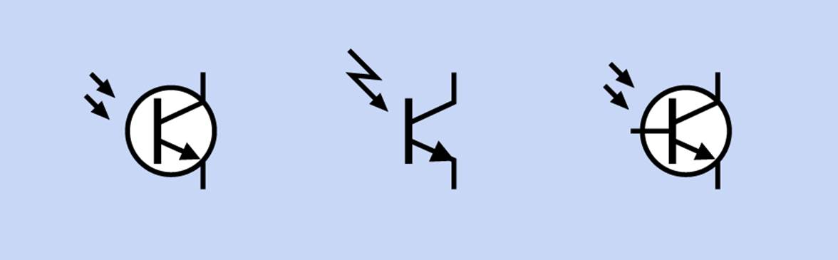
Figure 3-1. Schematic symbols representing a phototransistor. Those at left and center are functionally identical. The symbol on the right indicates that a connection to the base is available to supplement the voltage induced by incoming light.
Don’t confuse phototransistors with photoresistors! Photoresistors are commonly known as photocells, and I referred to them in Make: Electronics. They are convenient to use, because they don’t require a separate power supply. They simply vary their resistance in response to light. Because they usually contain cadmium sulfide, which is regarded as hazardous to the environment, they are not widely stocked at large retailers such as http://www.mouser.com. You can still find them on eBay, but I avoid specifying them in a circuit because they may be difficult to obtain in the future.
Phototransistors are now widely used as a substitute, with applications ranging from switching streetlights on and off to sensing an infrared signal when you press a button on your TV remote.
Photosensitive Audio Pitch
§ Remember that you will find components for each experiment listed at the back of the book. See Appendix B.
Begin by assembling the circuit shown in Figure 3-2. I’m using a 555 timer because it’s always useful for doing a demo. The output from the original bipolar version of the 555 can drive an LED, or a relay—or a small loudspeaker, as in this example. The more modern CMOS version, which often has a part number with 7555 in it, cannot deliver so much output power.
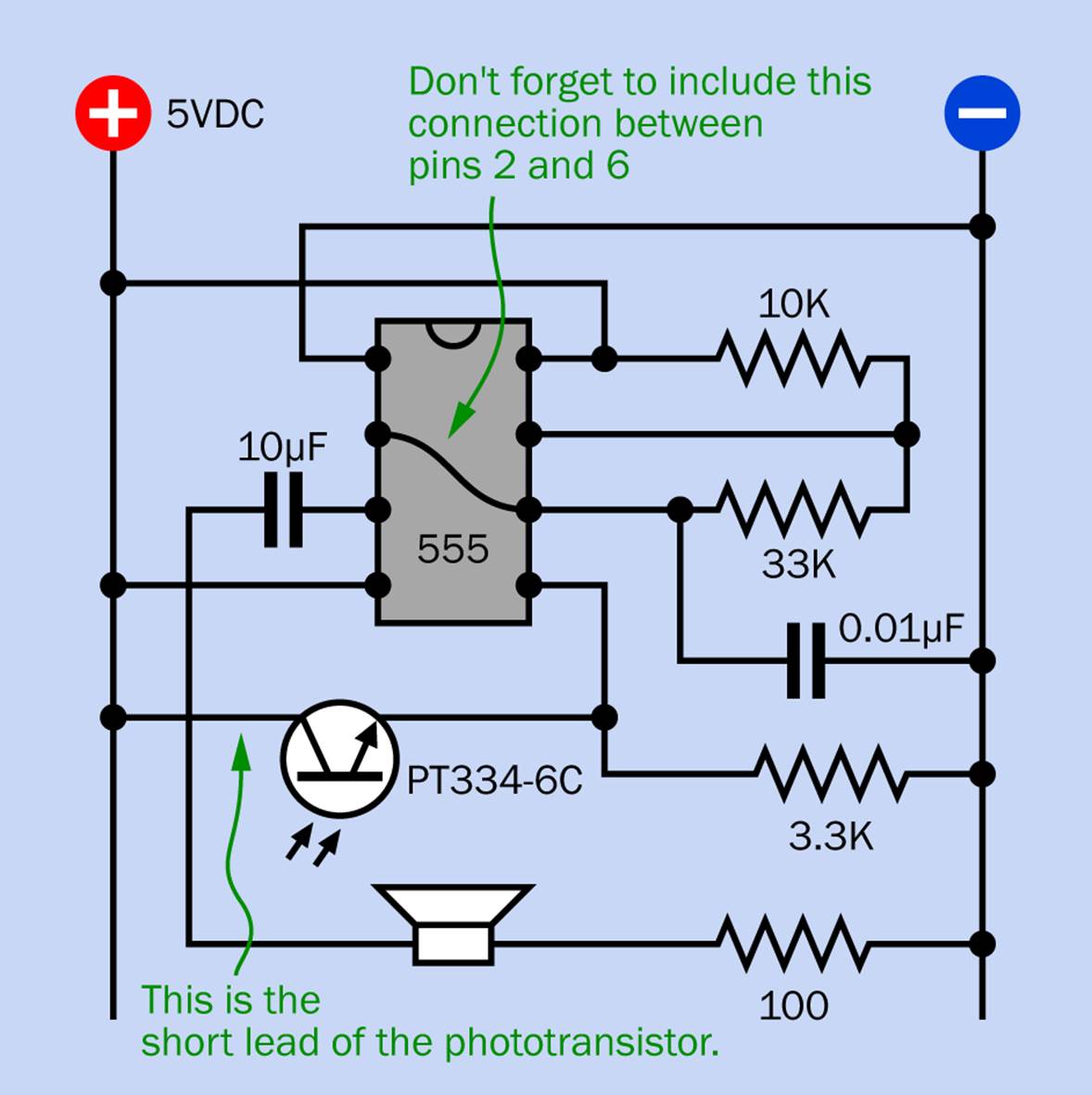
Figure 3-2. This demo circuit creates an audible indication of the function of a phototransistor.
You have to be careful to install the phototransistor the right way around. Here’s the rule:
§ Positive current enters a phototransistor through the short lead, and exits through the long lead.
Therefore, the short lead should be at the left in this schematic.
This is confusing, because LEDs look identical to phototransistors, and you know that the long lead of an LED always has to be “more positive” than the short one. Phototransistors are the other way around. You can think of a phototransistor as being opposite to an LED, because it absorbs light instead of emitting light. Consequently, its connection is opposite.
Here’s another rule. Because LEDs and phototransistors can look virtually identical:
§ Make sure you store your phototransistors in a container that is carefully labelled, so you don’t get them mixed up with your LEDs!
A photograph of this circuit is shown in Figure 3-3. In this photograph, the 100Ω resistor in series with the loudspeaker is omitted, because I used a loudspeaker with 63Ω impedance. All the other connections in the circuit are the same.
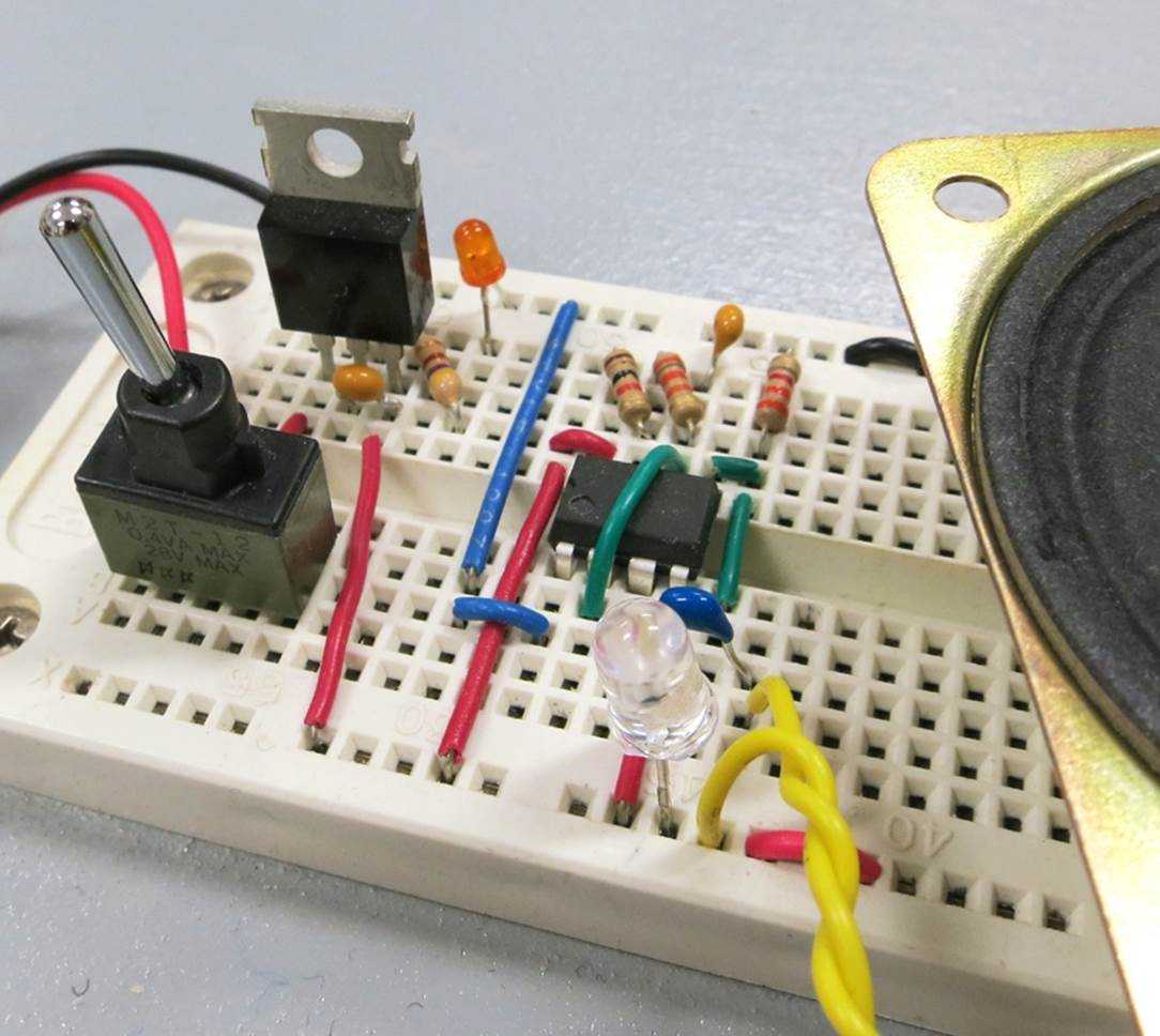
Figure 3-3. A breadboarded version of the phototransistor test circuit using a 555 timer. The phototransistor is the transparent object at the center near the yellow wires. A loudspeaker is partially visible on the right.
Remember to include the jumper wire connecting pin 2 of the 555 timer with pin 6. This jumper is a green wire in the photograph, and is shown crossing the chip in the schematic. When you feel sure that the connections are correct, power it up to discover how the sounds from the loudspeaker will change as you vary the light on the phototransistor.
The pinouts of the 555 timer are shown in Figure 3-4. I’ll remind you of their functions in more detail in the next experiment.
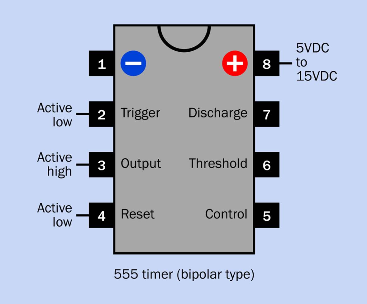
Figure 3-4. Pin functions of the 555 timer. The supply voltage range applies only to the original TTL, bipolar type of the chip.
Experiment by substituting different values for the 10K and 33K resistors. Or try a slightly larger or smaller value for the 0.01µF capacitor. Do you recall the formula for determining the frequency of a free-running timer? I’ll remind you of the basic info in the next experiment. The key fact here is that pin 5 (the pin at the bottom-right corner of the chip) is the control pin. The voltage applied to this pin adjusts the reference value that the timer users, when it decides that each “on” cycle is complete, and flips into its “off” cycle. Consequently, the control pin adjusts the pitch of the sound that the timer creates when it is running at an audio frequency.
The combination of the phototransistor and the 3.3K resistor works as a voltage divider, in the same way that I described on What About the Voltage?. When light shines on the phototransistor, its effective internal resistance drops, changing the voltage to pin 5 on the timer. But how do we know how much the voltage drops? Let’s find out.
All materials on the site are licensed Creative Commons Attribution-Sharealike 3.0 Unported CC BY-SA 3.0 & GNU Free Documentation License (GFDL)
If you are the copyright holder of any material contained on our site and intend to remove it, please contact our site administrator for approval.
© 2016-2026 All site design rights belong to S.Y.A.