Make: More Electronics (2014)
Chapter 4. Experiment 4: Measuring Light
§ Remember that you will find components for each experiment listed at the back of the book. See Appendix B.
Check the very simple schematic in Figure 4-1, which looks quite similar to the circuit in Figure 2-8. You can add it as a separate circuit to your breadboard, without dismantling the circuit that you built in Experiment 3. Just move the phototransistor and the resistor farther down your breadboard.
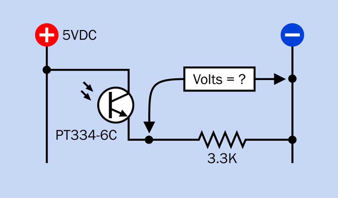
Figure 4-1. A test circuit for a phototransistor.
The resistor that I have chosen is 3.3K, because I want to get the widest possible range of voltages from the phototransistor emitter, and I found that 3.3K does the job.
Now, shine some light on the phototransistor, and measure the voltage at the emitter. Try using a desk lamp, a white LED, a flashlight, or a colored LED. The incoming light creates a very small current in the base of the phototransistor, which amplifies a larger current flowing from the collector through to the emitter.
§ A brighter light lowers the effective internal resistance. You can remember this by thinking of the light driving the resistance away.
If you remember what I wrote about a voltage divider at the end of Experiment 2, you’ll see that when the phototransistor has a low effective internal resistance, the voltage that you measure in the circuit shown in Figure 4-1 will increase. The phototransistor provides less of a barrier between the measuring point and the source of positive current. In this particular circuit:
§ Bright light increases the voltage at the emitter.
This only holds true if you wire the components as in Figure 4-1.
Now swap them around as in Figure 4-2. The voltage will go down in brighter light, because the phototransistor is now providing less resistance between your measuring point and negative ground.
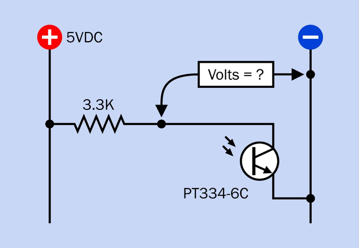
Figure 4-2. If the phototransistor and the resistor trade places, the voltage at the point between them will be reduced in brighter light.
Using Phototransistors
Phototransistors are available in many variants. The one I chose is sensitive to a wide range of light frequencies, so you can shine just about any color of light at it and get a response. Many phototransistors are only sensitive to infrared frequencies, because they’re intended for activation by infrared-emitting LEDs. When the phototransistor and the LED have the same narrow band of sensitivity, there’s less chance of picking up noise or erroneous signals.
Bear in mind that your meter has a high resistance. If you remove it and substitute a component with a relatively low resistance, it will compete with the 3.3K resistor to suck current out of the phototransistor, possibly overloading it. Fortunately for our purposes, logic chips, microcontrollers, and other digital devices have a high input impedance, so we can attach them directly to the phototransistor emitter—so long as we use an appropriate power supply, which will usually be 5VDC.
If you drive the input of a digital chip with the output from an analog device (such as a transistor or phototransistor), you should always be careful to measure the actual voltage going into the chip under all conditions that may exist in the future, to make sure that the voltage stays in an acceptable range. See Figure B-4.
Quick Facts About Phototransistors
§ Phototransistors are classified according to the wavelengths of light to which they are sensitive, measured in nanometers, abbreviated nm.
§ The human eye can perceive light ranging from around 380nm to 750nm.
§ Infrared has a wavelength longer than 750nm. Ultraviolet has a wavelength shorter than 380nm. Phototransistors exist that are sensitive only to ultraviolet, but they are uncommon.
§ Infrared phototransistors are usually solid black in appearance.
Background: Photons and Electrons
Light is a source of energy, and the phototransistor uses that energy to induce a flow of electrons. Several types of light-conversion components exist:
§ Photodiodes contain a semiconductor that can be penetrated by photons (“particles” of light). The photons dislodge some electrons that cross a boundary into an adjacent n-type semiconductor layer, building an electrical potential. The response is quite linear, making a photodiode suitable for use in a light meter.
§ Solar cells are photodiodes that have a very large surface area.
§ Phototransistors work on the same general principle as a photodiode, except that an external DC power source helps to energize the electron flow, which is now controlled by light instead of being created by light.
§ A photodarlington is a phototransistor that functions as a two-stage amplifier, like a darlington transistor. It has greater light sensitivity than a regular phototransistor, but a slower response time.
§ Photoresistors, also often referred to as “photocells,” lower their resistance in response to light.
Quick Facts About the 555
Make: Electronics contained a very thorough section on the 555 timer. I’m just going to refresh your memory by summarizing a few details that are important:
Pin functions
It’s useful to be able to grab a 555 without a lot of thought whenever you want a single pulse or a train of pulses to test a component. Turn back to Figure 3-4 for a reminder of the names of the pins on the timer.
Monostable circuit
Figure 4-3 may help to remind you of the basic behavior of a timer in monostable mode, also known as one-shot mode. A transition to low voltage on the trigger pin creates a high pulse from the output pin. The duration of the pulse is determined by the value of resistor R1 and capacitor C1, as the resistor charges the capacitor. If the reset pin of the timer will not be used, it is tied to the positive side of the power supply to prevent it from being activated unintentionally.
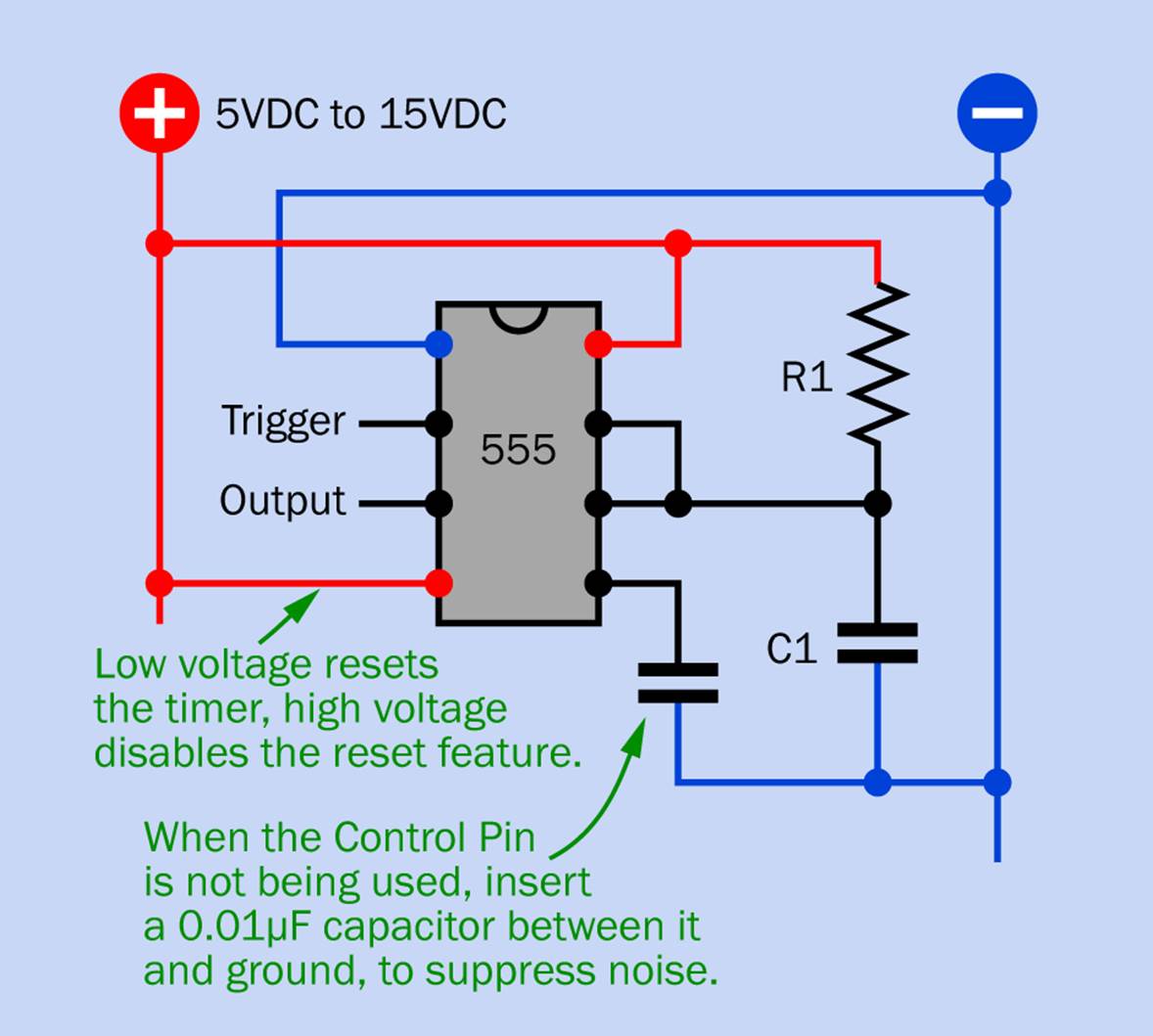
Figure 4-3. A simplified schematic showing typical connections of a 555 timer in monostable mode.
Monostable pulse duration
Figure 4-4 is a quick-reference table of pulse durations, in seconds, for various values of resistor R1 and capacitor C1, when the timer is in monostable mode. You’ll find a more detailed table in Make: Electronics or manufacturers’ datasheets.
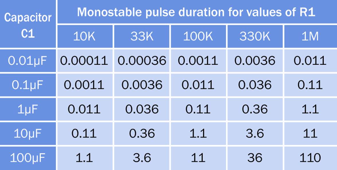
Figure 4-4. Pulse duration, in seconds, of a 555 timer running in monostable mode.
Astable circuit
Figure 4-5 reminds you of the basic wiring to make the timer function in astable or free-running mode, creating a stream of pulses. In this configuration, the timer starts itself and continues running so long as (a) power is applied to it and (b) voltage on the reset pin is not allowed to go low.
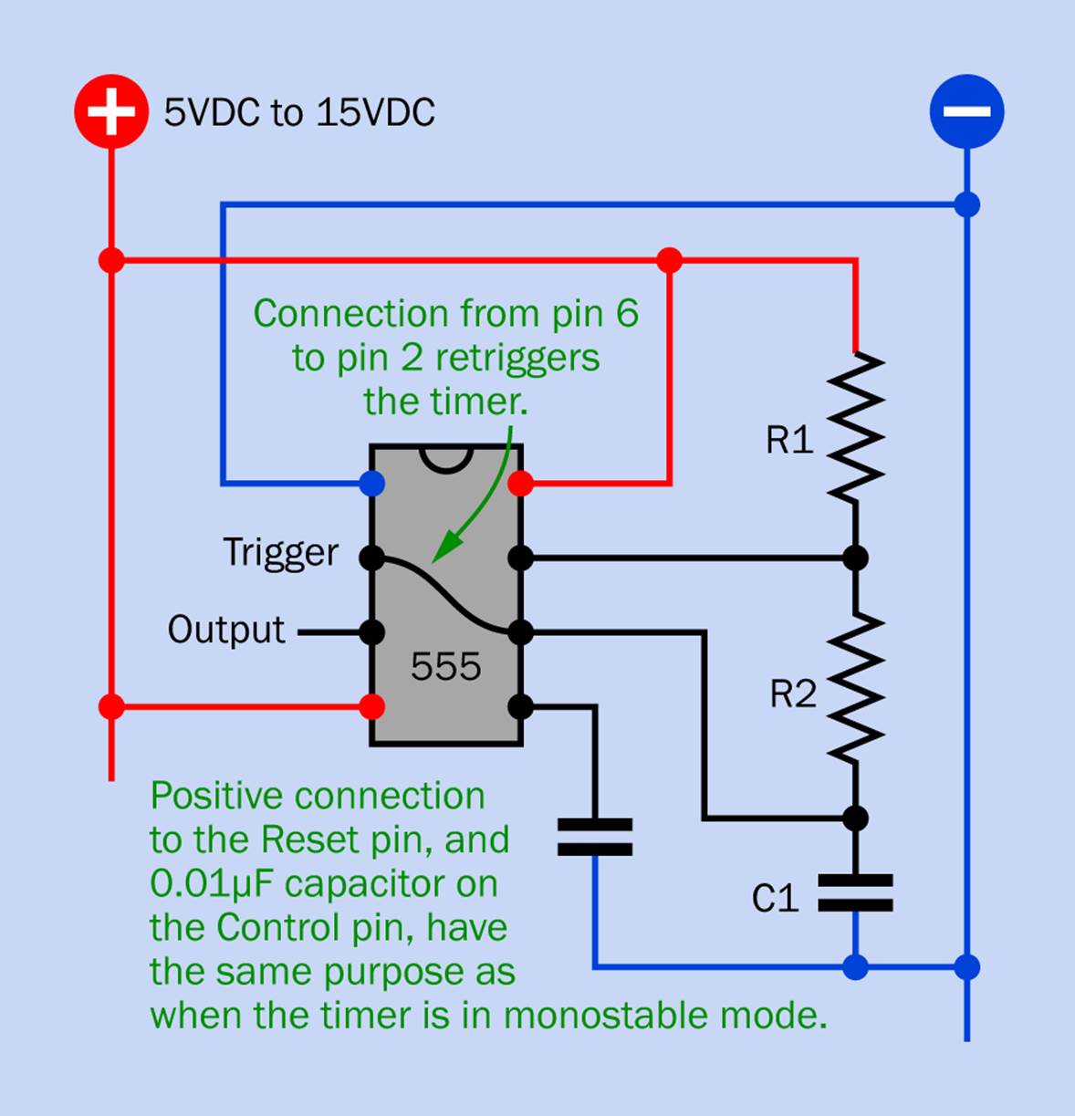
Figure 4-5. A simplified schematic showing the 555 timer functionality in astable mode.
Basic astable principle
Figure 4-6 shows the basic principle of operation in astable mode, as the capacitor charges through R1 and R2 and then discharges through R2 into the chip. This explains why the “on” output duration is always longer than the “off” output duration.
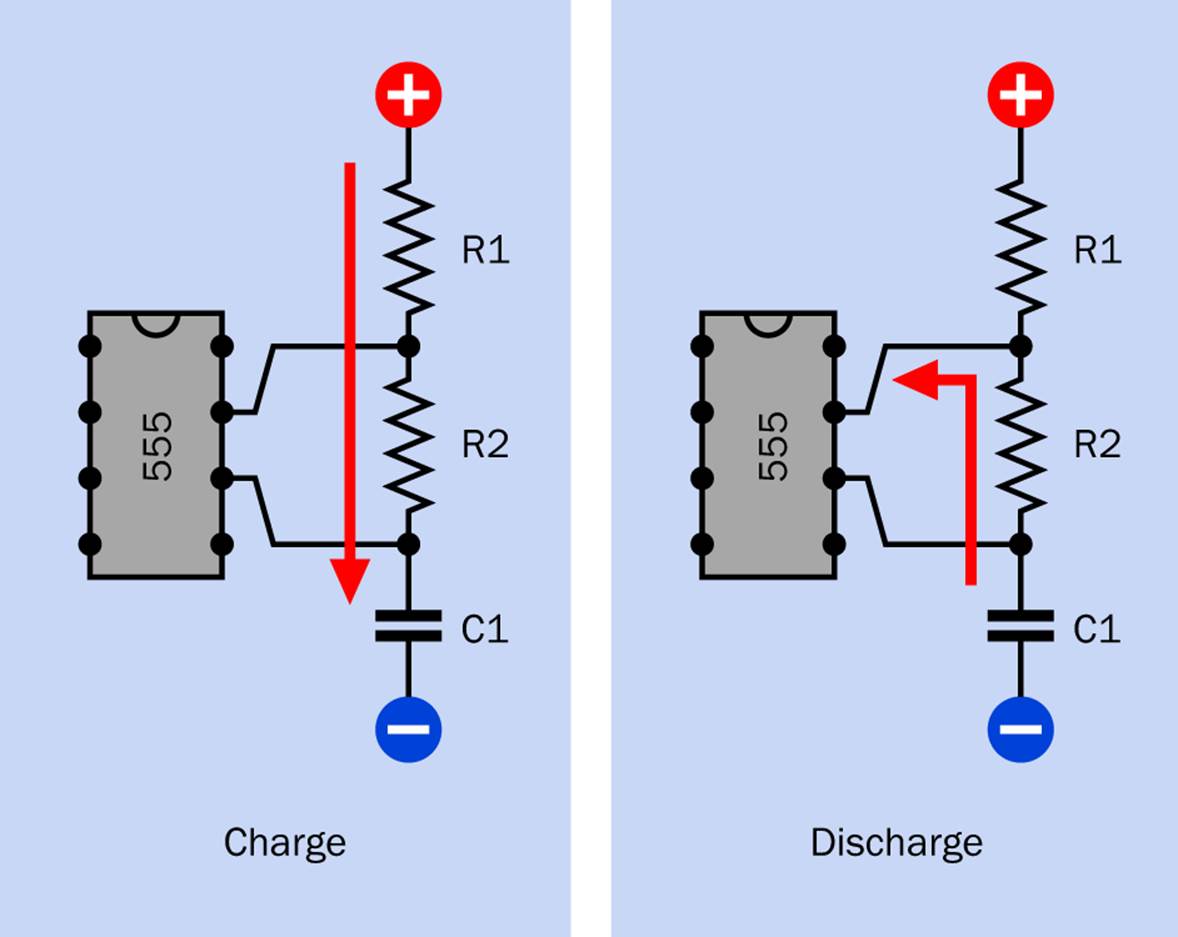
Figure 4-6. The principle of operation of a timer in astable mode, charging capacitor C1 through R1 + R2 and discharging through R2.
Astable frequency
Figure 4-7 is a quick-reference table of output frequencies, in Hz, for various values of C1 and R2, assuming 10K as a value for R1, when the timer runs in astable mode. (You can use lower values for R1, but the chip will consume more power.)
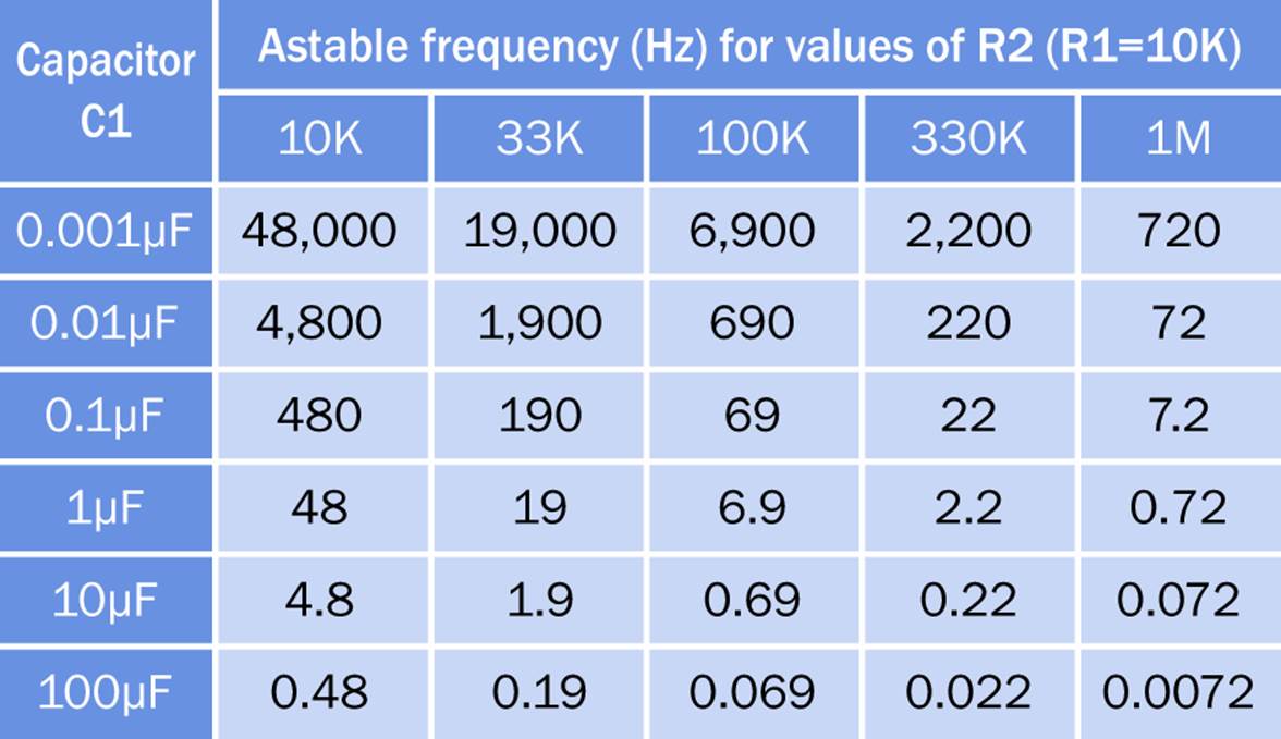
Figure 4-7. The output frequencies for a 555 timer running in astable mode with a fixed value of 10K for R1 and various values for R2 and C1.
Total cycle time
The total cycle time of a timer in astable mode is proportional to R1 + R2 + R2, because a full cycle consists of one “on” pulse plus the gap between it and the next pulse. This is shown graphically in Figure 4-8.
Frequency calculation
If you measure R1 and R2 in kilohms, while C1 is measured in microfarads, you can calculate the frequency, F, in Hertz, of a 555 timer running in astable mode, using this formula, where R is R1 + R2 + R2:
F = 1440 / (R * C1)
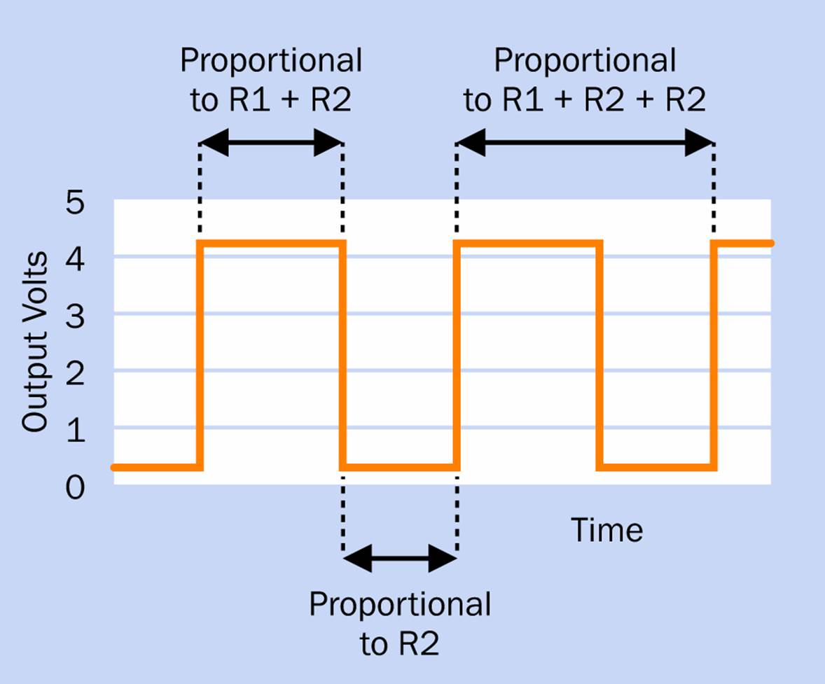
Figure 4-8. A graphical representation of “on” and “off” durations in a 555 timer (using a 5VDC power supply) running in astable mode, showing why the total time from the beginning of one cycle to the beginning of the next is proportionate to R1 + R2 + R2.
Large capacitors
Very high capacitor values (above, say, 470µF) are likely to produce unreliable results, because of leakage. This is the undesirable feature of capacitors (especially electrolytics) whereby imperfections allow some loss of charge. Leakage from a big capacitor can become comparable to the current flowing into it, if you’re trying to charge it through a high resistance.
Speed measurement
If you want to know how fast your timer is running, and the speed is faster than you can log with a stopwatch, and you don’t have an oscilloscope, you can substitute a capacitor of 10 times or 100 times the correct value, and the timer duration should increase proportionately. Because capacitors are manufactured within very wide tolerances, and because of the leakage issue mentioned above, substitution will only give you an approximate result.
Power source
The power supply for a 555 can be as low as 5VDC and as high as 15VDC without affecting the pulse rate significantly.
Output voltage
The 555 high output voltage is slightly lower than its power supply voltage. If you want the output to drive a logic chip that is fussy about high and low voltage inputs, check the voltage output of the 555 while it is running extremely slowly (e.g., a five-second pulse) to give your meter time to respond. A 10K pullup resistor or pulldown resistor may be used on the input to the logic chip.
If any of these reminders is unclear to you, please go back to Make: Electronics, or another introductory book, or a manufacturer’s datasheet, for clarification.
Quick Facts About CMOS Versus Bipolar
The original type of 555 timer (still being manufactured) contains bipolar transistors. It is often referred to as a TTL chip, and has these characteristics:
§ Not very vulnerable to static electricity
§ Accepts a wide range of power-supply voltages
§ Sources or sinks up to 200mA
§ Creates spikes of noise when it switches on and off
§ Uses a relatively large amount of power
The more modern CMOS version has different characteristics:
§ Is more vulnerable to static electricity
§ Requires a narrower range of voltage
§ Cannot source or sink much current (the amount varies, depending on the manufacturer)
§ Does not create voltage spikes caused by switching
§ Uses very little power
Confusingly, the CMOS and bipolar versions may both be referred to as “555 timers,” and their part numbers can be very similar. From Texas Instruments, for instance, the TLC555-Q1 is a CMOS version, while the NE555P is bipolar. Even more confusing, some CMOS versions are 3.3-volt devices, while some require 5VDC, and others will accept a wider voltage range.
If you go shopping on your own, read the datasheets carefully. A CMOS timer will not drive the loudspeaker in this experiment.
All materials on the site are licensed Creative Commons Attribution-Sharealike 3.0 Unported CC BY-SA 3.0 & GNU Free Documentation License (GFDL)
If you are the copyright holder of any material contained on our site and intend to remove it, please contact our site administrator for approval.
© 2016-2026 All site design rights belong to S.Y.A.