Make: More Electronics (2014)
Chapter 5. Experiment 5: That Whooping Sound
Instead of using a phototransistor to adjust the voltage on the control pin of the 555 timer, you can use the output from a second timer running at a much slower speed. This automates the up-and-down shifts in sound frequency.
In Figure 5-1 the previous schematic has been extended downward. (A photograph of a breadboarded version appears in Figure 5-2.) The output from a second timer is connected up to the control pin of the first timer, through a 47µF coupling capacitor. Why is the coupling capacitor there? To create a “whooping” sound. What do I mean by that? Well, you’ll recognize it when you hear it.
The second timer uses a 150K resistor to charge your choice of a 1µF or 10µF timing capacitor. Try the 10µF capacitor first. This will cause the timer to run at about one cycle per second. Initially it has has no effect on the first timer, but the output from the second timer slowly charges the 47µF coupling capacitor, causing the pitch of the first timer to rise up gradually. Then the lower timer reaches the end of its “on” cycle and flips into its “off” cycle. At this point, the coupling capacitor discharges, and the frequency of the upper timer drops back down.
I included a circuit of this type in Experiment 17 in Make: Electronics, but the sound it produced was different. You can compare that schematic with the following one, and see if you can figure out why.
In Figure 5-1, if you substitute a 1µF timing capacitor for the 10µF timing capacitor, everything happens ten times as fast, and you get the distinctive noise that is typical of burglar alarms. (That’s what I meant by a whooping sound.) You can have fun trying different values for the timing resistors and capacitors, and varying the coupling capacitor, to achieve the most absolutely annoying, aggravating noise possible.
The phototransistor adds to the possibilities. Experiment by varying the light that falls on it, and see what happens if you wave your fingers over the phototransistor to vary the light very quickly.
What could you achieve by using two phototransistors to adjust the voltages on the control pins of both timers?
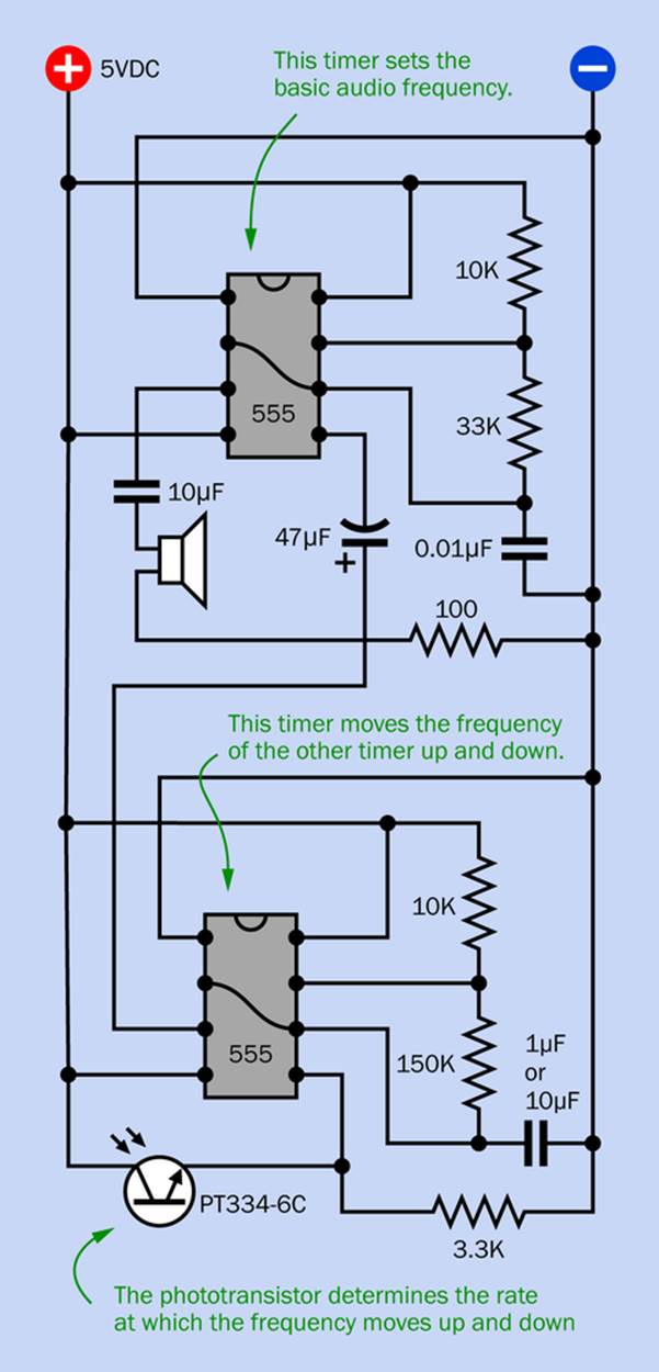
Figure 5-1. By using a second 555 timer to adjust the voltage on the control pin of the first timer, you can achieve a really annoying “whooping” sound.
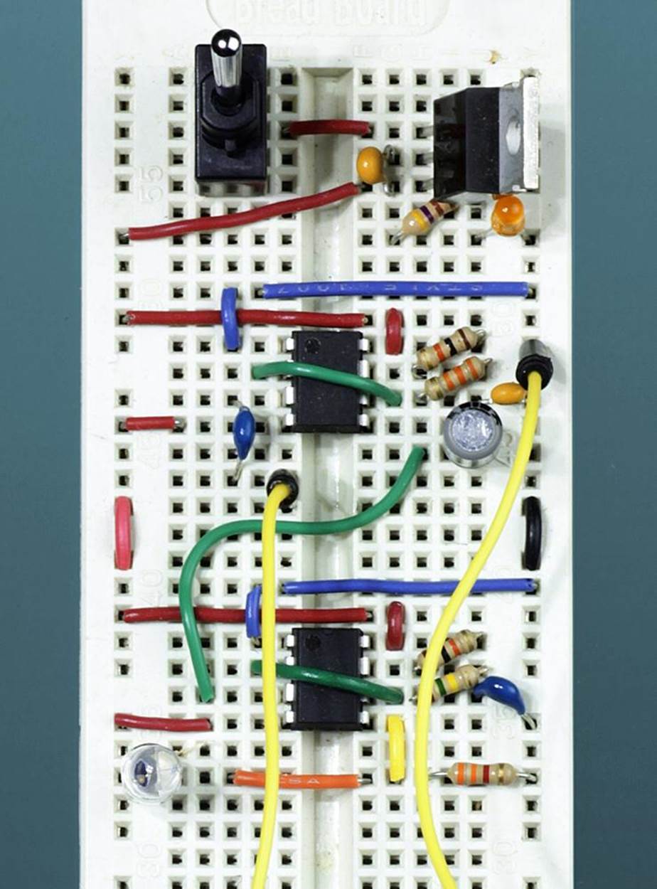
Figure 5-2. A breadboarded version of the two-timer schematic.
Make Even More
We have many alternatives to the 555 timer that were designed to circumvent the limitations that I listed at the end of the previous experiment:
§ The 7555 is pin-compatible but uses less current, can be run from a voltage as low as 2VDC, and creates less noise in a circuit. The maximum supply voltage and maximum source current vary, depending on the manufacturer.
§ The 4047B provides additional features that make it more versatile. One trigger pin responds to a positive-to-negative transition; another responds to a negative-to-positive transition. It also has two complementary outputs, one of which is high when the other is low. The timer runs as a one-shot or in astable multivibrator mode, depending on the setting of another pin. The power supply range is equivalent to that of the old bipolar 555.
§ The 74HC221 is a dual monostable timer chip. In other words, it contains two timers, each of which runs in one-shot mode. When they are wired to trigger each other, the result is a pulse stream where you can set the high duration and low duration independently of each other. The maximum supply voltage is 7VDC, but this is really intended to be used as a 5VDC device.
§ The 4528B is a dual monostable timer using a concept that is similar to the 74HC221, but as an old-style CMOS device, it tolerates a wider range of power supply voltage (up to 15VDC).
§ Other dual monostable timers include the 74HC123, 74HC423, 74HC4538, and 4098B, all adopting the same general principle but with slightly differing specifications.
§ The 556 is a dual timer consisting of two 555s in one chip. They can be used to trigger each other, but have the usual limitations of a classic 555. The 556 chip is not as popular as it used to be, and may eventually become unobtainable. For this reason, and because it is often more convenient to place a single timer exactly where you want it on a circuit board, 556 chips are not used in this book.
§ Lastly there is the 74HC5555, which contains a 24-stage counter. This divides the clock frequency by values up to about 16 million, allowing the timed interval to extend for days if you wish. An external crystal oscillator can be used for greater accuracy than a resistor-capacitor combination, but the typical high speed of a crystal oscillator will reduce the maximum pulse duration of the timer—unless you use two or more in a chain, with each triggering the next.
With so many options, all of which boast features lacking in a 555 timer, why is the old bipolar 555 still so popular? Probably because everyone is familiar with it. Like a QWERTY keyboard, it’s not ideal, but we all know how to use it. Also, the old original bipolar through-hole version can source more current than any of its successors. This is handy for quick-and-simple circuits.
And it’s cheap!
You might consider trying some of the variants listed above. Personally I never get tired of playing with timers, because these simple chips create so many possibilities. But it’s time to move on, because we have a new component to deal with: the comparator.
All materials on the site are licensed Creative Commons Attribution-Sharealike 3.0 Unported CC BY-SA 3.0 & GNU Free Documentation License (GFDL)
If you are the copyright holder of any material contained on our site and intend to remove it, please contact our site administrator for approval.
© 2016-2026 All site design rights belong to S.Y.A.