PIC32 Microcontrollers and the Digilent chipKIT: Introductory to Advanced Projects (2015)
Chapter 1. Microcomputer Systems
Abstract
This chapter is an introduction to microcontrollers. The basic features of microcontrollers are described briefly with some typical application areas of microcontrollers.
Keywords
Microcontrollers
Microprocessors
Microcontroller features
Microcontroller applications
1.1. Introduction
The term microcomputer is used to describe a system that includes a minimum of a microprocessor, program memory, data memory, and input–output (I/O). Some microcomputer systems include additional components such as timers, counters, analogue-to-digital converters (ADCs), and so on. Thus, a microcomputer system can be anything from a large computer having hard disks, floppy disks, and printers to a single-chip embedded controller.
In this book, we are going to consider only the type of microcomputers that consists of a single silicon chip. Such microcomputer systems are also called microcontrollers, and they are used in many household goods such as microwave ovens, TV remote control units, cookers, hi-fi equipment, CD players, personal computers, fridges, etc. There are a large number of microcontrollers available in the market. In this book, we shall be looking at the programming and system design using the 32-bit programmable interface controller (PIC) series of microcontrollers manufactured by Microchip Technology Inc.
1.2. Microcontroller Systems
A microcontroller is a single-chip computer. Micro suggests that the device is small, and controller suggests that the device can be used in control applications. Another term used for microcontrollers is embedded controller, since most of the microcontrollers are built into (or embedded in) the devices they control.
A microprocessor differs from a microcontroller in many ways. The main difference is that a microprocessor requires several other components for its operation, such as program memory and data memory, I/O devices, and external clock circuit. A microcontroller, on the other hand, has all the support chips incorporated inside the same chip. All microcontrollers operate on a set of instructions (or the user program) stored in their memory. A microcontroller fetches the instructions from its program memory one by one, decodes these instructions, and then carries out the required operations.
Microcontrollers have traditionally been programmed using the assembly language of the target device. Although the assembly language is fast, it has several disadvantages. An assembly program consists of mnemonics, and it is difficult to learn and maintain a program written using the assembly language. Also, microcontrollers manufactured by different firms have different assembly languages and the user is required to learn a new language every time a new microcontroller is to be used. Microcontrollers can also be programmed using a high-level language, such as BASIC, PASCAL, and C. High-level languages have the advantage that it is much easier to learn a high-level language than an assembler. Also, very large and complex programs can easily be developed using a high-level language.
In general, a single chip is all that is required to have a running microcontroller system. In practical applications, additional components may be required to allow a microcomputer to interface to its environment. With the advent of the PIC family of microcontrollers, the development time of an electronic project has reduced to several hours.
Basically, a microcomputer (or microcontroller) executes a user program that is loaded in its program memory. Under the control of this program, data is received from external devices (inputs), manipulated, and then sent to external devices (outputs). For example, in a microcontroller-based fluid level control system, the fluid level is read by the microcomputer via a level sensor device and the microcontroller attempts to control the fluid level at the required value. If the fluid level is low, the microcomputer operates a pump to draw more fluid from the reservoir in order to keep the fluid at the required level. Figure 1.1 shows the block diagram of our simple fluid level control system.
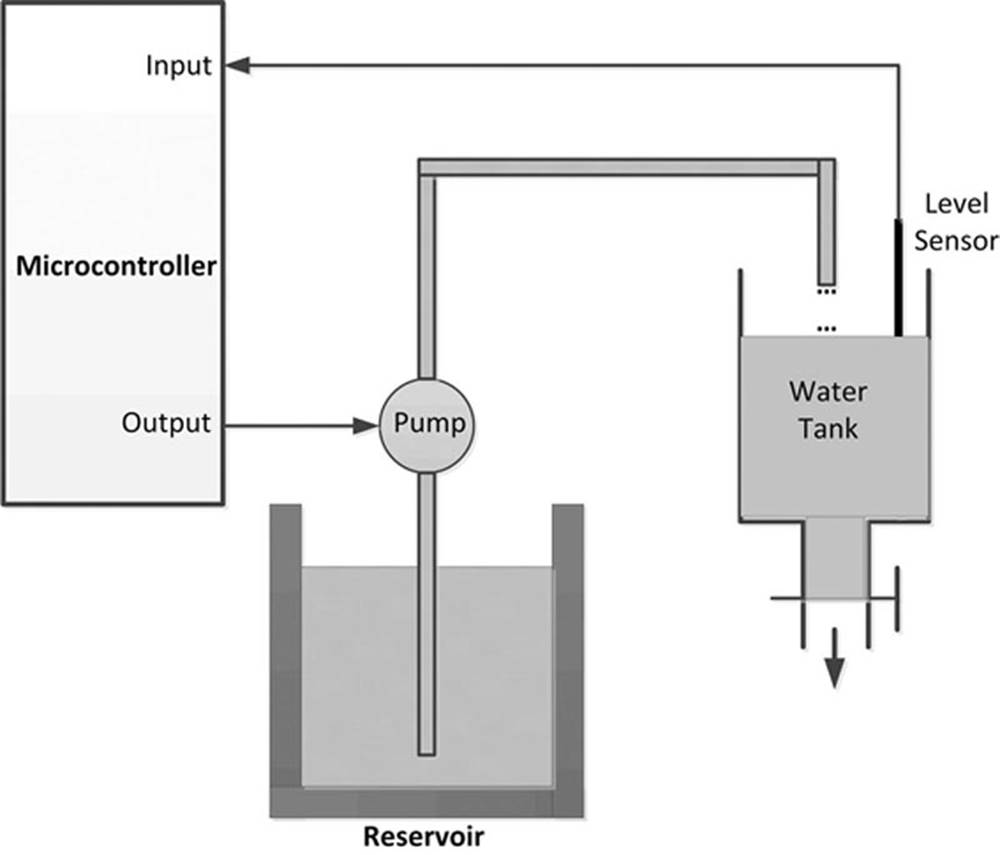
FIGURE 1.1 Microcontroller-Based Fluid Level Control System
The system shown in Figure 1.1 is a very simplified fluid level control system. In a more sophisticated system, we may have a keypad to set the required fluid level and an LCD to display the current level in the tank. Figure 1.2 shows the block diagram of this more sophisticated fluid level control system.
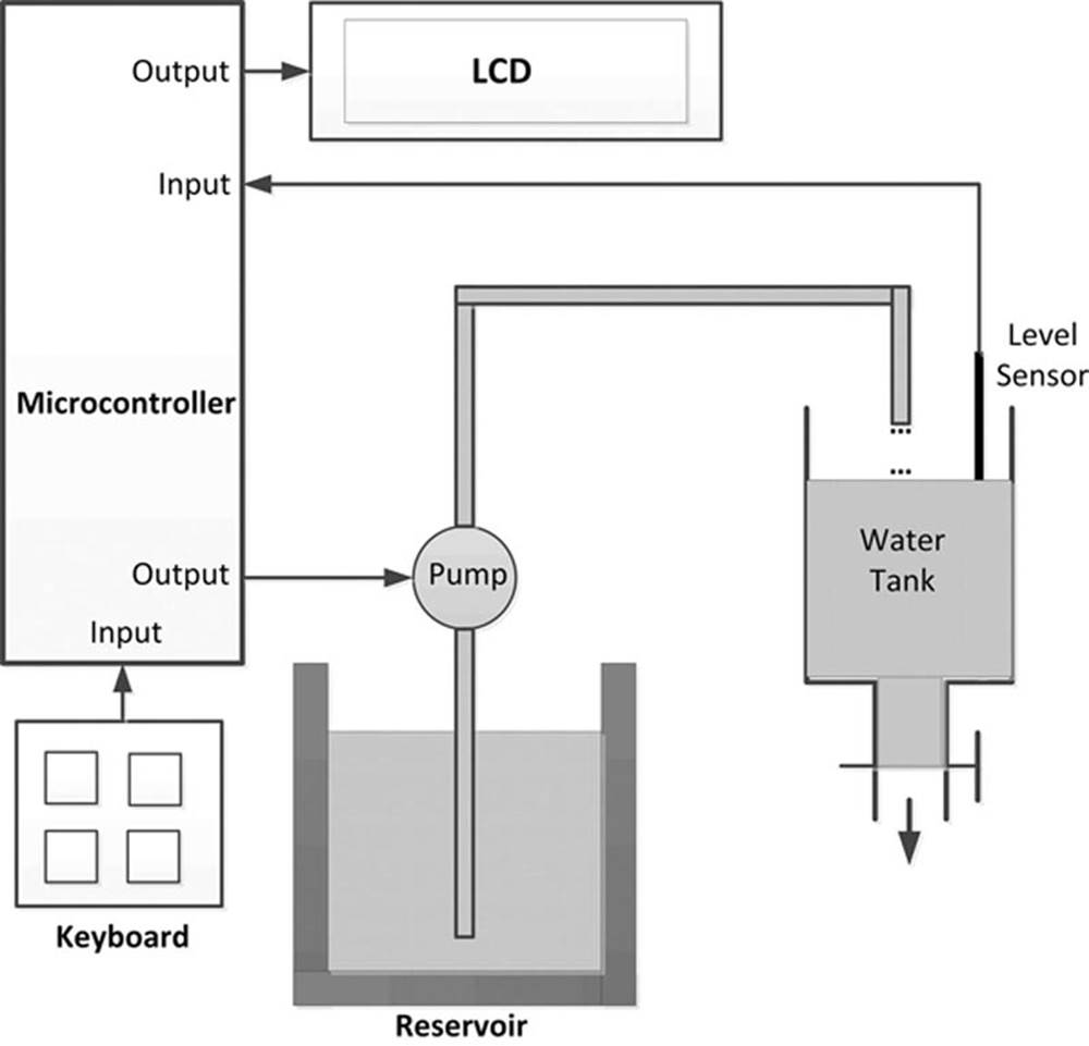
FIGURE 1.2 Fluid Level Control System With a Keypad and LCD
We can make our design even more sophisticated (see Figure 1.3) by adding an audible alarm to inform us if the fluid level is outside the required value. Also, the actual level at any time can be sent to a PC every second for archiving and further processing. For example, a graph of the daily fluid level changes can be plotted on the PC. As you can see, because the microcontrollers are programmable, it is very easy to make the final system as simple or as complicated as we like.
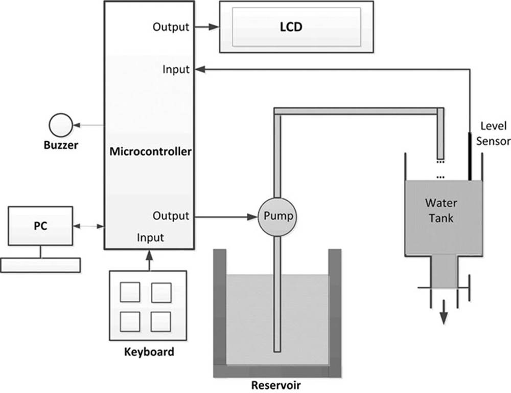
FIGURE 1.3 More Sophisticated Fluid Level Controller
A microcontroller is a very powerful tool that allows a designer to create sophisticated I/O data manipulation under program control. Microcontrollers are classified by the number of bits they process. 8-bit devices are the most popular ones and are used in most low-cost, low-speed microcontroller-based applications. 16- and 32-bit microcontrollers are much more powerful, but usually more expensive, and their use may not be justified in many small- to medium-sized general-purpose applications.
The simplest microcontroller architecture consists of a microprocessor, memory, and I/O. The microprocessor consists of a central processing unit (CPU) and the control unit (CU). The CPU is the brain of the microcontroller, and this is where all of the arithmetic and logic operations are performed. The CU controls the internal operations of the microprocessor and sends out control signals to other parts of the microcontroller to carry out the required instructions.
Memory is an important part of a microcontroller system. Depending on the type used, we can classify memories into two groups: program memory and data memory. Program memory stores the programs written by the programmer, and this memory is usually nonvolatile, that is, data is not lost after the removal of power. Data memory is where the temporary data used in a program is stored, and this memory is usually volatile, that is, data is lost after the removal of power.
There are basically six types of memories, summarised as follows.
1.2.1. RAM
RAM means random access memory. It is a general-purpose memory that usually stores the user data in a program. RAM memory is volatile in the sense that it cannot retain data in the absence of power, that is, data is lost after the removal of power. Most microcontrollers have some amount of internal RAM. Several kilobytes is a common amount, although some microcontrollers have much more, and some have less. For example, the PIC32MX460F512L 32-bit microcontroller has 512 kilobytes of RAM. In general, it is possible to extend the memory by adding external memory chips.
1.2.2. ROM
ROM is read-only memory. This type of memory usually holds program or fixed user data. ROM is nonvolatile. If power is removed from ROM and then reapplied, the original data will still be there. ROM memories are programmed at factory during the manufacturing process, and their contents cannot be changed by the user. They are useful only if we have developed a program and wish to order several thousand copies of it, or if we wish to store some configuration data.
1.2.3. PROM
PROM is programmable read-only memory. This is a type of ROM that can be programmed in the field, often by the end user, using a device called a PROM programmer. Once a PROM has been programmed, its contents cannot be changed. PROMs are usually used in low-production applications where only several such memories are required.
1.2.4. EPROM
EPROM is erasable programmable read-only memory. This is similar to ROM, but the EPROM can be programmed using a suitable programming device. EPROM memories have a small clear glass window on top of the chip where the data can be erased under strong ultraviolet light. Once the memory is programmed, the window can be covered with dark tape to prevent accidental erasure of the data. An EPROM memory must be erased before it can be reprogrammed. Many development versions of microcontrollers are manufactured with EPROM memories where the user program can be stored. These memories are erased and reprogrammed until the user is satisfied with the program. Some versions of EPROMs, known as one-time programmable (OTP), can be programmed using a suitable programmer device, but these memories cannot be erased. OTP memories cost much less than the EPROMs. OTP is useful after a project has been developed completely and it is required to make many copies of the program memory.
1.2.5. EEPROM
EEPROM is electrically erasable programmable read-only memory, which is a nonvolatile memory. These memories can be erased and also be reprogrammed using suitable programming devices. EEPROMs are used to save configuration information, maximum and minimum values, identification data, etc.
1.2.6. Flash EEPROM
This is another version of EEPROM-type memory. This memory has become popular in microcontroller applications and is generally used to store the user program. Flash EEPROM is nonvolatile and is usually very fast. The data can be erased and then reprogrammed using a suitable programming device. These memories can also be programmed without removing them from their circuits. Some microcontrollers have only 1k flash EEPROM, while some others have 32k or more.
1.3. Microcontroller Features
Microcontrollers from different manufacturers have different architectures and different capabilities. Some may suit a particular application, while others may be totally unsuitable for the same application. The hardware features of microcontrollers in general are described in this section.
1.3.1. Supply Voltage
Most microcontrollers operate with the standard logic voltage of +5 V. Some microcontrollers can operate at as low as +2.7 V, and some will tolerate +6 V without any problems. You should check the manufacturers’ data sheets about the allowed limits of the power supply voltage. For example, PIC32MX460F512L 32-bit microcontrollers can operate with a power supply of +2.3 to +3.6 V.
A voltage regulator circuit is usually used to obtain the required power supply voltage when the device is to be operated from a mains adaptor or batteries. For example, a 5 V regulator may be required if the microcontroller and peripheral devices operate from a +5 or +3.3 V supply and a 9 V battery is to be used as the power supply.
1.3.2. The Clock
All microcontrollers require a clock (or an oscillator) to operate. The clock is usually provided by connecting external timing devices to the microcontroller. Most microcontrollers will generate clock signals when a crystal and two small capacitors are connected. Some will operate with resonators or external resistor–capacitor pairs. Some microcontrollers have built-in timing circuits, and they do not require any external timing components. If your application is not time-sensitive, you should use external or internal (if available) resistor–capacitor timing components for simplicity and low cost.
An instruction is executed by fetching it from the memory and then decoding it. This usually takes several clock cycles and is known as the instruction cycle. PIC32 series of microcontrollers can operate with clock frequencies up to 80 MHz.
1.3.3. Timers
Timers are important parts of any microcontroller. A timer is basically a counter that is driven either from an external clock pulse or from the internal oscillator of the microcontroller. A PIC32 microcontroller can have 16- or 32-bit wide timers (two 16-bit timers are combined to create a 32-bit timer). Data can be loaded into a timer under program control, and the timer can be stopped or started by program control. Most timers can be configured to generate an interrupt when they reach a certain count (usually when they overflow). The interrupt can be used by the user program to carry out accurate timing-related operations inside the microcontroller.
Some microcontrollers offer capture and compare facilities where a timer value can be read when an external event occurs, or the timer value can be compared with a preset value and an interrupt can be generated when this value is reached. PIC32 microcontrollers can have up to five capture inputs.
1.3.4. Watchdog
Most microcontrollers have at least one watchdog facility. The watchdog is basically a timer that is refreshed by the user program and a reset occurs if the program fails to refresh the watchdog. The watchdog timer is used to detect a system problem, such as the program being in an endless loop. A watchdog is a safety feature that prevents runaway software and stops the microcontroller from executing meaningless and unwanted code. Watchdog facilities are commonly used in real-time systems for safety where it may be required to regularly check the successful termination of one or more activities.
1.3.5. Reset Input
A reset input is used to reset a microcontroller externally. Resetting puts the microcontroller into a known state such that the program execution starts from a known address. An external reset action is usually achieved by connecting a push-button switch to the reset input such that the microcontroller can be reset when the switch is pressed.
1.3.6. Interrupts
Interrupts are very important concepts in microcontrollers. An interrupt causes the microcontroller to respond to external and internal (e.g., a timer) events very quickly. When an interrupt occurs, the microcontroller leaves its normal flow of program execution and jumps to a special part of the program, known as the interrupt service routine (ISR). The program code inside the ISR is executed, and on return from the ISR the program resumes its normal flow of execution.
The ISR starts from a fixed address of the program memory. This address is also known as the interrupt vector address. Some microcontrollers with multi-interrupt features have just one interrupt vector address, while some others have unique interrupt vector addresses, one for each interrupt source. Interrupts can be nested such that a new interrupt can suspend the execution of another interrupt. Another important feature of a microcontroller with multi-interrupt capability is that different interrupt sources can be given different levels of priority.
1.3.7. Brown-Out Detector
Brown-out detectors are also common in many microcontrollers, and they reset a microcontroller if the supply voltage falls below a nominal value. They are safety features, and they can be employed to prevent unpredictable operation at low voltages, especially to protect the contents of EEPROM-type memories.
1.3.8. Analogue-to-Digital Converter
An ADC is used to convert an analogue signal such as voltage to a digital form so that it can be read and processed by a microcontroller. Some microcontrollers have built-in ADC converters. It is also possible to connect an external ADC converter to any type of microcontroller. PIC32 microcontroller ADC converters are usually 10-bit wide, having 1024 quantisation levels. Most PIC microcontrollers with ADC features have multiplexed ADC converters where more than one analogue input channel is provided. For example, PIC32MX460F512L microcontroller has 16 channels of ADC converters, each 10-bit wide.
The ADC conversion process must be started by the user program, and it may take several tens of microseconds for a conversion to complete. ADC converters usually generate interrupts when a conversion is complete so that the user program can read the converted data quickly and efficiently.
ADC converters are very useful in control and monitoring applications since most sensors (e.g., temperature sensor, pressure sensor, force sensor) produce analogue output voltages.
1.3.9. Serial Input–Output
Serial communication (also called RS232 communication) enables a microcontroller to be connected to another microcontroller or to a PC using a serial cable. Some microcontrollers have built-in hardware called universal synchronous–asynchronous receiver–Transmitter (UART) to implement a serial communication interface. The baud rate (bits per second) and the data format can usually be selected by the user program. If any serial I/O hardware is not provided, it is easy to develop software to implement serial data communication using any I/O pin of a microcontroller. PIC32MX460F512L microcontroller provides two UART modules, each with RS232-, RS485-, LIN-, or IrDA-compatible interfaces.
In addition, two Serial Peripheral Interface (SPI) and two Integrated InterConnect (I2C) hardware bus interfaces are available on the PIC32MX460F512L microcontroller.
1.3.10. EEPROM Data Memory
EEPROM-type data memory is also very common in many microcontrollers. The advantage of an EEPROM memory is that the programmer can store nonvolatile data in such a memory, and can also change this data whenever required. For example, in a temperature monitoring application, the maximum and the minimum temperature readings can be stored in an EEPROM memory. Then, if the power supply is removed for whatever reason, the values of the latest readings will still be available in the EEPROM memory.
1.3.11. LCD Drivers
LCD drivers enable a microcontroller to be connected to an external LCD display directly. These drivers are not common since most of the functions provided by them can easily be implemented in software.
1.3.12. Analogue Comparator
Analogue comparators are used where it is required to compare two analogue voltages. These modules are not available in low-end PIC microcontrollers. PIC32MX460F512L microcontrollers have two built-in analogue comparators.
1.3.13. Real-Time Clock
Real-time clock enables a microcontroller to have absolute date and time information continuously. Built-in real-time clocks are not common in most microcontrollers since they can easily be implemented by either using an external dedicated real-time clock chip or writing a program. For example, PIC32MX460F512L microcontroller has built-in real-time clock and calendar module.
1.3.14. Sleep Mode
Some microcontrollers offer built-in sleep modes where executing this instruction puts the microcontroller into a mode where the internal oscillator is stopped and the power consumption is reduced to an extremely low level. The main reason of using the sleep mode is to conserve the battery power when the microcontroller is not doing anything useful. The microcontroller usually wakes up from the sleep mode by external reset or by a watchdog time-out.
1.3.15. Power-On Reset
Some microcontrollers have built-in power-on reset circuits that keep the microcontroller in reset state until all the internal circuitry has been initialised. This feature is very useful as it starts the microcontroller from a known state on power-up. An external reset can also be provided where the microcontroller can be reset when an external button is pressed.
1.3.16. Low-Power Operation
Low-power operation is especially important in portable applications where the microcontroller-based equipment is operated from batteries, and very long battery life is a main requirement. Some microcontrollers can operate with less than 2 mA with 5 V supply, and around 15 μA at 3 V supply.
1.3.17. Current Sink/Source Capability
This is important if the microcontroller is to be connected to an external device that may draw large current for its operation. PIC32 microcontrollers can source and sink 18 mA of current from each output port pin. This current is usually sufficient to drive LEDs, small lamps, buzzers, small relays, etc. The current capability can be increased by connecting external transistor switching circuits or relays to the output port pins.
1.3.18. USB Interface
USB is currently a very popular computer interface specification used to connect various peripheral devices to computers and microcontrollers. PIC32 microcontrollers normally provide built-in USB modules.
1.3.19. Motor Control Interface
Some PIC microcontrollers, for example, PIC18F2x31, provide motor control interface.
1.3.20. CAN Interface
CAN bus is a very popular bus system used mainly in automation applications. Some PIC18F series of microcontrollers (e.g., PIC18F4680) provide CAN interface capabilities.
1.3.21. Ethernet Interface
Some PIC microcontrollers (e.g., PIC18F97J60) provide Ethernet interface capabilities. Such microcontrollers can easily be used in network-based applications.
1.3.22. ZigBee Interface
ZigBee is an interface similar to Bluetooth and is used in low-cost wireless home automation applications. Some PIC series of microcontrollers provide ZigBee interface capabilities, making the design of such wireless systems very easy.
1.3.23. Multiply and Divide Hardware
PIC32 microcontrollers have built-in hardware for fast multiplication and division operations.
1.3.24. Operating Temperature
It is important to know the operating temperature range of a microcontroller chip before a project is developed. PIC32 microcontrollers can operate in the temperature range −40 to +105°C.
1.3.25. Pulse Width Modulated (PWM) Outputs
Most microcontrollers provide PWM outputs for driving analogue devices such as motors, lamps, etc. The PWM is usually a separate module and runs in hardware, independent of the CPU.
1.3.26. JTAG Interface
Some high-end microcontrollers (e.g., PIC32MX460F512L) have built-in JTAG interfaces for enhanced debugging interface.
1.3.27. Package Size
It is sometimes important to know the package size of a microcontroller chip before a microcontroller is chosen for a particular project. Low-end microcontrollers are usually packaged in 18-, 28-, or 40-pin DIL packages. High-end microcontrollers, for example, PIC32MX460F512L, are housed in a 100-pin TQFP-type package.
1.3.28. DMA
Some high-end microcontrollers have built-in direct memory access (DMA) channels that can be used to transfer large amounts of data between different devices without the intervention of the CPU. For example, PIC32MX460F512L microcontroller has four DMA channels.
1.4. Microcontroller Architectures
Usually two types of architectures are used in microcontrollers (see Figure 1.4): Von Neumann architecture and Harvard architecture. Von Neumann architecture is used by a large percentage of microcontrollers, and here all memory space is on the same bus and instruction and data use the same bus. In the Harvard architecture (used by most PIC microcontrollers), code and data are on separate buses, and this allows the code and data to be fetched simultaneously, resulting in an improved performance.
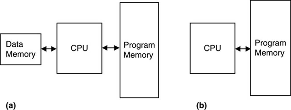
FIGURE 1.4 (a) Harvard and (b) Von Neumann Architectures
1.4.1. RISC and CISC
Reduced instruction set computer (RISC) and complex instruction set computer (CISC) refer to the instruction set of a microcontroller. In an 8-bit RISC microcontroller, data is 8-bit wide but the instruction words are more than 8-bit wide (usually 12-, 14-, or 16-bit) and the instructions occupy one word in the program memory. Thus, the instructions are fetched and executed in one cycle, resulting in an improved performance.
In a CISC microcontroller, both data and instructions are 8-bit wide. CISC microcontrollers usually have over 200 instructions. Data and code are on the same bus and cannot be fetched simultaneously.
1.5. 8, 16, or 32 Bits?
People are usually confused for making a decision between 8, 16, or 32 bits of microcontrollers. It is important to realise that the number of bits just refers to the width of the data handled by the processor. This number actually limits the precision of mathematical operations carried out by the CPU (although it is possible to emulate higher-order mathematics in software or by using special hardware).
In general, 8-bit microcontrollers have been around since the first days of the microcontroller development. They are cheap, easy to use (only small package size), low speed, and can be used in most general-purpose control and data manipulation operations. For example, it is still very efficient to design low- to medium-speed control systems (e.g., temperature control, fluid level control, or robotics applications) using 8-bit microcontrollers. In such applications, low cost is more important than high speed. Many commercial and industrial applications fall into this category and can easily be designed using standard 8-bit microcontrollers.
16- and 32-bit microcontrollers, on the other hand, usually cost more, but they offer much higher speeds, and much higher precision in mathematical operations. These microcontrollers are usually housed in larger packages (e.g., 64 or 100 pins) and offer much more features, such as larger data and program memories, more timer/counter modules, more and faster A/D channels, more I/O ports, and so on. 32-bit microcontrollers are usually used in high-speed, real-time digital signal processing applications where also high precision is a requirement, such as digital image processing, digital audio processing, and so on. Most consumer products, such as electronic games and mobile phones, are based on 32-bit processors as they demand high-speed real-time operation with colour graphical displays and with touchscreen panels. Other high-speed applications such as video capturing, image filtering, video editing, video streaming, speech recognition, and speech processing all require very fast 32-bit processors with lots of data and program memories, and very high precision while implementing the digital signal processing algorithms.
This book is about 32-bit PIC microcontrollers. We shall be seeing the basic architectures and features of these microcontrollers. In addition, many working projects will be given in the book to illustrate how these microcontrollers can be programmed and used in real applications. The Cerebot MX3cK Development Board (has been renamed to chipKIT MX3) will be used in the projects.
1.6. Summary
This chapter has given an introduction to the microprocessor and microcontroller systems. The basic building blocks of microcontrollers have been described briefly with reference to various types of memories used in microcontroller systems.
1.7. Exercises
1. What is a microcontroller? What is a microprocessor? Explain the main differences between a microprocessor and a microcontroller.
2. Give some examples of applications of microcontrollers around you.
3. Where would you use an EPROM memory?
4. Where would you use a RAM memory?
5. Explain what types of memories are usually used in microcontrollers.
6. What is an input–output port?
7. What is an analogue-to-digital converter? Give an example use for this converter.
8. Explain why a watchdog timer could be useful in a real-time system.
9. What is serial input–output? Where would you use serial communication?
10. Why is the current sinking/sourcing important in the specification of an output port pin?
11. What is an interrupt? Explain what happens when an interrupt is recognised by a microcontroller.
12. Why is brown-out detection important in real-time systems?
13. Explain the differences between a RISC-based microcontroller and a CISC-based microcontroller. What type of microcontroller is PIC?
All materials on the site are licensed Creative Commons Attribution-Sharealike 3.0 Unported CC BY-SA 3.0 & GNU Free Documentation License (GFDL)
If you are the copyright holder of any material contained on our site and intend to remove it, please contact our site administrator for approval.
© 2016-2026 All site design rights belong to S.Y.A.