PIC32 Microcontrollers and the Digilent chipKIT: Introductory to Advanced Projects (2015)
Chapter 3. PIC32 Microcontroller Development Tools
Abstract
This chapter describes the various development tools available in the marketplace for the development of projects using 32-bit microcontrollers. It also describes the basic operation of simulators, in-circuit debuggers, assemblers, and compilers. The advantages and disadvantages of simulators and in-circuit debuggers are given in this chapter. In addition, examples are given on how to use a simulator and an in-circuit debugger. The features of various development hardware, such as development boards, and development kits are described with reference to the manufacturers. Examples are given to show how some of these development boards can be used in real applications.
Keywords
Microcontroller development tools
Simulators
In-circuit debuggers
Assemblers
Compilers
Breadboards
Development boards
Development kits
The development of a microcontroller-based system is a complex process. Development tools are hardware and software tools that help programmers to develop and test systems in a relatively short time.
Developing software and hardware for microcontroller-based systems involves the use of editors, assemblers, compilers, debuggers, simulators, emulators, and device programmers. A typical development cycle starts with writing the application program using a text editor. The program is then translated into the executable code by using an assembler or a compiler. If the program consists of several modules, these are combined together into a single application program using a linker. At this stage, any syntax errors are detected by the assembler or the compiler and they have to be corrected before an executable code can be generated. In the next stage of the development cycle, a simulator can be used to test the application program without the actual hardware. Simulators can be useful to test the correctness of an algorithm or a program with limited or no input–outputs. Most of the errors can be removed during the simulation. When the program seems to be working, the next stage of the development cycle is to load the executable code to the target microcontroller chip using a device programmer and then test the overall system logic. During this cycle, software and hardware tools such as in-circuit debuggers or in-circuit emulators can be used to analyse the operation of the program, and to display the variables and registers in real time by setting breakpoints in the program.
Development tools for microcontrollers can be classified into two categories: software and hardware. There are many such tools, and the discussion of all these tools is beyond the scope of this book. In this chapter, the commonly used tools are reviewed briefly.
3.1. Software Development Tools
Software development tools are basically computer programs, and they usually run on personal computers, helping the programmer (or system developer) to create and/or modify or test applications programs. Some of the commonly used software development tools are the following:
• Text editors
• Assemblers/compilers
• Simulators
3.1.1. Text Editors
A text editor is a program that allows us to create or edit programs and text files. Windows operating system is distributed with a text editor program called Notepad. Using the Notepad, we can create a new program file, modify an existing file, or display or print the contents of a file. It is important to realise that programs used for word processing, such as the Word, cannot be used as a text editor. This is because word processing programs are not true text editors as they embed word formatting characters such as bold, italic, underline, etc., inside the text.
Most assemblers and compilers have built-in text editors. Using these editors, we can create our program and then assemble or compile it without having to exit from the editor environment. These editors also provide additional features, such as automatic keyword highlighting, syntax checking, parenthesis matching, comment line identification, and so on. Different parts of a program can be shown in different colours to make the program more readable. For example, comments can be shown in one colour, keywords in another colour, conditional statements in a different colour, and so on. These features can speed up the program development process since most syntax errors can be eliminated during the programming stage.
3.1.2. Assemblers and Compilers
Assemblers generate executable code from assembly language programs. The generated code is usually loaded into the flash program memory of the target microcontroller.
Similarly, compilers generate executable code from high-level language programs. Some of the commonly used compilers for the PIC32 microcontrollers are BASIC, C, PASCAL, MPIDE, and C++.
Assembly language is used in applications where the processing speed is very critical and the microcontroller is required to respond to external and internal events in the shortest possible time. The main disadvantage of assembly language is that it is difficult to develop complex programs using this language. Also, assembly language programs cannot be maintained easily. High-level languages, on the contrary, are easier to learn and complex programs can be developed and tested in a much shorter time. The maintenance of high-level programs is also much easier than the maintenance of assembly language programs.
3.1.3. Simulators
A simulator is a computer program that runs on a PC without any microcontroller hardware, and it simulates the behaviour of the target microcontroller by interpreting the user program instructions using the target microcontroller instruction set. Simulators can display the contents of registers, memory, and the status of input–output ports of the target microcontroller as the user program is interpreted. The user can set breakpoints to stop execution of the program at desired locations and then examine the contents of various registers at the breakpoint. In addition, the user program can be executed in a single-step mode and the memory and registers can be examined as the program executes a single instruction each time a key is pressed. One problem associated with standard simulators is that they are only software tools and any hardware interface is not simulated.
Most microcontroller language development tools also incorporate some form of simulators.
3.1.4. High-Level Language Simulators
These are also known as source-level debuggers, and, like simulators, they are programs that run on a PC. A source-level debugger allows us to find the errors in our high-level programs. We can set breakpoints in high-level statements, execute the program up to the breakpoint, and then display the values of program variables, the contents of registers, and memory locations at the breakpoint. For example, we can stop a program execution and examine (or modify) the contents of an array.
A source-level debugger can also invoke hardware-based debugging activity using a hardware debugger device. For example, the user program on the target microcontroller can be stopped and the values of various variables and registers can be examined.
3.1.5. Simulators With Hardware Simulation
Some simulators (e.g., Labcenter Electronics VSM, http://www.labcenter.com) incorporate hardware simulation options where various software simulated hardware devices can be connected to microcontroller I/O pins. For example, an electromagnetic motor software module can be connected to an I/O port and its operation can be simulated in software. Although the hardware simulation does not simulate the actual device exactly, it is very useful during early project development cycle.
3.1.6. Integrated Development Environment (IDE)
IDEs are powerful PC-based programs that include everything to edit, assemble, compile, link, simulate, source-level debug, and download the generated executable code to the physical microcontroller chip (using a programmer device). These programs are in the form of graphical user interface (GUI) where the user can select various options from the program without having to exit the program. IDEs can be extremely useful during the development phases of microcontroller-based systems. Most PIC32 high-level language compilers are in the form of an IDE, thus enabling the programmer to do most tasks within a single software development tool.
3.2. Hardware Development Tools
There are numerous hardware development tools available for the PIC32 microcontrollers. Some of these products are manufactured by Microchip Inc., and some by third-party companies. The popular hardware development tools are the following:
• Development boards
• Device programmers
• In-circuit debuggers
• In-circuit emulators
• Breadboards
3.2.1. Development Boards
The development boards are invaluable microcontroller development tools. Simple development boards contain just a microcontroller and the necessary clock circuitry. Some sophisticated development boards contain LEDs, LCDs, push-buttons, serial ports, USB ports, power supply circuits, device programming hardware, etc.
In this section, we shall be looking at the specifications of some of the commercially available PIC32 microcontroller development boards.
PIC32 Starter Kit
This board (see Figure 3.1) is manufactured by Microchip Inc. and can be used in PIC32 microcontroller-based project development. The kit includes everything to write, compile, program, debug, and execute a program.
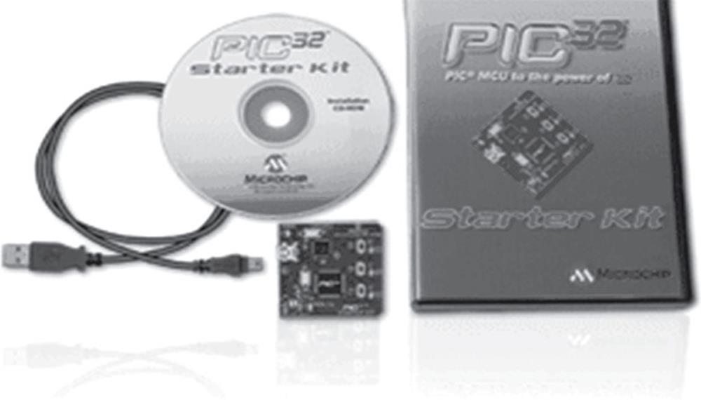
FIGURE 3.1 PIC32 Starter Kit
The kit contains the PIC32 Starter Kit board and a USB Mini-B cable.
The board contains the following:
• PIC32MX360F512L 32-bit microcontroller
• Regulated power supply (+3.3 V) for powering via the USB port
• Processor running at 72 MHz
• On-board debugging
• Debug and power on LEDs
• Three push-button switches for user inputs
• Three LED indicators
• Connectors for I/O ports
• Interface to the I/O expansion board
A total of 35 example programs are provided with the kit. Users can download a free MPLAB C32 compiler with limited functionality from company’s web site and use the compiler in their projects.
The I/O expansion board (see Figure 3.2) provides full access to all the microcontroller I/O signals. Additional daughter boards can be attached to the expansion board for added functionality.
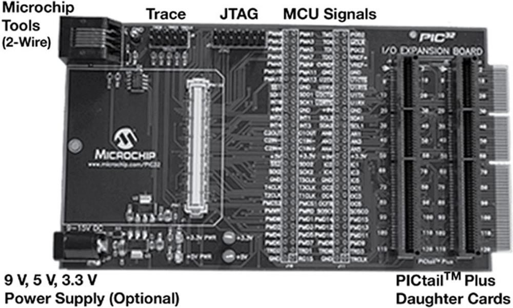
FIGURE 3.2 I/O Expansion Board
Microstick II
Microstick II from Microchip Inc. is a small (the size of a stick of gum), low-cost development board (see Figure 3.3), designed for small applications with a few I/O port requirements. The kit is supplied with the following:
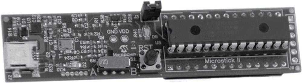
FIGURE 3.3 Microstick II
• Microstick II board
• USB cable
• PIC32MX250F128 microcontroller (in addition, PIC24 and dsPIC33 microcontrollers are also included)
• Integrated USB programmer/debugger
• LED and reset button
• Pin headers for I/O access
The board is distributed with free demo programs.
PIC32 USB Starter Kit II
The PIC32 USB Starter Kit II (see Figure 3.4) is a low-cost PIC32 microcontroller development board with USB and CAN functionality. Users can develop USB- and CAN-based applications easily using this kit.
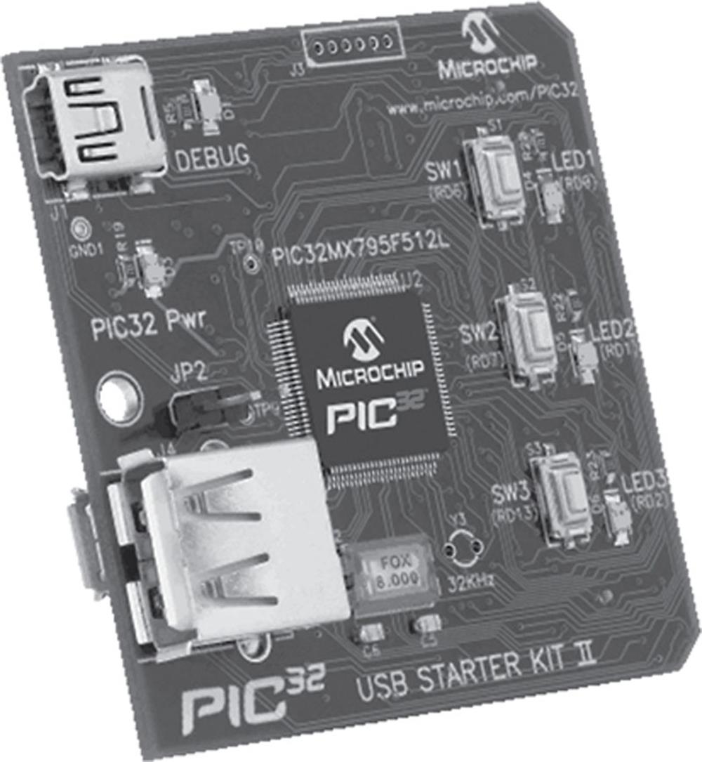
FIGURE 3.4 PIC32 USB Starter Kit II
The kit has the following features:
• PIC32MX795F512L 32-bit microcontroller
• On-board crystal
• USB for on-board programming/debugging
• Three push-button switches for user inputs
• Three LED indicators
• Debug and power LEDs
• Regulated power supply
• I/O connector for various expansion boards
PIC32 Ethernet Starter Kit
The PIC32 Ethernet Starter Kit (see Figure 3.5) is a low-cost 10/100 Ethernet development kit manufactured by Microchip Inc., using the PIC32 microcontroller.
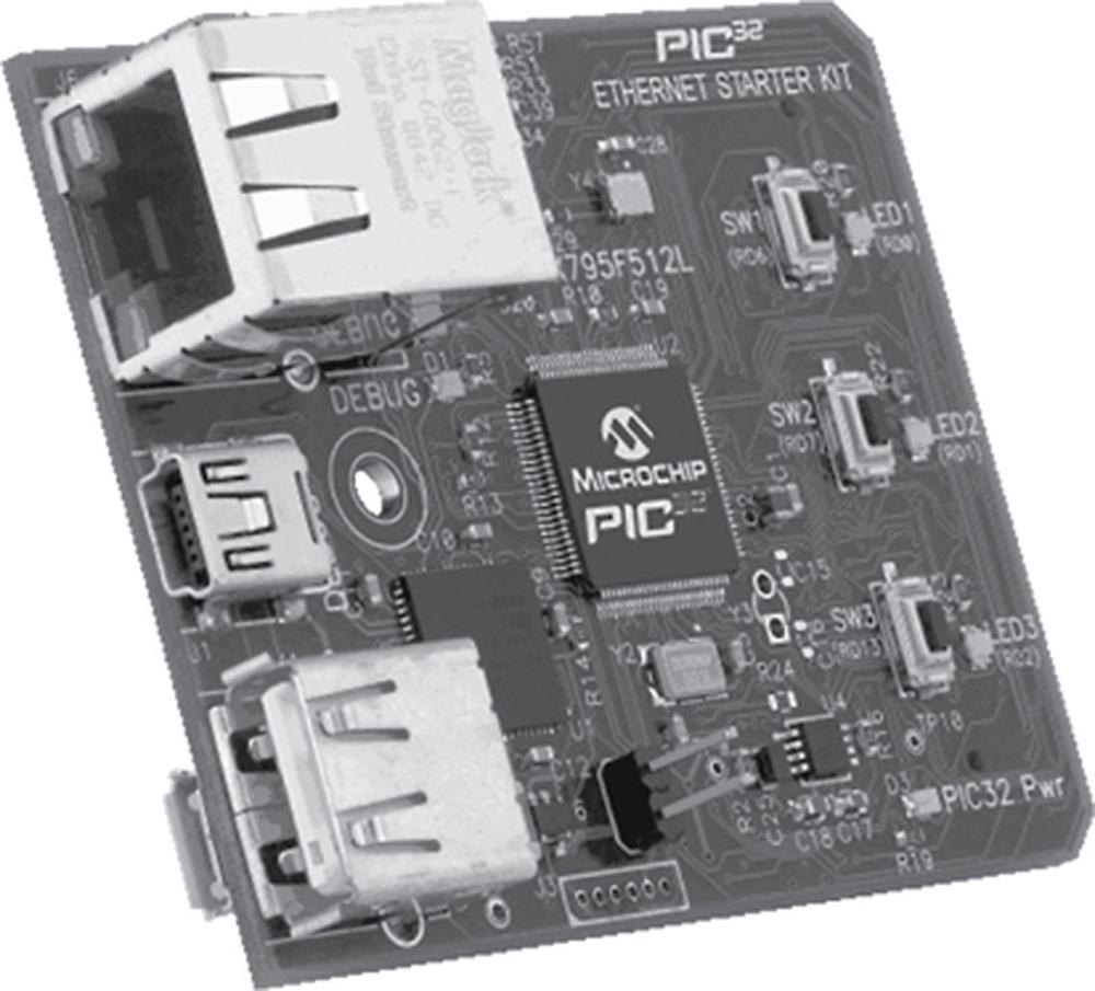
FIGURE 3.5 PIC32 Ethernet Starter Kit
The board has the following features:
• PIC32MX795F512L 32-bit microcontroller
• 32-Bit microcontroller for on-board programming/debugging
• On-board crystal
• Ethernet oscillator
• Three push-button switches for user input
• Three LED indicators
• Debug and power supply LEDs
• RJ-45 Ethernet port
• Connector for various expansion boards
Cerebot MX3cK
The Cerebot MX3cK (see Figure 3.6) is a 32-bit microcontroller development board based on PIC32MX320F128H, and is manufactured by Digilent (www.digilentinc.com). The kit is of low cost and contains everything needed to start developing embedded applications based on 32-bit PIC microcontrollers using the MPIDE IDE. In order to use MPLAB IDE, a programming/debugging device is required.
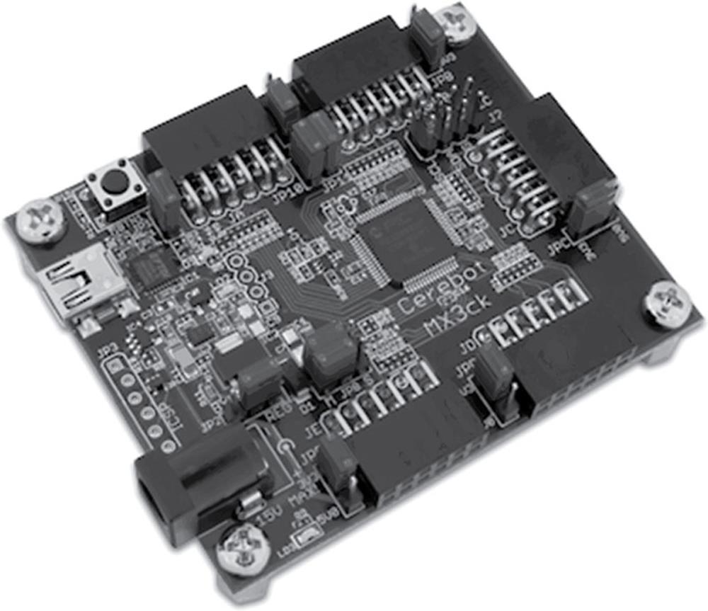
FIGURE 3.6 Cerebot MX3cK
The kit has the following features:
• PIC32MX320F128H 32-bit microcontroller
• An 80 MHz maximum operating frequency
• Forty-two I/O pins
• Twelve analogue inputs
• Programmed using MPIDE or MPLAB IDE
• Pmod headers for I/O signals
• I2C connector
• Powered via a USB port or using an external supply
Figure 3.7 shows the functional blocks of the Cerebot MX3cK development board.
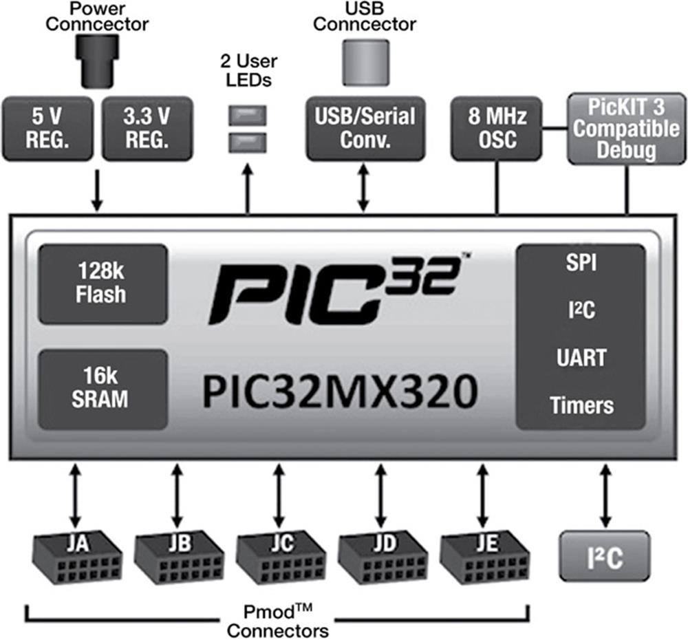
FIGURE 3.7 Cerebot MX3cK Functional Blocks
Cerebot MX4cK
The Cerebot MX4cK (see Figure 3.8) is a more advanced version of the Cerebot MX3cK with a bigger printed circuit board (PCB) area and more functionality.
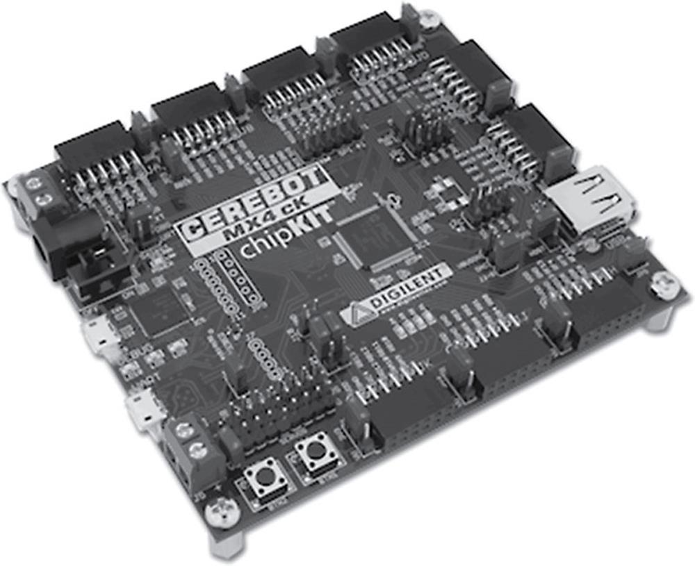
FIGURE 3.8 Cerebot MX4cK
The kit has the following features:
• PIC32MX460F512L 32-bit microcontroller
• Pmod headers for I/O ports
• 2 × I2C ports
• 1 × SPI port
• 8 × servo ports
• USB debugging/programming port (for MPLAB IDE)
• USB port for debugging/programming (for MPIDE IDE)
Figure 3.9 shows the functional blocks of the Cerebot MX4cK development board.
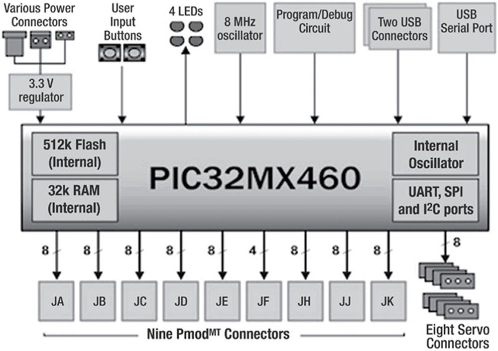
FIGURE 3.9 Cerebot MX4cK Functional Blocks
Cerebot MX7cK
The Cerebot MX7cK (see Figure 3.10) is the most advanced version of the Digilent MX series of 32-bit development boards.
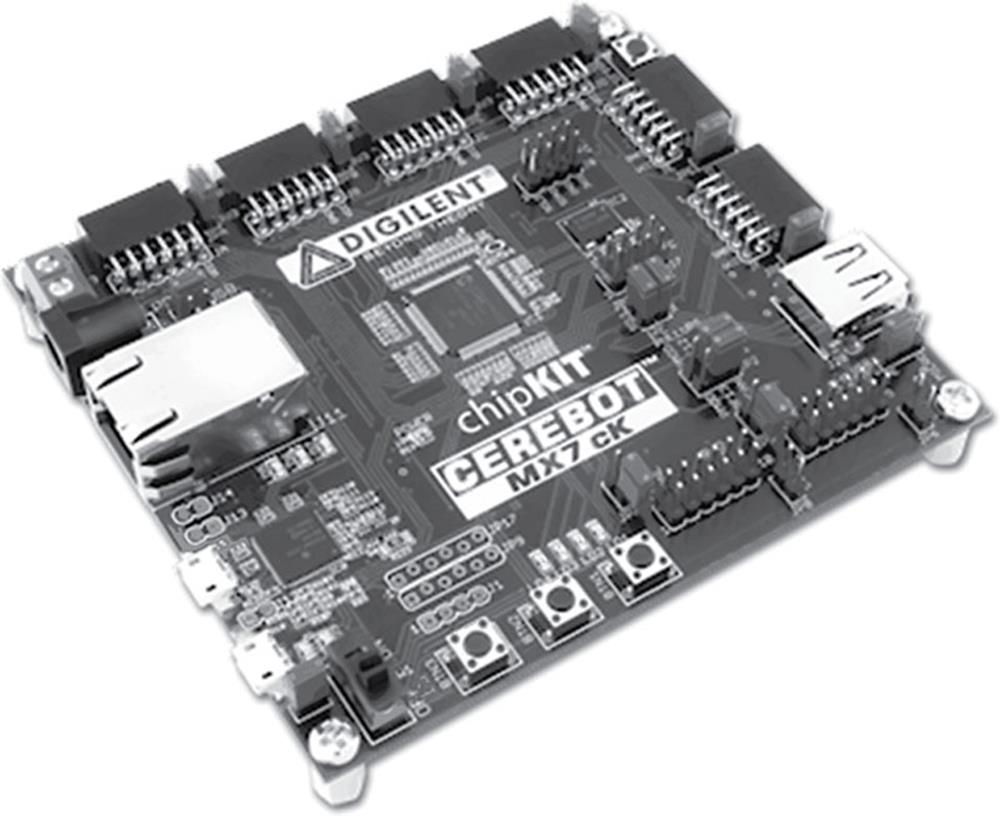
FIGURE 3.10 Cerebot MX7cK
The kit has the following features:
• PIC32MX795F512L 32-bit microcontroller
• RJ-45 Ethernet port
• 2 × I2C ports
• 1 × SPI port
• 2 × CAN ports
• 2 × SPI/UART ports
• 1 × USB UART port
• 2 × USB ports
• Pmod headers for I/O pins
Figure 3.11 shows the functional blocks of the Cerebot MX7cK development board.
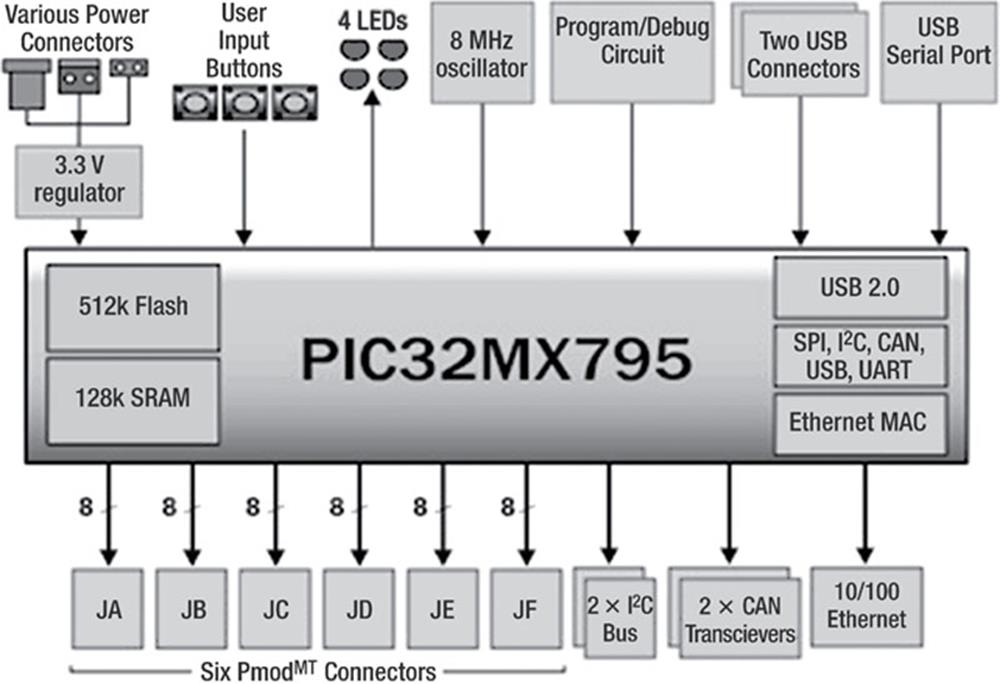
FIGURE 3.11 Cerebot MX7cK Functional Blocks
MINI-32 Board
This is a small development board (see Figure 3.12) manufactured by mikroElektronika (www.mikroe.com) that contains a PIC32MX534F064H 32-bit microcontroller. The board operates with 3.3 V power supply, and on-board regulator allows the board to be powered from a USB port.
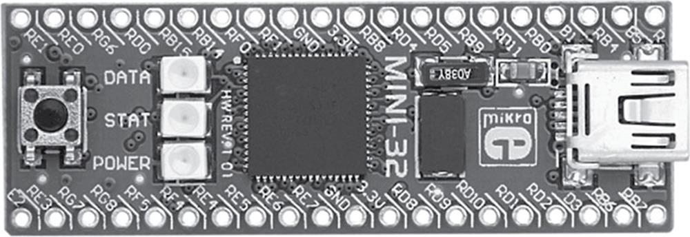
FIGURE 3.12 MINI-32 Board
The features of this board are the following:
• PIC32MX534F064H 32-bit microcontroller
• On-board crystal
• I/O pins at the edges
• Supports CAN communication
• Comes with preprogrammed USB BootLoader
• Fully supported by mikroElektronika mikroC PRO for PIC32 compiler
EasyPIC Fusion V7
The EasyPIC Fusion V7 (see Figure 3.13) combines support for three 16- and 32-bit different PIC microcontroller architectures – dsPIC33, PIC24, and PIC32 – in a single development board.
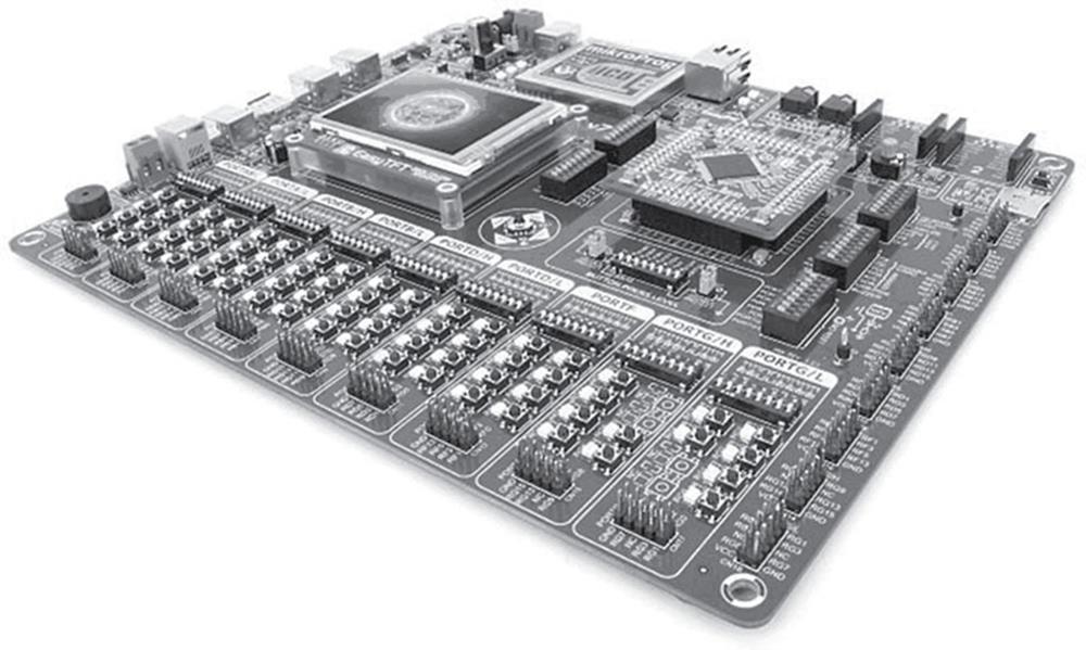
FIGURE 3.13 EasyPIC Fusion V7
The board has the following features:
• PIC32MX795F512L 32-bit microcontroller module
• On-board programmer (mikroProg)
• On-board in-circuit debugger (mikroICD)
• Sixty-eight push-button switches
• Sixty-eight LED indicators
• CAN support
• USB support
• Piezo buzzer
• LM35/DS1820 temperature sensor sockets
• RJ-45 Ethernet connector
• I2C EEPROM
• Serial flash memory
• Stereo MP3 codec
• 2 × mikroBUS sockets
• Audio in and out jack sockets
• mikroSD card slot
• TFT colour display socket
• I/O port headers
• 3.3 V power supply (can be powered from USB or external supply)
• Reset button
The EasyPIC Fusion V7 board accepts an external plug-in processor module on a small PCB. Figure 3.14 shows the processor module for the PIC32MX460F512L-type processor.
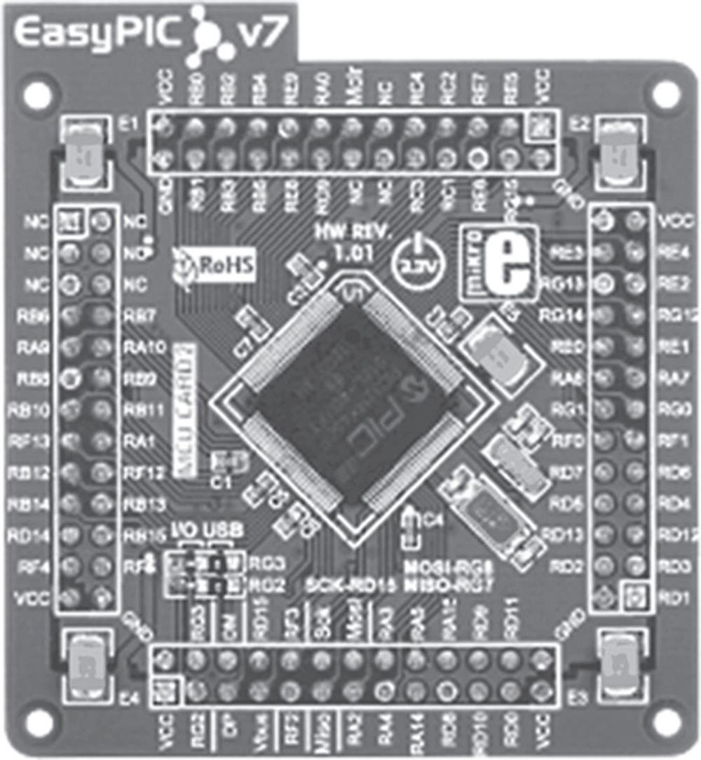
FIGURE 3.14 PIC32MX460F512L Processor Module
Mikromedia for PIC32
The mikromedia for PIC32 board (see Figure 3.15) is a small board with an integrated touchscreen TFT colour display. In addition, the board contains a stereo MP3 codec chip and a microSD card slot. The device can be powered from an external USB port or from an external battery. A preprogrammed BootLoader program enables the microcontroller chip to be programmed. The device is reset using a reset button.
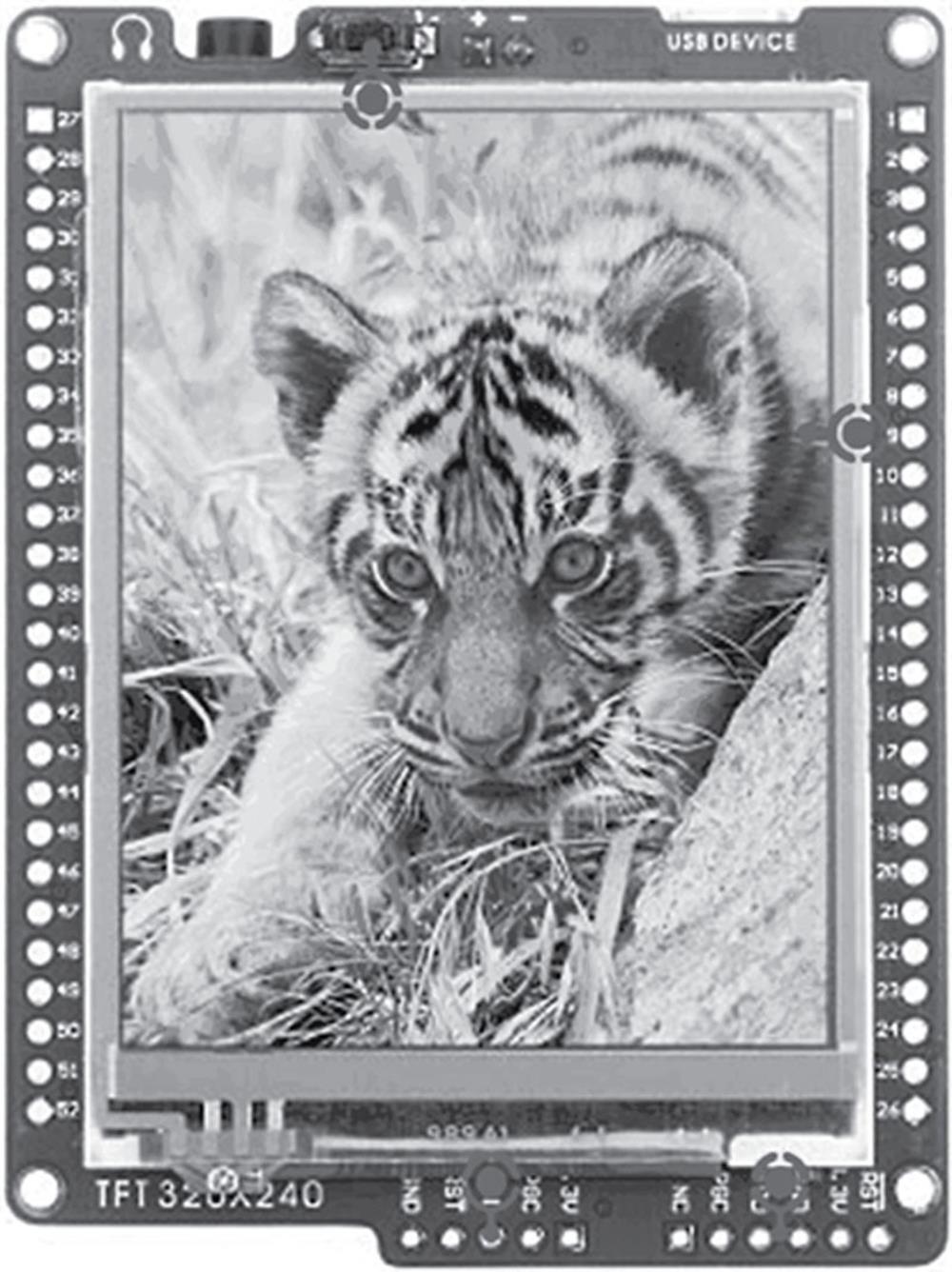
FIGURE 3.15 Mikromedia for PIC32 Board
Multimedia for PIC32MX7
This development board includes a PIC32MX795F512L 32-bit microcontroller and is used for multimedia-based applications. A large touchscreen colour TFT display is provided (see Figure 3.16) with on-board push-button switches for game applications. In addition, an Ethernet interface and a microSD card slot are available to store images or data.
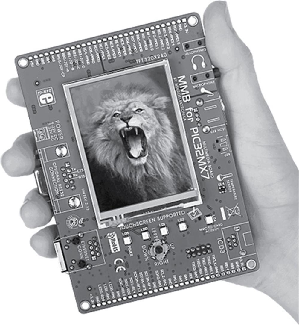
FIGURE 3.16 Multimedia for PIC32MX7 Board
Olimex PIC32 Development Board
This is a low-cost 32-bit microcontroller development board (see Figure 3.17) with a high-performance PIC32MX460F512L microcontroller (http://www.olimex.com).
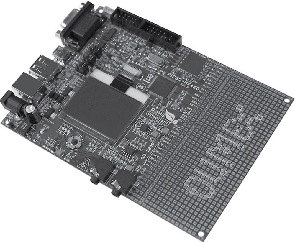
FIGURE 3.17 Olimex PIC32 Development Board
The board offers the following features:
• PIC32MX460F512L microcontroller
• Audio input and output
• USB interface
• SD card slot
• JTAG connector
• 84 × 84 pixel LCD
• On-board crystal
• Joystick
• Reset button
• 3.3 V voltage regulator
• I/O pins on connectors
• Development PCB area
PIC32-MAXI-WEB Development Board
This board (see Figure 3.18) from Olimex features a PIC32 microcontroller with an embedded 100 Mbit Ethernet module. A large 240 × 320 TFT touchscreen LCD is provided with the board for graphical applications.
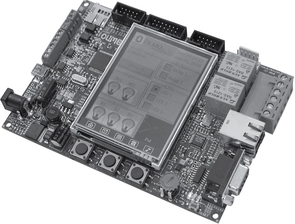
FIGURE 3.18 PIC32-MAXI-WEB Board
This board has the following features:
• PIC32MX795F512L 32-bit microcontroller
• 320 × 240 LCD
• 2 × opto-isolated digital inputs
• 2 × CAN interface
• Accelerometer sensor
• Temperature sensor
• microSD card slot
• 2 × relays
• RS232 interface
• 3 × LED indicators
• Reset button
• 3.3 V voltage regulator
LV-32MX V6
The LV-32MX V6 (see Figure 3.19) is a PIC32 development system manufactured by mikroElektronika (www.mikroe.com), and is equipped with many on-board modules, including multimedia peripherals that give great power and flexibility for system development. This development board is fully compatible with the mikroC PRO for PIC32 compiler.
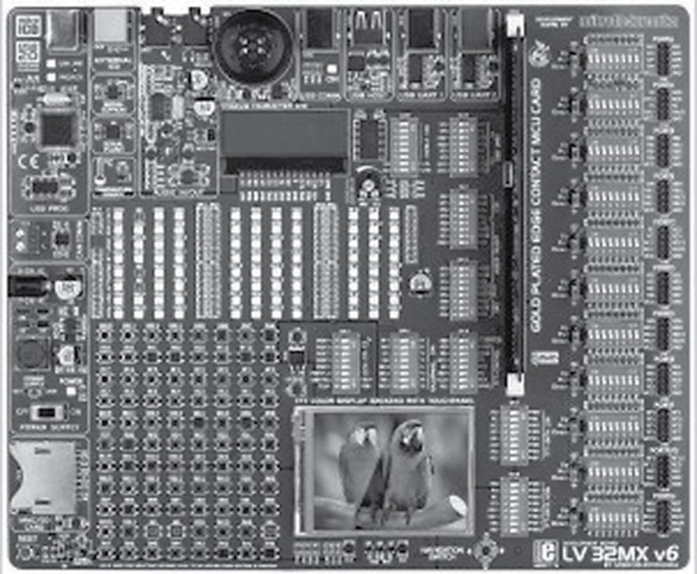
FIGURE 3.19 LV-32MX V6
The board offers the following features:
• PIC32MX460F512L
• Eighty-five push-button switches
• Eighty-five LEDs
• SD card slot
• Reset button
• Power supply regulator
• Colour TFT display with touchscreen
• CAN support
• On-board programmer and debugger
• Serial EEPROM
• Serial flash memory
• Stereo codec chip
• Chip-on-Glass (COG) LCD
• 2 × UART connectors
• DS1820 temperature sensor socket
• I/O headers
3.2.2. Device Programmers
After writing and translating the program into executable code, the resulting HEX file should be loaded to the target microcontroller program memory. Device programmers are used to load the program memory of the actual microcontroller chip. The type of device programmer to be used depends on the type of microcontroller to be programmed. For example, some device programmers can program only PIC16 series, some can program both PIC16 and PIC18 series, and some are used to program different models of microcontrollers (e.g., Intel 8051 series).
As we have seen in the previous section, some microcontroller development kits include on-board device programmers, and thus there is no need to remove the microcontroller chip and insert into the programming device. In this section, some of the popular device programmers that can be used to program PIC32 series of microcontrollers are described.
mikroProg
mikroProg (see Figure 3.20) is a small handheld programmer manufactured by mikroElektronika and supports all PIC microcontrollers from PIC10 and PIC12 to PIC16, PIC18, dsPIC, PIC24, and PIC32.
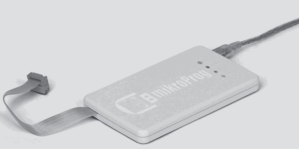
FIGURE 3.20 mikroProg Device Programmer
mikroProg programmer is supported by all the compilers of the company. The device is connected to a PC via a USB cable, and to the target development system. The microcontroller in the target system is programmed by first compiling and sending the HEX code to the programmer device.
3.2.3. In-Circuit Debuggers
An in-circuit debugger is a hardware device, connected between a PC and the target microcontroller test system, and is used to debug real-time applications faster and easier. With in-circuit debugging, a monitor program runs in the PIC microcontroller in the test circuit. The programmer can set breakpoints on the PIC, run code, single step the program, examine variables and registers on the real device, and, if required, change their values. An in-circuit debugger uses some memory and I/O pins of the target PIC microcontroller during the debugging operations. With some in-circuit debuggers, only the assembly language programs can be debugged. Some more powerful debuggers enable high-level language programs to be debugged.
In-circuit debuggers also include programming functions that enable the target microcontroller to be programmed. Some of the popular in-circuit debuggers are PICkit 3, ICD3, and Real Ice from Microchip (www.microchip.com), and mikroProg from mikroElektronika. These devices can be used with all types of PIC microcontrollers.
3.2.4. In-Circuit Emulators
The in-circuit emulator is one of the oldest and the most powerful methods of debugging a microcontroller system. In fact, it is the only tool that substitutes its own internal processor for the one in your target system. Like all in-circuit debuggers, the emulator’s most fundamental resource is target access – the ability to examine and change the contents of registers, memory, and I/O. However, since the ICE replaces the CPU, it generally does not require working CPU on the target system to provide this capability. This makes the in-circuit emulator by far the best tool for troubleshooting new or defective systems. Usually every microcontroller family has its own set of in-circuit emulator. For example, an in-circuit emulator for the PIC16 microcontrollers cannot be used for the PIC18 microcontrollers. Because of this, in order to lower the costs, emulator manufacturers provide a multiboard solution to in-circuit emulation. Usually a base board is provided that is common to most microcontrollers in the family. For example, the same base board can be used by all PIC microcontrollers. Then, probe cards are available for individual microcontrollers. When it is required to emulate a new microcontroller in the same family, it is sufficient to purchase just the probe card for the required microcontroller.
3.2.5. Breadboard
When we are building an electronic circuit, we have to connect the components as shown in Figure 3.21. This task can usually be carried out on a stripboard or a PCB by soldering the components together. The PCB approach is used for circuits that have been tested and that function as desired and also when the circuit is to be made permanent. It is not economical to make a PCB design for one or only a few applications.
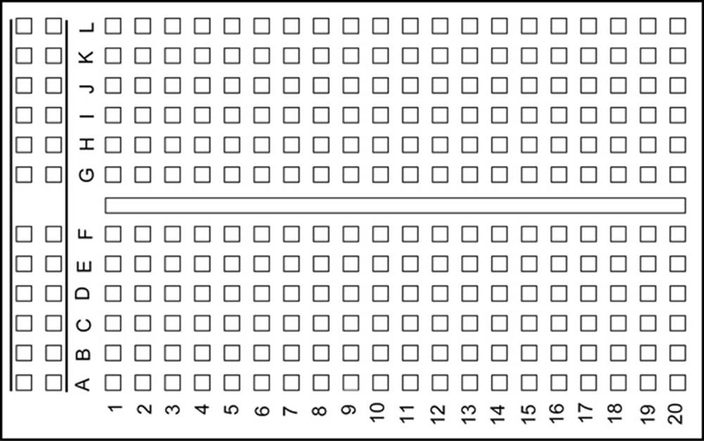
FIGURE 3.21 A Typical Breadboard Layout
During the development stage of an electronic circuit, it may not be known in advance whether or not the circuit will function correctly when assembled. A solderless breadboard is then usually used to assemble the circuit components together. A typical breadboard is shown in Figure 3.21. The board consists of rows and columns of holes that are spaced so that integrated circuits and other components can be fitted inside them. The holes have spring actions so that the component leads can be held tight inside the holes. There are various types and sizes of breadboards depending on the complexity of the circuit to be built. The boards can be stacked together to make larger boards for very complex circuits. Figure 3.22 shows the internal connection layout of the breadboard given in Figure 3.21.
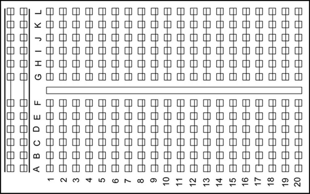
FIGURE 3.22 Internal Wiring of the Breadboard Shown in Figure 3.21
The top and bottom half parts of the breadboard are separate with no connection between them. Columns 1–20 in rows A–F are connected to each other on a column basis. Similarly, rows G–L in columns 1–20 are connected to each other on a column basis. Integrated circuits are placed such that the legs on one side are on the top half of the breadboard, and the legs on the other side of the circuit are on the bottom half of the breadboard. First two columns on the left of the board are usually reserved for the power and earth connections. Connections between the components are usually carried out by using stranded (or solid) wires plugged inside the holes to be connected.
3.3. Summary
This chapter has described the PIC microcontroller software and hardware development tools. It is shown that software tools such as text editors, assemblers, compilers, and simulators may be useful tools during microcontroller-based system development. The required useful hardware tools include development boards/kits, programming devices, in-circuit debuggers, and in-circuit emulators. The required useful software tools include assemblers, compilers, simulators, device programming software, and in-circuit debugger software.
3.4. Exercises
1. Describe the various phases of the microcontroller-based system development cycle.
2. Give a brief description of the microcontroller development tools.
3. Explain the advantages and disadvantages of assemblers and compilers.
4. Explain why a simulator can be a useful tool during the development of a microcontroller-based product.
5. Explain in detail what a device programmer is. Give an example device programmer for the PIC32 series of microcontrollers.
6. Describe briefly the differences between in-circuit debuggers and in-circuit emulators. List the advantages and disadvantages of each type of debugging tool.
All materials on the site are licensed Creative Commons Attribution-Sharealike 3.0 Unported CC BY-SA 3.0 & GNU Free Documentation License (GFDL)
If you are the copyright holder of any material contained on our site and intend to remove it, please contact our site administrator for approval.
© 2016-2026 All site design rights belong to S.Y.A.