Practical Electronics: Components and Techniques (2015)
Chapter 12. Discrete Control Interfaces
This chapter covers the basics of using a discrete signal on a single logic I/O port to sense and control things in the physical world. It also touches on topics such as buffers, logic-level translation, and current sink and sourcing considerations.
A discrete interface involves a single signal, typically binary in nature. This is probably the most common, and useful, type of interface encountered in digital electronics. It is also the simplest. It is either true or false, on or off. The microwave oven is powered on, or it isn’t. The key is in the ignition, or it isn’t. The infrared motion sensor is either active, or it isn’t. And so on, and so forth. The opposite of discrete is analog, the realm of indefinite variable values. Chapter 13 covers analog interface concepts and components.
The term discrete comes from the realm of programmable logic controllers (PLCs) used in industrial control systems, and it has an advantage over a more general term such as digital in that it specifically implies a single signal or circuit intended for use as an interface to some external device. The term digital could mean anything from a single circuit carrying one bit of information between ICs to the multiple signals found in a parallel digital bus. Of course, the term digital can also mean an interface that responds to or generates binary signals for use with external devices, but I’ve elected to use the term discrete to make the distinction clear.
So, who is this chapter for? It’s for anyone who wants to connect one thing to something else electronically with a simple on/off, true/false type of interface. It’s for someone who wants to be able to sense when a door or window is open, or to be able to sense a true/false condition and enable or disable something in response. This chapter is also for those who want to extend, improve, enhance, or alter the behavior of an existing device or circuit. Not knowing exactly how the circuits at the other end work makes the task more, well, challenging, but not impossible.
The following terms are used extensively in this chapter (You can also find them in the Glossary, but we present them here for convenience):
DIO
In electronics and embedded computers, DIO typically refers to digital or discrete input/output.
Digital
Being of a numeric nature (i.e., comprising discrete numeric values, as opposed to continuously variable analog values). May refer to a measurement or signal that has only two possible values: 1 or 0, on or off. In electronics, digital devices are those components designed specifically to work with binary values.
Discrete
Something with two or more specific values, not a continuous range of values (i.e., analog). A term commonly used with programmable logic controller devices but can refer to any binary input or output signal.
Channel
A communications circuit (either wired or wireless) with specific endpoints. Can comprise a single signal or a group of signals.
Pin
A terminal point. May refer to an actual pin on an IC or one terminal position in a connector.
Port
Usually refers to a group of digital or discrete signals but may also refer to a single channel within a group.
The Discrete Interface
A discrete interface can be just a single connection, as in a single terminal on a PCB, or a single wire. It might also be a collection of terminals of one type or another, such as those found in the header strips on a small single-board computer like an Arduino or BeagleBone. What makes it discrete is that each terminal is individually controllable, rather than operating as a group, such as with a bus or the parallel port for a printer.
Some microcontrollers have terminals labeled as DIO, which, as mentioned earlier, usually means digital I/O. Multiple companies sell interface modules with multiple DIO lines, or channels. Sometimes these are arranged into groups of 8, 16, or 32 bits, which can be controlled individually or used in parallel.
For example, consider the small PCB shown in Figure 12-1. The main star here is a CY7C68013A microcontroller; the remaining parts on the PCB are there to provide the clock signal for the processor, regulate the supply voltage, and support a USB interface.
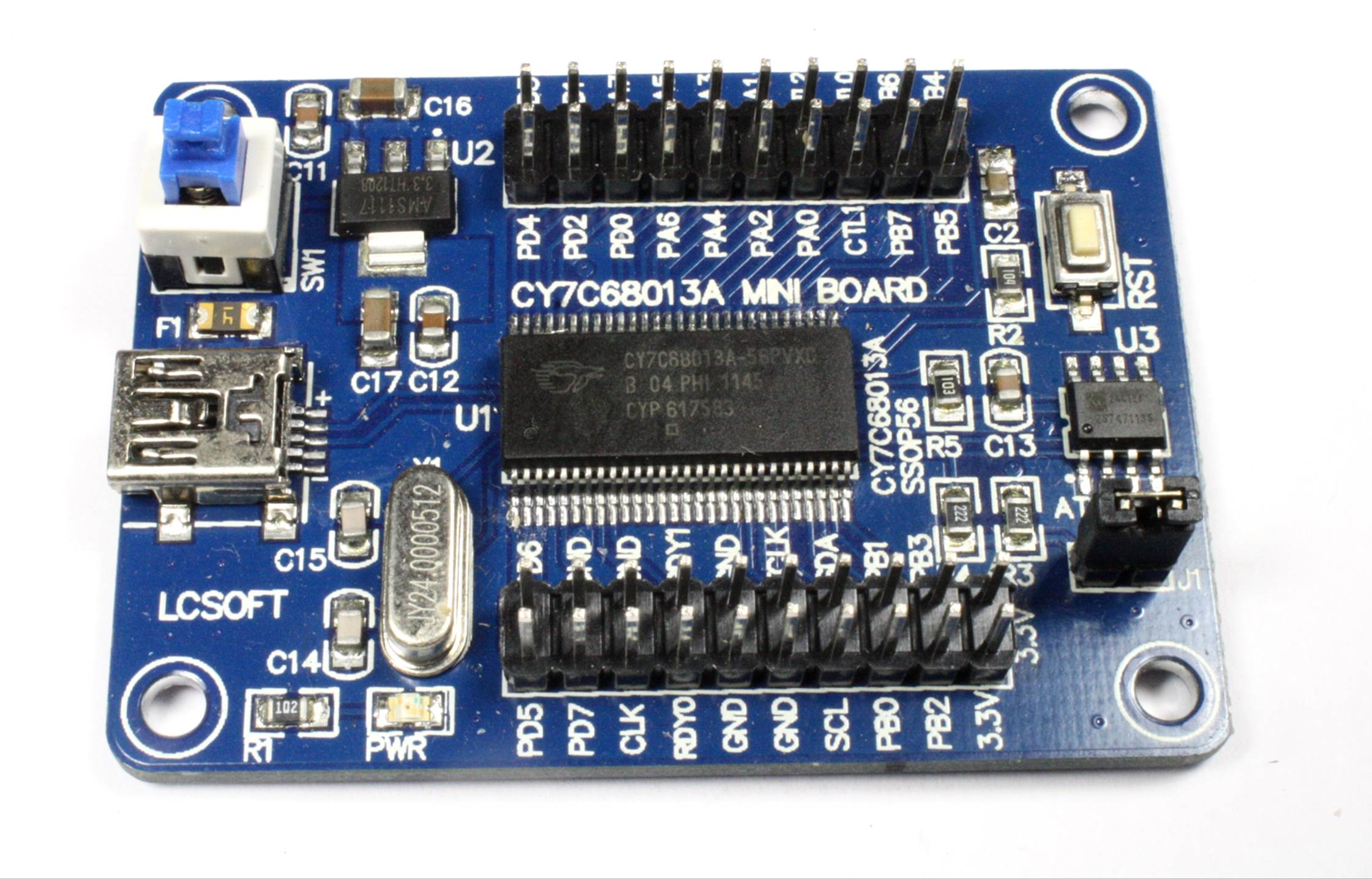
Figure 12-1. Small PCB with CY7C68013A microcontroller
The CY7C68013A is popular as a low-cost logic analyzer (see Chapter 17 for more on logic analyzers), and it is also used in numerous embedded devices. A board like this one can be purchased for around $10 on eBay.
Figure 12-2 shows a block diagram of the CY7C68013A IC, which is actually rather simple.
This particular version of the device has three DIO ports, labeled A, B, and D (other ports are not used in this version of the part, which is the 56-pin version). You can configure each pin on each port as an input, an output, or as an alternate function.
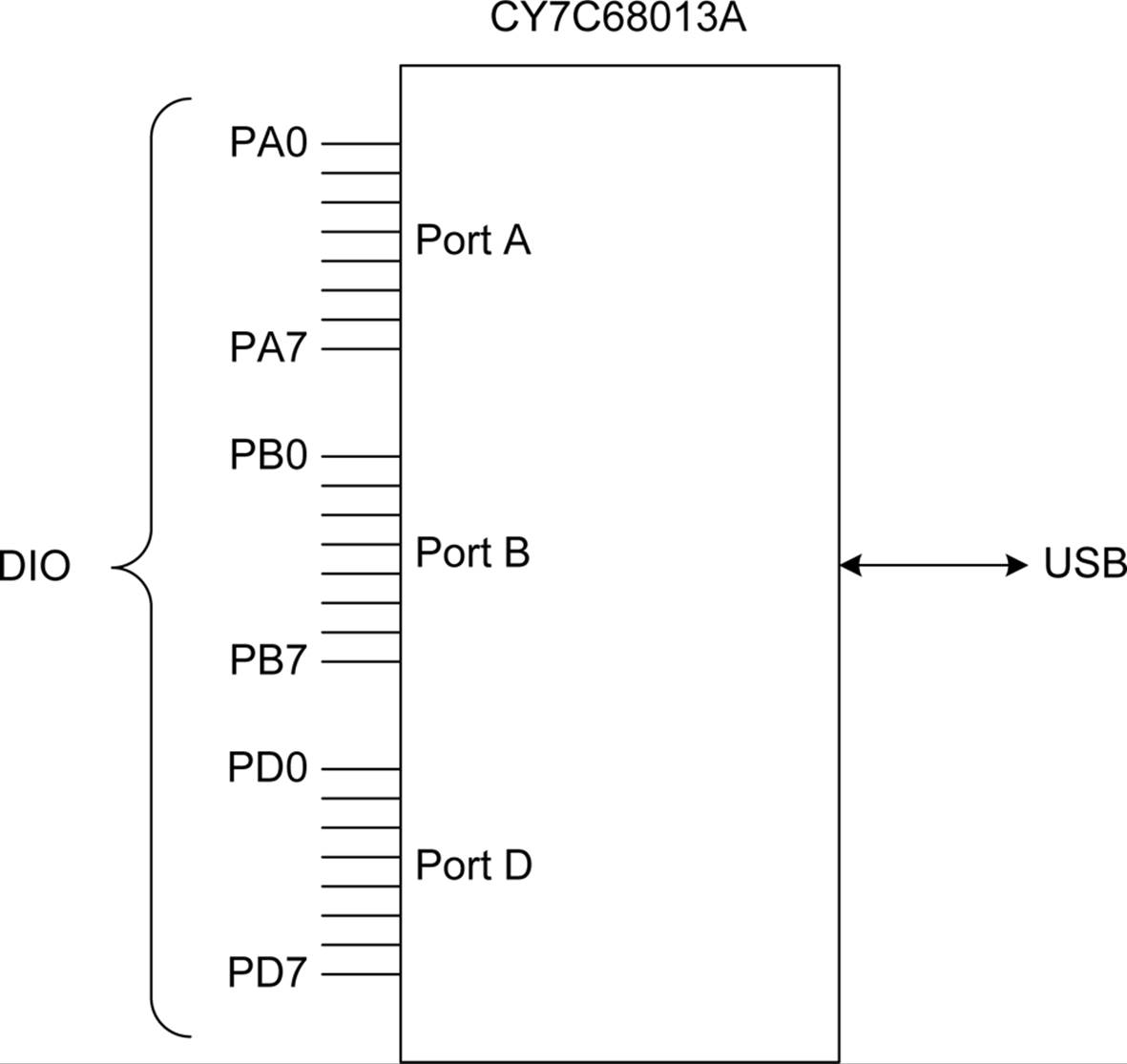
Figure 12-2. Block diagram of the CY7C68013A IC
The main thing we are concerned with here are the DIO pins on the device. As shown in Table 12-1, each DIO will accept an input voltage of up to 5.25V DC and output a minimum voltage of 2.4V DC. The CY7C68013A operates on 3.3V DC (typical). Outputs are rated at 4 mA of current, maximum.
|
Parameter |
Description |
Min |
Max |
|
VIH |
DIO input HIGH |
2 |
5.25V |
|
VIL |
DIO input LOW |
–0.5 |
0.8 |
|
VOH |
DIO output HIGH |
2.4 |
— |
|
VOL |
DIO output LOW |
— |
0.4 |
|
Table 12-1. DIO pin voltage parameters for the CY7C68013A microcontroller |
|||
With this information, we can draw a couple of immediate conclusions:
§ The DIO output functions of the CY7C68013A will most likely need low-voltage outboard components, or some type of voltage-level translation will need to be employed (see “Logic-Level Translation”).
§ The DIO pins won’t supply a lot of current, so directly driving something like a relay or an LED is not an option. A buffer or driver circuit of some type will be necessary (see “Buffering Discrete Outputs” and Chapter 10 for more on relay interfaces).
With this example as our baseline, we can move on to examine some specific functions, and look at various ways to deal with discrete interfaces.
Discrete Interface Applications
In consumer electronics, a discrete interface might be used to sense when something is open or closed (like the tray on a DVD player), or it might be used to control an LED or operate a solenoid. If you peer inside a toy like a Robosapien, you’ll notice that the various actuators are discretely controlled. The little robot moves its arms and legs only at a fixed rate, so they are either in motion or they are not. They are discrete actions.
When viewing the world in terms of discrete interfaces, it becomes immediately obvious that this type of interface is, almost literally, everywhere. Previous chapters have shown discrete interfaces, but they weren’t specifically called out as such. For example, the switches in Chapter 6, the relays in Chapter 10, and the logic in Chapter 11 are all used as discrete interface components. Here are four different catagories of applications that utilize discrete I/O functions:
User inputs
Pushbuttons on a front panel, or an old-style console game controller. The pushbuttons arranged along the sides of a display in a late-model luxury automobile or in an aircraft are discrete inputs to something, somewhere.
Limit switches
In a machine tool, various limit switches are used to detect when the machine has reached its physical limits and shut it down to prevent damage. Limit switches are common in many devices that incorporate controlled motion into their design.
Security systems
In a security system, almost all of the inputs to the local controller are discrete. Some systems have the ability to monitor temperature, but the main point is to monitor doors and windows. This is done with simple magnetic switches, such as the reed relays described in Chapter 10, hidden pushbutton switches, and sometimes snap-action type switches. If the system has infrared motion sensors, odds are that the output from those is a discrete on/off signal.
Power control
The ability to control the power to an external system, device, or mechanism is a primary application for a discrete signal. Lighting control, motor control, heater element power control, and launching a rocket are just some of the applications of discrete power control.
And there’s more. Just look around and you’ll see discrete I/O starts popping up everywhere. Sensing when a garage door is all the way down or all the way up is one example. A simple thermostat for controlling a heater or air conditioner is another example (the heater or A/C unit is either on or off, not somewhere in between). A machine on a production line that folds up a cardboard package for breakfast cereal is controlled by a set of discrete interfaces (it’s probably a type of discrete sequential controller). The popular little toy rocket launcher found on some people’s desks uses discrete actions to control the azimuth and elevation of the launcher, and when to emit a puff of air to fire the foam missile. It also incorporates discrete limit switches on the elevation and azimuth movements. There is nothing analog about the device. And the list goes on and on.
Hacking a Discrete Interface
If you are designing your own discrete interface, you have full control over the operational parameters, such as voltage, timing, pulse width, and so on. However, if you want to interface with something like a CD player or the Robosapien toy robot, you will need to figure out how its discrete interfaces work and what the electrical characteristics are.
If you have schematics for a device available, you are most of the way there. Simply examine the schematic and you should be able to figure out the basic characteristics of the circuit (see Chapter 1 and Appendix A for basic electronics theory and Appendix B for an overview of schematics). The microcontroller example shown earlier illustrates the voltage and current parameters you would probably be most concerned with.
But what if there are no schematics available, or no datasheet for a part? The first step is to observe the interface while it is active: what, exactly, does it do? What is the highest voltage when it is active? How long is it active? How much current flows through it when it is active? Once you know these things, you can then move on to create an interface that will allow you to tap into, or even override, the existing discrete interface. Chapter 17 describes the types of test instruments that can be used to discover how an interface works, including a digital multimeter (DMM) and an oscilloscope.
But what if it isn’t practical to poke at the interface while it’s active? If the mystery interface is part of a battery-operated device, a reasonable first assumption is that the voltage will not exceed what the battery (or batteries) can provide. If the device operates from a plug-in transformer, like the ones described in Chapter 5, the same reasoning applies.
If the interface is an input, the main consideration is to not apply more voltage than what the device normally uses. It should be possible to look at the input with a DMM while it is active (i.e., the gadget is doing its normal functions) and determine the high and low levels, but in any case, a relay (see “Using Relays with Inputs”) or an opto-isolator (see “Optical Isolators”) can be used to provide a safe, voltage-indifferent interface.
Consider the mystery gadget shown in Figure 12-3. It has a sensor of some sort, a small DC motor, and a solenoid. It’s shown here in schematic form because it doesn’t matter for this example what the device actually does, only how it interfaces with its various component parts.
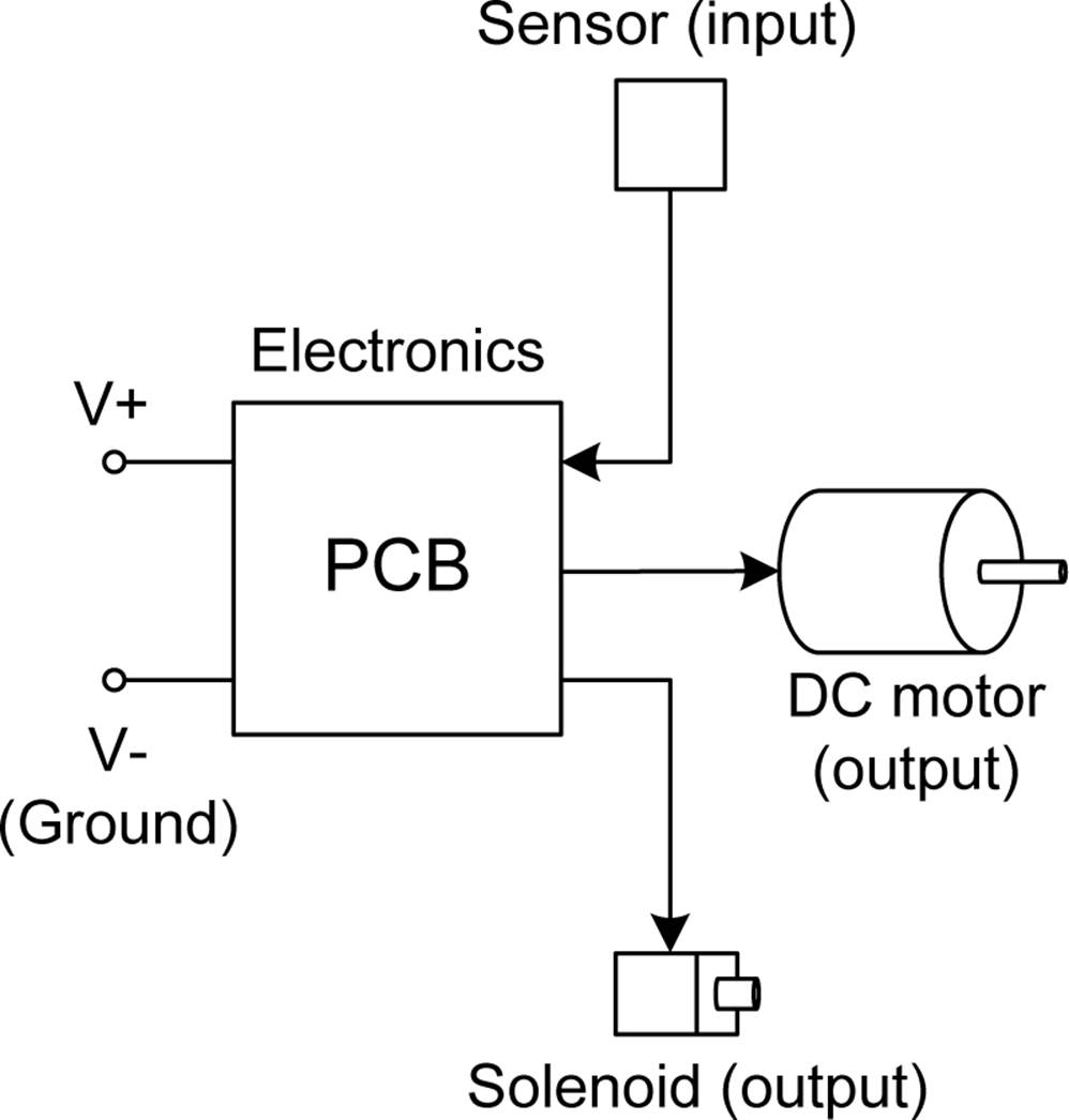
Figure 12-3. A block diagram for an example mystery device
Using Figure 12-3 as a reference, Figure 12-4 shows how to use a DMM to read the voltage on the sensor. If you suspect that it’s a temperature sensor, you should be able to blow some warm air on it and watch the voltage reading change.
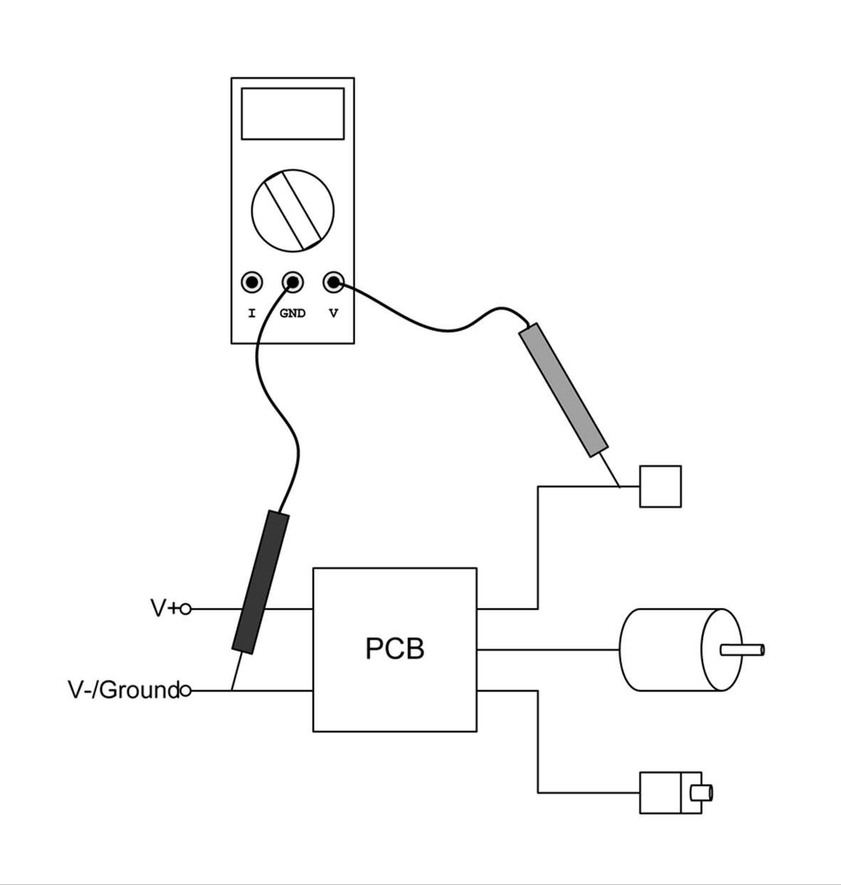
Figure 12-4. Measuring the voltage on an external sensors in the mystery device
If you notice that readings from the sensor wire don’t seem to change, and it has both an AC and a DC voltage present, you might be dealing with some type of serial digital interface. Chapter 14 describes digital interfaces, including simple serial types that are often used with outboard sensors. This would be a good time to connect an oscilloscope (see Chapter 17) and take a look at the signal on the sensor wire.
To determine how much current the motor draws, you’ll need to insert the DMM in series with the motor with it set to measure current, as shown in Figure 12-5. This isn’t hard to do, but you will need to keep in mind that the current flows through the meter in this mode, so the motor won’t work unless the meter is in the circuit. You will also need to cut the wire to the motor, strip the ends back about 1/4 inch to connect the meter, and then reconnect the wire ends when you are finished. Heatshrink tubing is perfect for insulting the reconnected wires (just remember to slide on a section of heatshrink before reconnecting and soldering the wires).
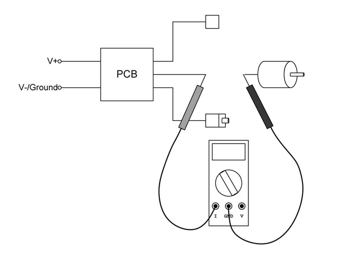
Figure 12-5. Measuring the current through a DC motor in a mystery device
By identifying the inputs and outputs of an unknown device, measuring the voltages and currents present when the device is active, and perhaps identifying some of the components, you can build up a profile. With this in hand, it will be much easier to interface your own circuit to the device with minimal guessing and hopefully avoid problems.
Discrete Inputs
A discrete input on one device is a discrete output on another. If you have full access to both ends of the interface, you can make informed decisions about current, voltage, and timing. If one end is something of an unknown, it might be best to err on the side of caution and employ some type of isolation.
A discrete input usually doesn’t require much in the way of current, just a voltage level sufficient for the circuit to sense it reliably. Depending on the impedence of the discrete input, it might be necessary to use either a pull-up or pull-down resistor to prevent build-up of stray voltage that could create erroneous input.
Using a Pull-Up or a Pull-Down Resistor
Figure 12-6 shows both pull-up and pull-down circuits. In the pull-up circuit, R1 serves to hold the discrete input (VIN) high until the external input is pulled low. In the pull-down circuit, VIN is held low by R1, and R2 serves to limit the amount of current fed into the discrete input.
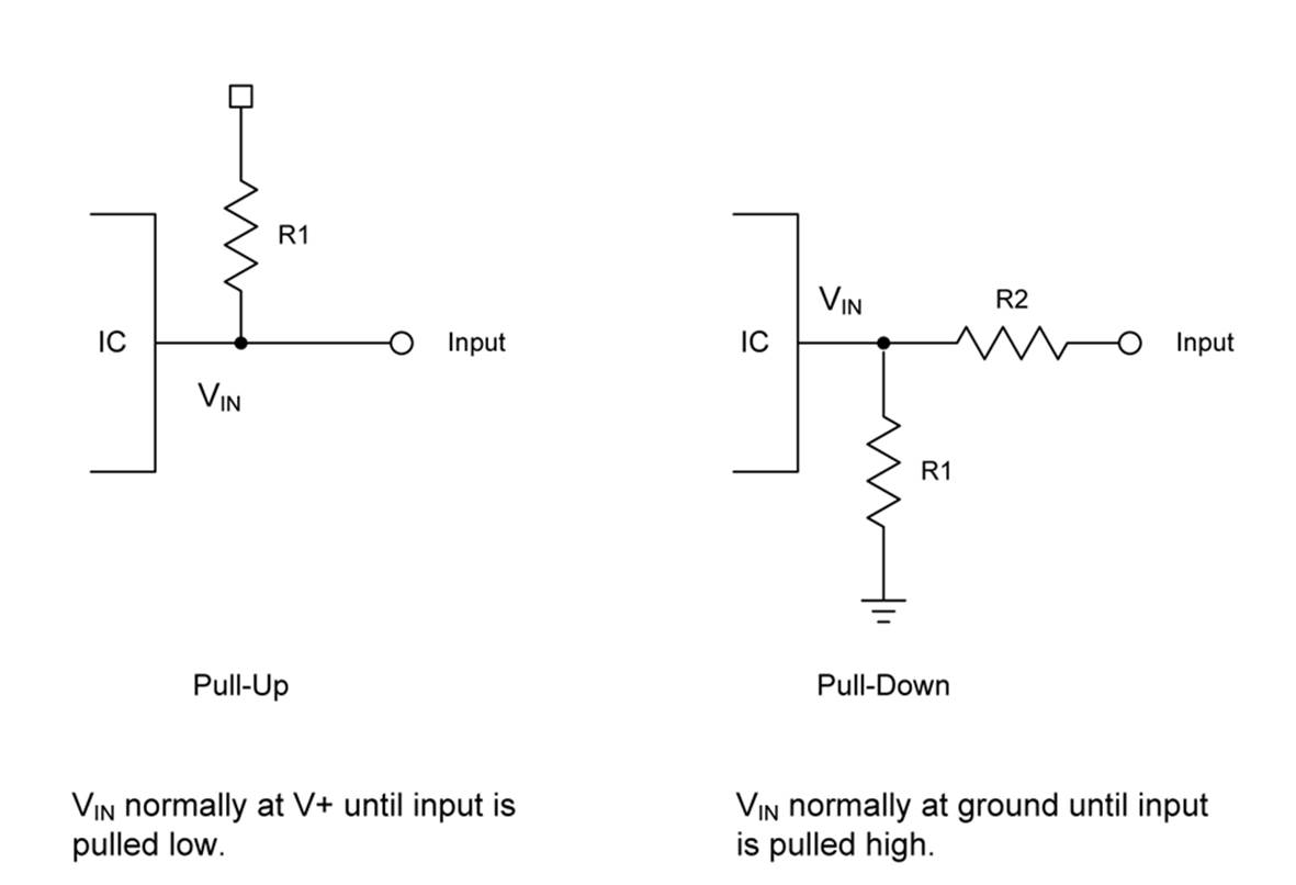
Figure 12-6. Pull-up and pull-down resistors for a discrete input
The value for R1 in the pull-up circuit might be around 22 k ohms, since all it has to do is provide a persistent voltage to the discrete input. It should be large enough so that, when the input goes to ground, the current through R1 is negligible. In the pull-down circuit, R1 can again be a high-value resistor, since it is just draining off any stray voltage to ground. R2 is a good idea to limit the amount of current fed into the discrete input, and it could be anywhere from 220 to 1,000 ohms, depending on the circuit voltage and the sensitivity of the discrete input. Also, bear in mind that in the pull-down circuit, R1 and R2 form a voltage divider and the discrete input might act as a current sink (see “Current Sinking and Sourcing”). So you won’t see VIN equal the external input voltage in many cases.
It is not a good idea to apply more voltage to a discrete input than the supply voltage it normally uses internally. This can easily damage something. So if a discrete input is part of a circuit that uses 3.3V, don’t apply more than 3.3V to the input, unless you know for a fact that it can handle a higher input voltage (many 3.3V microcontrollers can deal with 5V inputs, but not all). If you need to go from a high voltage to a lower one for the input, use a translator like the ones described later in this chapter.
Using Active Input Buffering
In some cases, it might be necessary to perform level-shifting in order to use a +5V TTL-level source with a 3.3V discrete input. Although many microcontroller devices will accept TTL-level inputs, some don’t. If you are attempting to interface to an existing device without a schematic, it might be a good idea to consider using an active input buffer.
Using Relays with Inputs
Yet another approach is to use a relay with a discrete input. Although it is the slowest form of input in terms of switching speed, it is also the safest. The contacts of a relay act as a switch connected to the discrete input, and when that is combined with the pull-up and pull-down circuits shownin Figure 12-6, you can rest assured that the discrete input will receive the same voltage at which it is designed to operate. Figure 12-7 shows how this works with the pull-down circuit.
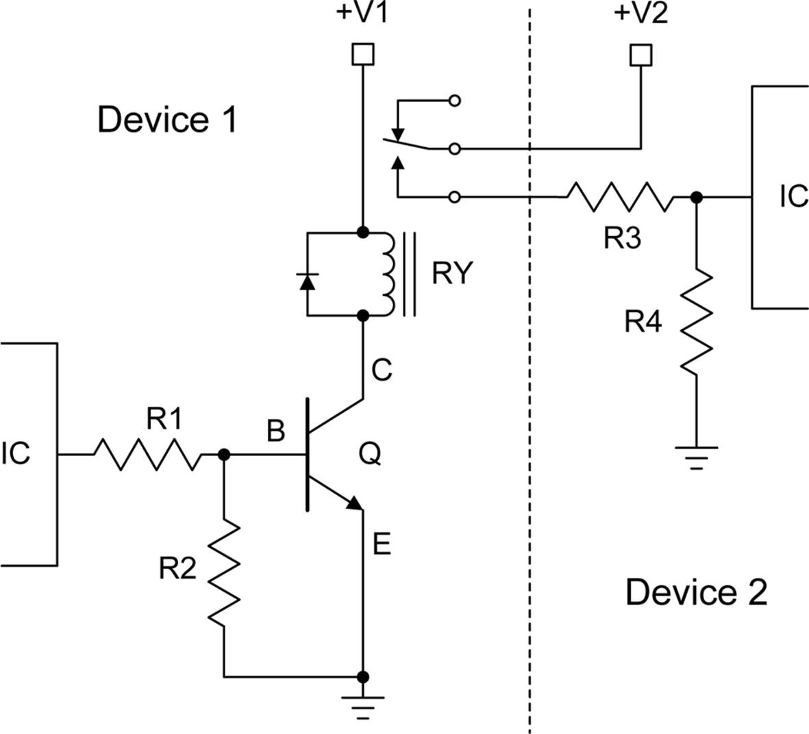
Figure 12-7. Using a relay as a safe discrete input
Once again, Figure 12-7 does not include resistor values, mainly because they will vary depending on the working voltages of the actual circuit. But, generally, R1 can be anywhere from 470 ohms to 2,200 ohms (2.2 k), and since R2 is there to ensure that the voltage across the base-emitter junction goes to zero when the input is removed, it can be something fairly large. A value between 33 k to 47 k ohms should work. R3 and R4 form a voltage divider, with R3 serving as a current limiter into the external discrete input, and R4 acting as a pull-down.
Optical Isolators
An optical isolator (also called an opto-isolator or optocoupler) is a device that uses an LED and a phototransistor of some type to couple a signal between two otherwise electrically incompatible circuits. For example, if you want to provide discrete signal feedback from a low-voltage circuit to a high-voltage circuit that doesn’t share the same ground reference, you would want to use an optical isolator. Figure 12-8 shows a generic diagram of an optical isolator.
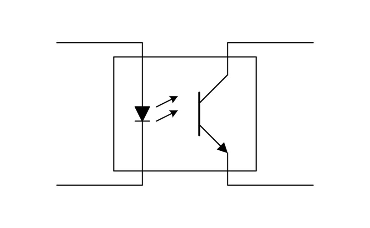
Figure 12-8. Generic optical isolator
When used with a discrete input, an opto-isolator can be used to pull down the voltage on the input when the LED is active, as shown in Figure 12-9.
Note that the circuit shown in Figure 12-9 will not invert the input. In other words, when the input goes low, the LED is active. When the LED is active, the transistor will conduct and pull the output low, as well.
Opto-isolators come in a variety of types and packages. There are simple phototransistor versions like the one shown here, as well as Darlington, AC input, and photo-triac types. Available packages range from four-pin plastic DIP to surface-mount types, and there are also tubular forms available with wire leads.
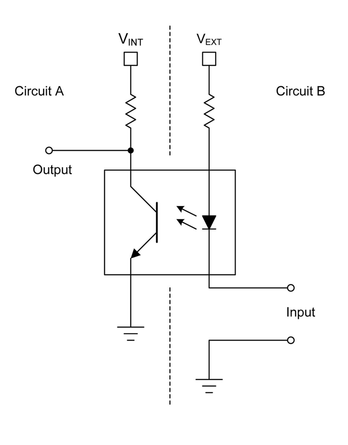
Figure 12-9. An opto-isolator used as a discrete input source
Many opto-isolator parts have numbers that begin with 4N or 6N, followed by a part number. One popular and common family of opto-isolators is the 4N25 family. These come in six-pin DIP packages as well as surface-mount types. Some types of opto-isolator and optocoupler devices are available in four-pin DIP packages. Figure 12-10 shows a 4N25 device in a somewhat unusual white DIP package.
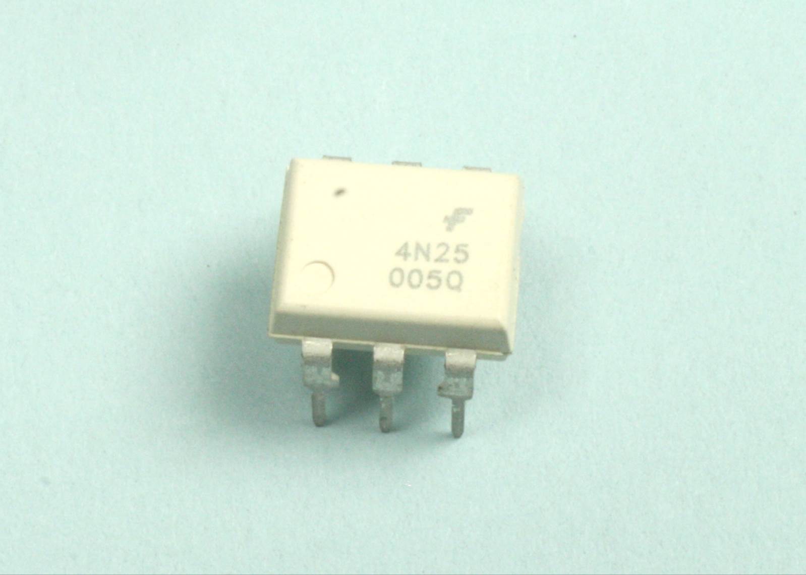
Figure 12-10. A 4N25 opto-isolator device
Internally, the 4N25 looks like Figure 12-8, but with one additional connection. Figure 12-11 shows the internal schematic of the 4N25. A unique feature here is the connection to the base terminal of the transistor. In most cases, this would be left unconnected, but it is possible to alter the response behavior of the device by connecting the base terminal to a bias voltage.
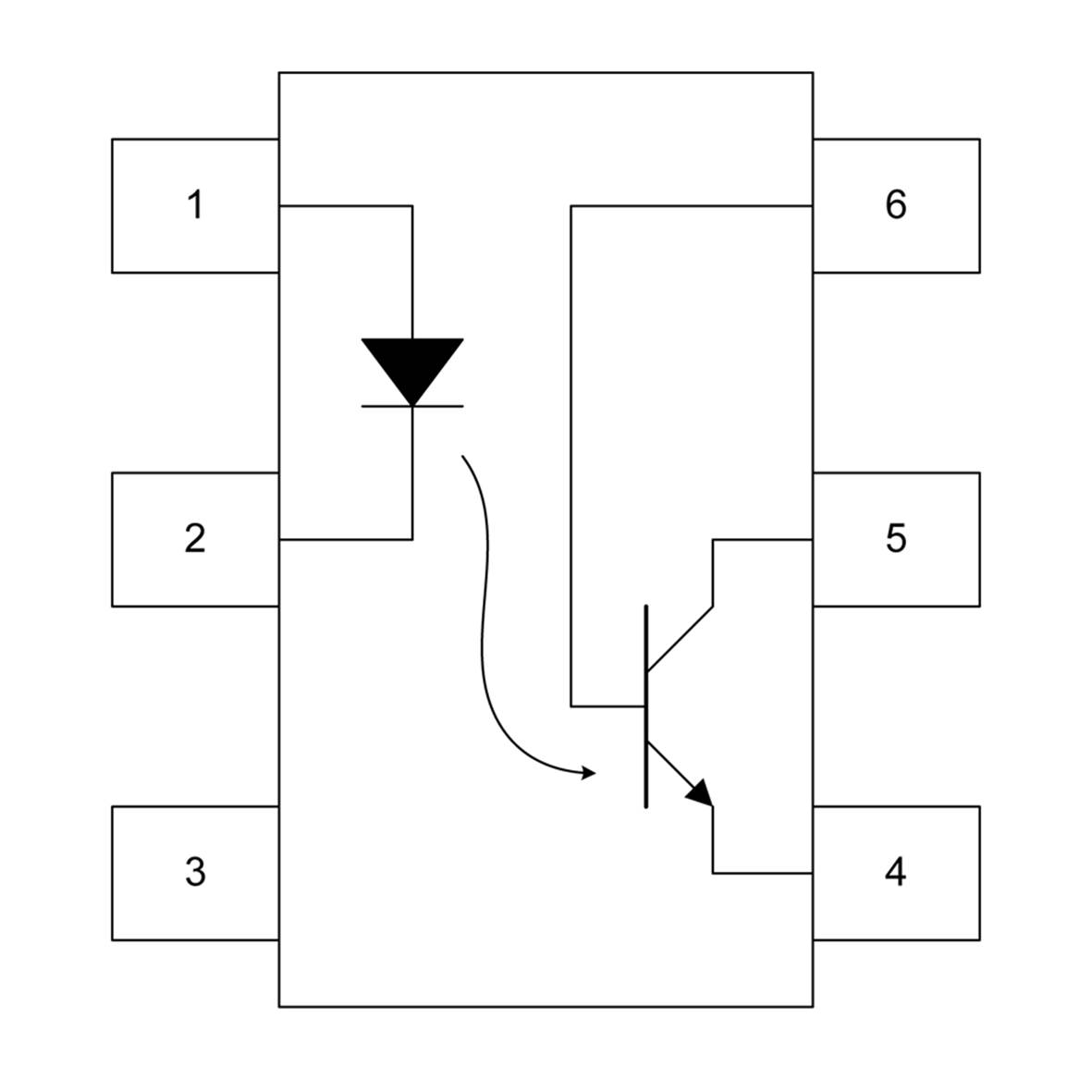
Figure 12-11. Internal diagram of a 4N25 opto-isolator
You can build your own quick-and-dirty optical isolator using just a couple of resistors—an LED and a phototransistor. Figure 12-12 shows the parts involved and the circuit diagram. The transistor is a Seimens BFH310, but just about any garden-variety type will work. The decision really becomes an issue only if you plan to push very short or high-speed signals through the isolator, and in that case, you probably shouldn’t be trying to build your own, anyway.
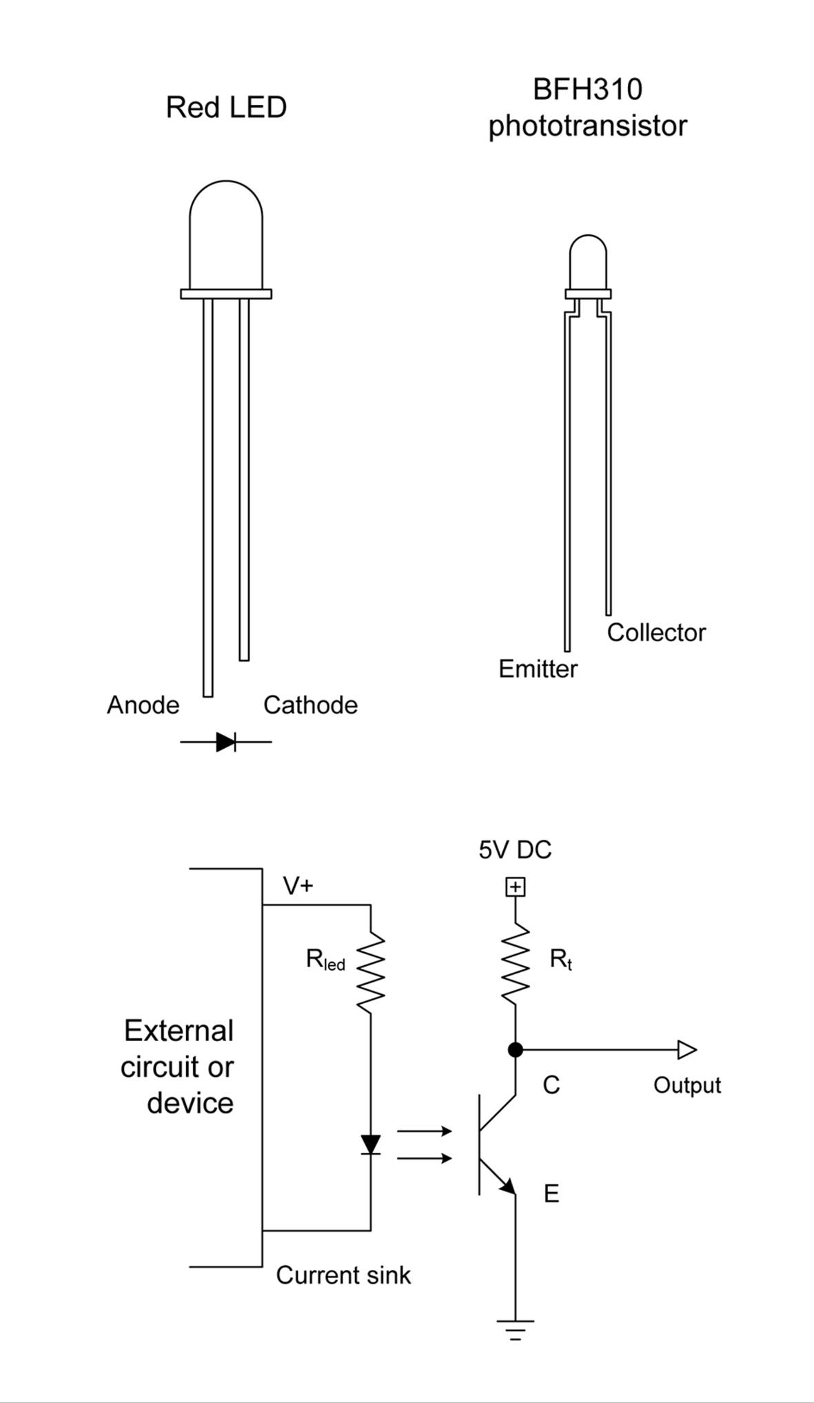
Figure 12-12. The parts needed for a home-grown opto-isolator
A light-tight package is essential for an opto-isolator. Phototransistors can sense stray light, so something needs to be placed around the LED and transistor. In Figure 12-13, that something is a short peice of heatshrink tubing, and Figure 12-14 is the real thing, ready to use.
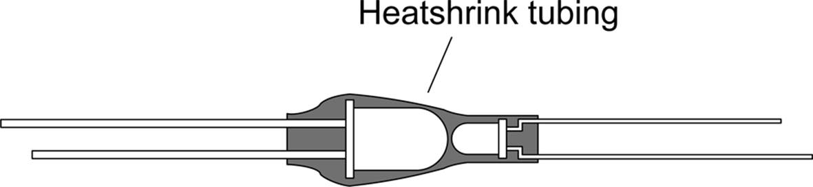
Figure 12-13. Inside a home-grown opto-isolator

Figure 12-14. The completed home-grown opto-isolator
Notice that the resistors shown in Figure 12-12 are not built into the finished isolator. Why? Because I have no idea where it might be used. If it’s a 5V to 5V situation, a 180-ohm resistor will definitely light up the LED, but it doesn’t need to be at full output to activate the phototransistor. So I’d probably go with something like a 220-ohm part, instead. The resistor used with the transistor should be capable of providing enough current for the transistor to work correctly, but no more. When the transistor sees light, it will pull the output line low (close to ground), and Rt will keep things from going up in smoke. Something on the order of 1,000 ohms will probably do the job in a 5V circuit.
Opto-isolators can be used for things other than just single-bit discrete signals. If the isolator is fast enough, it can be used to couple two circuits using a serial data channel (Chapter 14 discusses digital communications). Say, for example, you wanted to interface two microcontroller circuits, with one handling the I/O functions to a master system (perhaps using USB) and the other controlling various discrete I/O signals. Two opto-isolators are needed, one for each direction the serial data is moving between the microcontrollers. With this setup, if the control interface circuit is compromised in some way, the opto-isolators will prevent the discrete control circuit from also being damaged. The 6N26 high-speed opto-isolator, for example, can handle data rates of up to 1 Mbit/s.
Discrete Outputs
A discrete output that produces, say, 3.3V when it is active might not work directly with conventional 5V TTL logic (see Chapter 11). Your circuit might also draw more current than the original circuit was designed to supply, so it’s possible to convert something in the original device into charcoal if you aren’t careful.
Don’t forget that an opto-isolator, like the one described in “Optical Isolators”, can also be used to couple the output of an external device into your circuit. The main consideration with this approach is to choose a current-limiting resistor for the LED that will allow for sufficient current to activate the LED without exceeding the discrete output’s current limits. A driver transistor might be necessary, as described in “Simple One-Transistor Buffer”.
Current Sinking and Sourcing
A discrete interface can be either a current sink or a current source (and in some cases, both). The terms sink and source refer to how current moves into, or out of, the interface connection. Consider the diagram in Figure 12-15.
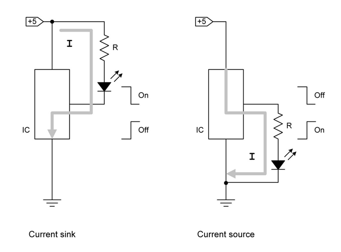
Figure 12-15. Current sink versus current source
In the case on the left, the IC is acting as a current sink. In other words, the current flow through the LED is passed into the IC and then on to ground. This is what you would expect to see with an open-collector type of device. On the right side, the IC is supplying the current necessary to activate the LED.
With a current sink, the connection into the IC (on the cathode side of the LED) will be high (at +5V in this case) until the IC closes the current path. When this occurs, the voltage on the cathode of the LED drops almost to zero. On the other hand, the voltage on the anode of the LED in the current source circuit will be zero (or very close to it) until the IC closes the path to the +5V supply.
This, then, is how you can determine if a discrete output is a sink or a source. Once you know that, you can determine the amount of current that can be safely handled by the discrete interface. Most ICs have sink and source limits published in their datasheets, but when in doubt, you should be safe if you limit the current to 10 mA.
Buffering Discrete Outputs
Whereas a digital output is typically used with other digital circuits, a discrete output implies a connection to external devices in the physical world (things like motors, solenoids, relays, LEDs, and heater elements, for example). The device that the discrete output is connected to might not use the same DC supply voltage, or it might require more current than the discrete output can safely deliver. The solution to this is some kind of buffer to serve as an intermediary between the discrete output and the external device.
Simple One-Transistor Buffer
If you need to connect to a discrete output to control something that is beyond the sink or source capacity of a part in a circuit, you will need to use a buffer. One way to do this is to use a transistor. Figure 12-16 shows how a PNP transistor can be used with a sinking discrete output to drive a high-current load like a relay. The idea here is that the transistor will not “turn on” (i.e., saturate, or become fully conducting) until its base terminal is brought close to zero volts. The discrete output from the IC does this when it is enabled by pulling down the voltage across the resistor R2 through R1. The purpose of R1 is to prevent excessive current through the base of the transistor, and it should be as small as possible. R2 should be much larger than R1, as its sole purpose is to hold transistor Q in an off state.
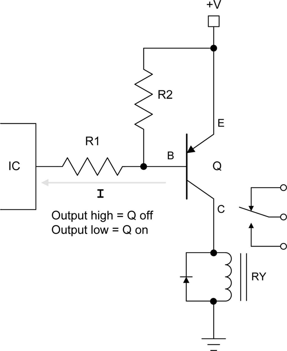
Figure 12-16. Buffer for current sink discrete output
With a current source discrete output, an NPN transistor will serve as a buffer to allow the output to drive a high current load, as shown in Figure 12-17. As with the current sink buffer shown in Figure 12-16, the purpose of R1 is to limit the base current into transistor Q, and R2 holds Q in an off state until the IC generates a voltage at the discrete output.
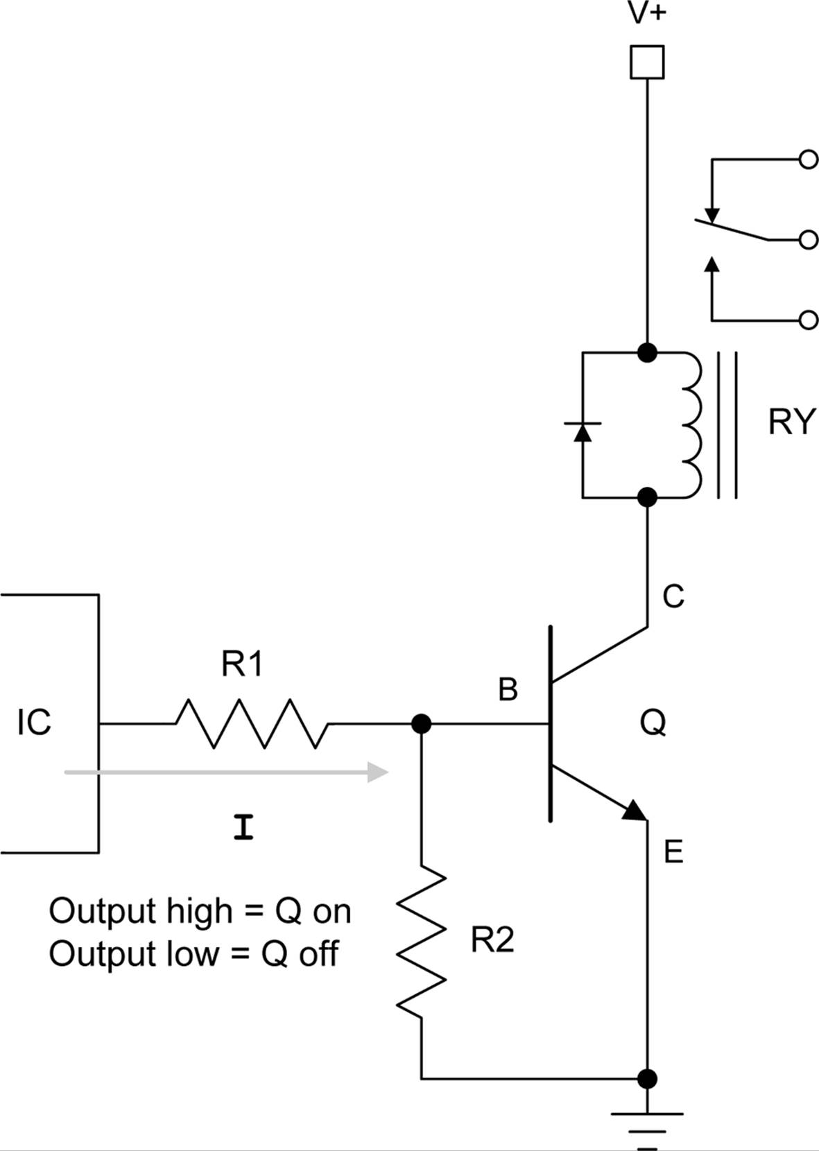
Figure 12-17. Buffer for current source discrete output
Note that the relay in Figure 12-17 can be replaced with an LED or an opto-isolator like the 4N25 discussed previously, as shown in Figure 12-18. When using an LED or an opto-isolator, don’t forget to put a resistor in series with the LED (R3) to limit the current through both it and the transistor, or smoke might result. In Figure 12-18, R3 could be something like 470 ohms if V+ is 5V.
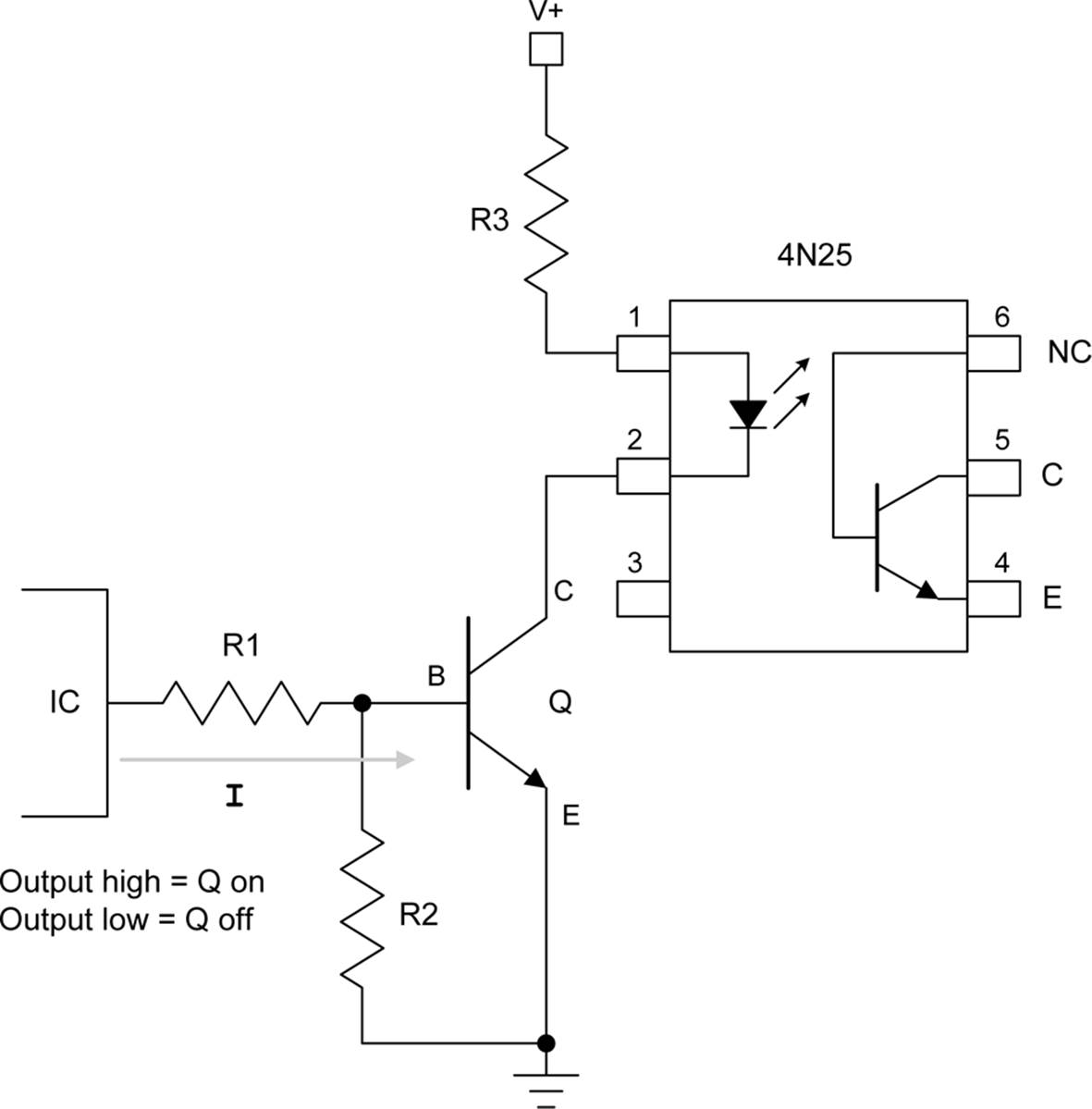
Figure 12-18. Using a 4N25 opto-isolator as a discrete output buffer
Logic-Level Translation
The widespread adoption of 3.3V logic has led to something of a dilemma when it comes to connecting things that use conventional 5V TTL logic levels to a discrete or digital input or output. While the circuits shown previously are suitable for interfacing to relays and motors, they are a bit of overkill if you just want to connect a TTL circuit to something like an Arduino (which uses 3.3V).
Fortunately, components are available that will handle the voltage translation for you. Some of them (such as the BSS138, NTB0101, or the TXB0108) will automatically sense the signal direction. Others (such as the SN74VLC245A) need external logic to change the direction of the signal, but if you need to go only one way, you’re all set.
The BSS138 FET
A field-effect transistor can be used as a bidirectional logic-level translator to connect a 3.3V discrete interface to a 5V TTL device, and one popular device for this purpose is the BSS138. The BSS138 is an N-channel MOSFET that comes in an SOT-23 surface-mount package, as shown inFigure 12-19.
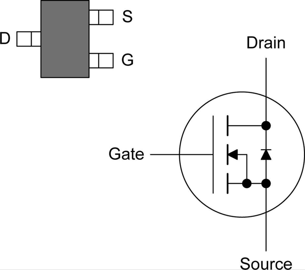
Figure 12-19. The Fairchild BSS138 FET device
AdaFruit and Sparkfun both sell a PCB with four BSS138 devices specifically for interfacing low-voltage logic to conventional TTL. In each case, these are small PCBs that contain four BSS138 devices. Connect the low-voltage side to the 3.3V logic and the high-voltage side to 5V logic, and you are good to go. The circuit itself is simple, as shown in Figure 12-20 (based on the circuit used in the Sparkfun BOB-12009 quad-level translator).
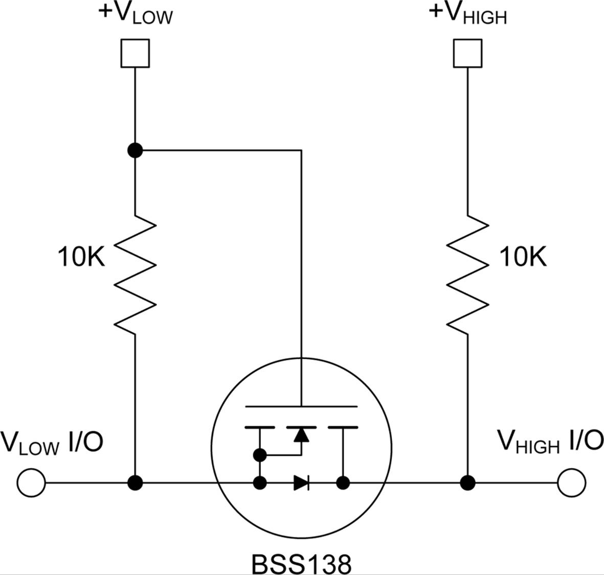
Figure 12-20. BSS138 logic-level shifter
Note that, unlike the relay circuits shown earlier, this circuit will not handle large amounts of current. The Fairchild version of the device is rated for 0.22A continuous current. It is good for interfacing logic signals, not driving heavy loads.
The TXB0108
The TXB0108 is an octal bidirectional logic-level translator with auto-direction sensing. Internally, it consists of eight identical logic cells that perform the sensing and voltage-level transation functions. Figure 12-21 shows a block diagram of the internal architecture of the device.
The TXB0108 only comes in several different surface-mount package types, from a plastic small outline form to a 2.5 mm × 3 mm ball-grid array. The plastic small outline might be a challenge, but with a decent soldering station, it can be mounted successfully. Avoid the ball-grid array package, unless you plan to use a lot of these and an automated production system to build the circuit boards.
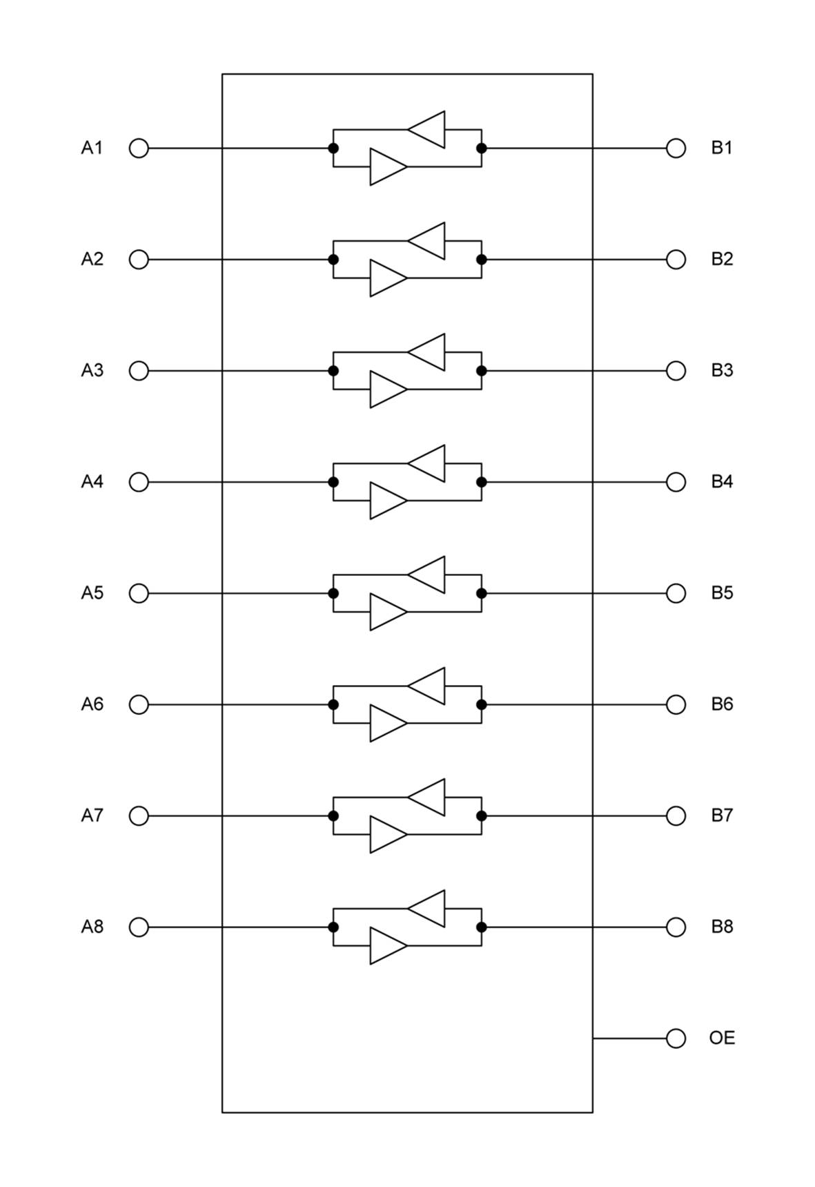
Figure 12-21. Internal block diagram of the TXB0108 octal logic-level translator
The NTB0101
The NTB0101 is a one-bit (single-channel) logic-level translator with auto-direction sensing. It comes in an SOT891 surface-mount package, which has the six connection points tucked up under the device. That might be a problem if you don’t have the equipment to deal with that type of surface-mount packaging. On the plus side, it is extremely small, with outside dimensions of only 1.05 x 1.05 mm.
Even though you might never use a part this small, it’s still interesting to take a look inside. Figure 12-22 shows what the device looks like internally.
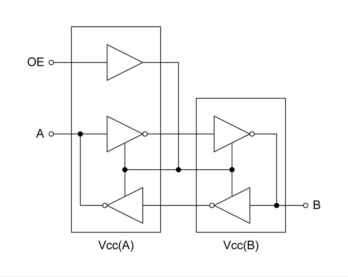
Figure 12-22. Internal schematic for a NTB0101 logic-level translator device
The OE (output enable) input controls the entire device, while the inverting buffers pass the signal from A to B (or B to A). Since two inversions in a row is the same as no inversion, the output will be the same polarity as the input.
Components
Table 12-2 lists the interface-level translation components covered in this section. There are, naturally, many more types available, but for the most part, these are fairly representative.
|
Part number |
Manufacturer |
Circuit type |
Package |
|
BSS138 |
Fairchild |
N-Channel MOSFET |
SOT-23 SMD |
|
TXB0108 |
Texas Instruments |
PMOS/NMOS logic |
SMD |
|
NTB0101 |
NXP |
Auto-sense Logic |
SMD |
|
Table 12-2. Interface-level translation components |
|||
Summary
Discrete inputs and outputs are where most circuits meet the real world, and the real world isn’t always compatible with a particular circuit. This chapter presented a variety of ways to interface with discrete inputs and outputs. We’ve looked at circuits built using transistors and relays, optical isolators, and level translation ICs.
To reduce noise and the possibility of stray voltages, use pull-up or pull-down resistors. If you need to interface a circuit with limited current sinking or sourcing capability to something that draws a lot of current, then a relay, transistor, or FET interface would be a possibility. To interface newer 3.3V logic to older 5V TTL logic, a level translator is a compact and inexpensive way to get the job done.
As with almost every other aspect of modern electronics, there are a mind-numbing number of methods and parts from which to choose. It pays to do some research and see what’s available, because it is likely that someone, somewhere, has already solved the problem and made a part or a small PCB module to do the job.
All materials on the site are licensed Creative Commons Attribution-Sharealike 3.0 Unported CC BY-SA 3.0 & GNU Free Documentation License (GFDL)
If you are the copyright holder of any material contained on our site and intend to remove it, please contact our site administrator for approval.
© 2016-2026 All site design rights belong to S.Y.A.